
From Manual to Machine-executable Model-based Systems
Engineering via Graph-based Design Languages
Benedikt Walter
1
, Dennis Kaiser
2
and Stephan Rudolph
3
1
Research & Development MB Passenger Cars, Daimler AG, Kolumbusstraße 19 + 21, 71059 Sindelfingen, Germany
2
IILS mbH, Albstraße 6, 72818 Trochtelfingen, Germany
3
University of Stuttgart, IFB, Pfaffenwaldring 31, 70569 Stuttgart, Germany
Keywords: Graph-based Design Languages, V-Model, Model-based Systems Engineering, Requirements-driven
Engineering, Executable Model, Digital Product Design.
Abstract: Today, Model-Based Systems Engineering (MBSE) is widely used in the successful design of complex
systems in various industries. It intends to provide a complete description of the design process of complex
systems in form of a V-Model or one of its various extensions thereof (extended V-Model). While already
several formal languages like Unified Modelling Language (UML) and Systems Modelling Language
(SysML) are used to formally describe the design process and behavioural aspects of the design as well,
models in UM- or SysML are still mostly assembled and connected manually. Instead, graph-based design
languages based on UML make use of the digital representation of the design process with the additional
benefit of a repeatable execution encoded in an activity diagram within a rule set. This allows for a seamless
transformation of a formerly mainly manual MBSE-approach towards a fully automated, machine-executable
MBSE approach. The article will focus on the impact of graph-based design on that transition from classical
MBSE towards machine-executable MBSE. We show this with the example of an automotive dashboard.
1 INTRODUCTION
The product development process with its various
development steps becomes more and more complex.
The need for improvements of the current product
development throughout all development steps is
therefore clearly given. Most engineering tasks are
performed in domain specific tools without interfaces
to other domains. Typical examples for frequently
used digital assistance tools are domain-specific
design and simulation tools such as CAD-kernels,
FEM- and CFD-solvers, spreadsheet calculators and
others. However, all these domain-specific models
require interfaces between each other in order to
exchange design information. Since the information
exchange between different programs often exhibits
design information losses, the interlinked design
models are often inconsistent to each other, which
causes serious information gaps in-between the
various design models throughout the development
process. One approach to resolve this issue is a
generic and abstract central model which can be
translated into each desired domain-specific model. It
serves as a single source of truth for complex design.
Graph-based design languages possess such a central
model (called design graph) in UML and are capable
to map this into many domain-specific target formats.
With this novel approach, an abstract digital twin of
the developed product can be created in UML. It is
adjusted and refined throughout all development
steps: Formal requirements engineering, digital
product design and virtual verification and validation.
A formal requirements-based engineering provides
functional and logical dependencies within the model.
From these dependencies, a finite system state
machine can be derived. This state machine is
consistent with the given system requirements and
can be tested as an executable model. It enables the
product designers to visualize the consequences and
constraints put on the model through decisions made
during requirements engineering. The dependencies
intrinsically included in formal product requirements
reduce the solution space to its true degrees of
freedom. The remaining degrees of freedom are the
actual design decisions left for product design. All
possible product variants can be considered,
evaluated and turned into design decisions. The
automation of all this allows an optimization under
Walter, B., Kaiser, D. and Rudolph, S.
From Manual to Machine-executable Model-based Systems Engineering via Graph-based Design Languages.
DOI: 10.5220/0007236702010208
In Proceedings of the 7th International Conference on Model-Driven Engineering and Software Development (MODELSWARD 2019), pages 201-208
ISBN: 978-989-758-358-2
Copyright
c
2019 by SCITEPRESS – Science and Technology Publications, Lda. All rights reserved
201
inclusion of all relevant design domains. This is
called digital product design. It is based on a central
model in one design language while optimizations are
performed in domain specific models. This derived
digital product or digital twin can be digitally verified
and validated against the given tests derived from
formal requirements. Digital verification and
validation within an executable model bridge the gaps
occurring in the existing manual development
process. It provides a solution approach towards a
consistent and machine-executable digital V-Model
via graph-based design languages. This article
presents the idea of a digital, machine-executable V-
Model with integrated and consistent development
steps and a digital twin of the product as its work item.
It will illustrate the advantages of this novel, re-
executable extension to MBSE using the example of
an automotive dashboard. The paper is structured in
the following way: First, an overview of the V-Model
with common tasks are given and put in relation to the
engineering technique of graph-based design. The
showcase in form of a (digital) automotive dashboard
is introduced and described. It is followed by three
core sections. Each section addresses one of the three
main phases of the V-Model (Specification,
Development and Testing). Each section describes
the engineering tasks for digital product development
of the particular V-Model phase. In addition, this is
applied to the showcase (automotive dashboard). The
paper closes with a discussion about limitations,
related work and an overall conclusion. The main
contribution of this paper is the presentation of an
automated, machine-executable approach that aligns
and integrates all engineering tasks occurring during
product development in one single model.
2 GRAPH-BASED DESIGN AND
DIGITAL V-MODEL
This paper combines the idea of digital product
design with the state of the art industrial product
development process in form of the V-Model. The
foundation of the digital development approach are
so-called graph-based design languages.
2.1 Graph-based Design Languages
Graph-based design languages are an abstract form of
system representation and the corresponding design
process in form of a graph. Background and
foundational approaches are mentioned in section 8.
This work focuses on an approach developed and
proposed by (Rudolph, 2006 and Rudolph et al.,
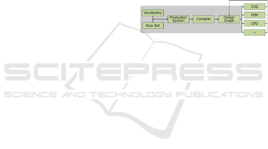
2013). Figure 1 provides an overview about this
particular approach. The total of all entities occurring
in the design is called vocabulary. In the approach all
vocabulary is represented in a class diagram, thus
each entity is represented as one class with attributes
and relationships (links, dependencies and others) to
other classes. From the class diagram, objects are
instantiated. This is controlled through a rule set. It
defines when classes instantiate objects and how
these objects are linked to each other. Vocabulary and
rule set therefore build a 'production system'. The rule
execution with object instantiation creates the so
called 'design graph'. Nodes in the graph are abstract
objects (class instantiations) and edges represent
relationships and dependencies between the objects.
Figure 1: Graph-based design process (Rudolph, 2006).
In addition, boundary conditions and underlying
equations exist, must be considered and solved.
Generating the graph and solving the equation system
is performed in one step by a design compiler. The
compiler generates the graph and the 'solution path
generator' solves the underlying equations. The
design graph is an abstract representation of the
system and is thus a general model. To work with and
consider specific domains, interfaces to particular
domains like CAD, FEM and others are required.
Through the interfaces domain specific models are
derived. In the specific domain, analysis can be
performed. The adjustments are fed back to the
general model through so called 'round trip
engineering'. This approach is the backbone of the
digital product development presented in this paper.
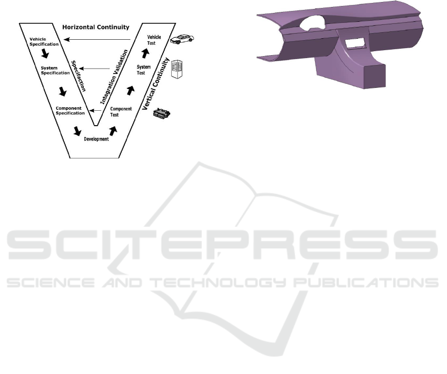
2.2 Digital V-Model
In development of complex systems, the V-model is
state of the art. It combines the three core steps of
product development (specification, design and
development and verification and validation). The
classic V-Model (figure 2) contains the 'vertical
continuity' along the ‘V’, which already existed in the
waterfall model. This means that each phase provides
work products to the next phase. In addition, the
'horizontal continuity' allows back linking from
verification and validation with the test items and test
results to the specification phase and its requirements.
MODELSWARD 2019 - 7th International Conference on Model-Driven Engineering and Software Development
202
While in theory all three steps are well integrated, in
industrial setups the steps are usually detached. A
specification phase and development phase often do
not align. Specification is seen as a needed
documentation but often not as a useful development
artefact. This is often due to the informal nature of
requirements in classic development.
Figure 2: V-Model (in automotive context).
The proposed approach in this paper digitalizes
both phases (in fact all three phases. Software-in-the-
loop (SIL) and model-in-the-loop (MIL) tests can be
performed virtually) and naturally aligns them. The
following sections show the formalization of
requirements (section 4) during specification, digital
product development (section 5) and digital
verification and validation (section 6). All work items
are formally described and provide useful input for
the next development phase. The formal and digital
gestalt allows a repetitive execution with adaptations
(adjusted parameters, boundary conditions, different
design variants). We call this re-executable V-Model.
3 SHOWCASE
In the following, a dashboard is used as an illustrative
example. The dashboard has already served as public
demonstrator in ITEA3-Project IDEALISM. It
includes engineering services of an automated finite
element analysis and an automated 3D wire harness
model generation. In the ITEA3-Project IDEALISM,
the dashboard had a predetermined class A surface
(usually defined by industrial product designers, here
simplified due to intellectual property issues) and, a
customer specific wire-harness. In terms of the
machine-executable V-Model, the development
process is following a sequential processing of the
requirements. First, the car options (provided by the
customer) are processed. Typical customer options
are add-ons such as the navigation system option, a
better sound system or a rear driving camera.
Together with the class A surface specified by the
design department, all these additional equipment or
switches lead to the final geometry of the automotive
dashboard (see figure 3).
Figure 3: Simplified dashboard geometry (ITEA3, 20018).
Since the electric system for the light system of
the car needs to be incorporated, all the control
software for the controller hardware and all electrical
cable connections between the electrical components
need to be designed. The complete automation of the
electrical 3D wire harness model generation and an
automated finite element analysis of the dashboard
cross beam has already been successfully
demonstrated in the ITEA3-Project IDEALISM.
Thus, the paper will focus on the automated,
requirements-driven generation of the software for
the outside light system. Of course, there will be some
simplifications in respect to the full light system. The
code generation is limited here, in the way that the
light system consists of simple headlights and a set of
left and right turn indicators.
4 REQUIREMENT
ENGINEERING
The first phase of product development in the V-
model is concerned with requirements engineering. In
classic approaches, documentation occurs in textual
form. While this form is needed for non-engineering
tasks like marketing, law and others, the complexity
of today's systems cannot accurately be expressed in
textual requirements. To maintain the textual form
while adjusting to formal representations, a text-to-
model (T2M) transformation seems suitable. (Walter
et al., 2017) showed such formalization from
structured textual representations to finite state
machines (FSM). This section recaptures this
approach and places it into the overall graph-based
design methodology. Subsection 4.1 introduces the
general formalization idea. Subsection 4.2 applies it
to functional requirements, which allows generating
From Manual to Machine-executable Model-based Systems Engineering via Graph-based Design Languages
203
the inner logic of a product in form of a FSM. In
addition, Subsection 4.3 shows how formalized non-
functional requirements can provide a starting point
for geometry and topology design of the product.
Functional and non-functional requirements are
shown with the previously introduced dashboard.
4.1 Formalization
Textual represented requirements are state of the art
in industrial contexts because natural language (NL)
can be created and read simple. While this is an
advantage of such unstructured textual expressions,
such representations are prone to syntax errors,
inconsistencies and are not easily processed machine-
based. An applicable solution are specification
patterns. They provide a certain degree of structure.
Specification pattern systems (SPS) by (Dwyer et al.,
1998) are one common form of language patterns.
SPS provides a syntactical structure and contains an
empirical mapping to linear temporal logic (LTL).
(Walter et al., 2017) combines this approach with a
reduction of LTL to first order logic (FOL) with the
underlying data structure. FOL can be put into
standard form like conjunctive normal form (CNF).
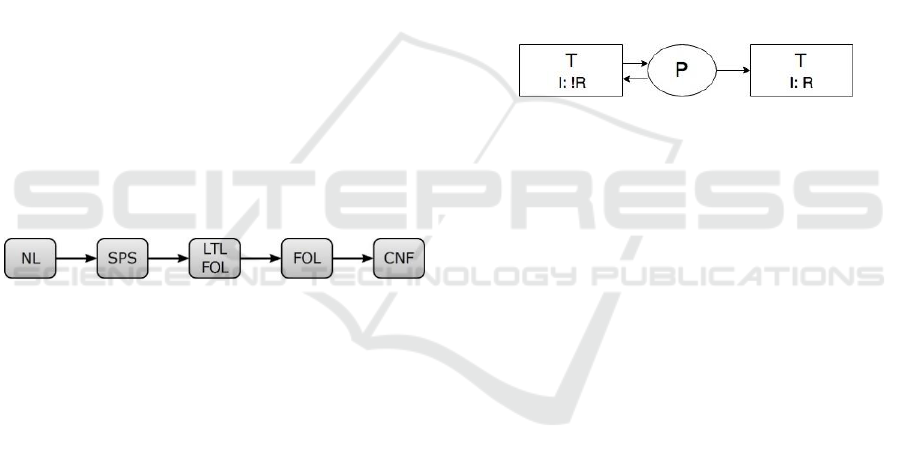
This leads to a formalization process chain from
textual description (NL) to formalized logic in form
of CNF. The general mapping is shown in figure 4.
Figure 4: Formalization process, (Walter et al., 2017).
Generally, SPS patterns are defined for functional
requirements. (Glinz, 2007) separated requirements
into functional and non-functional (NFR) with further
separation of NFR into performance, quality and
constraints. It is often not possible to represent quality
and performance requirements through SPS, yet
constrains are often simple and thus expressible in
SPS. This is useful for data represented in form of
constraints. Boundary conditions, which are often
used to express geometry in graph-based design, can
therefore be formalized. Thus, geometry can be
derived from its requirements through this approach.
4.2 Functional Requirements - FSM
Functional requirements can be formalized with the
process shown in figure 4. The example below shows
a requirement for outside light behaviour of the
automotive dashboard. Initially it is stated in natural
language (NL). An appropriate specification pattern
(SPS) is selected (see: 'SPS abstract'). The concrete
expression is created by replacing the abstract
variables with concrete system parameters.
NL: The exterior light must turn on when rotary light
switch is turned in position exterior and turned off
when turned in position off.
SPS – abstract: P is true after Q until R
SPS – concrete: ExteriorLight[Ext] is true after
RotaryLightSwitch[Ext] until RotaryLightSwitch[Off]
LTL abstract: G (Q I P U (R OR G (P)))
G - Global; I - Implies; U – Until; P = ExteriorLight[Ext];
Q = RotaryLightSwitch[Ext]; R = RotaryLightSwitch[Off]
Defined SPS to LTL mapping is used to create LTL
expression needed to derive the finite state machine
(FSM). Due to space constraints LTL and FSM are
only represented in abstract form (see: figure 5). The
given parameters can be used to generate the specific
FSM. (Walter et al., 2017) calls this 'requirement
FSM', it generates one FSM per requirement.
Figure 5: Abstract Requirement shown as FSM.
It is possible to connect multiple FSM to one
system FSM including all functional requirements.
(see Walter et al., 2017 and Kam et al., 2012). An
advantage of such an approach is, that during the
specification process, it is possible to create the
specified system FSM in real-time. This reduces
specification misconceptions as well as
inconsistencies between requirements.
4.3 Non-Functional Reqs. - Geometry
In graph-based design, geometrical forms are often
expressed through a combination of boundary
conditions and constraints. The class diagram that
contains classes for the particular geometrical
elements contains additional constraints which are
considered once the solution path generator solves the
underling equation system. By definition of (Glinz,
2007), constraints are one group of non-functional
requirements. This allows us to formalize the initially
informal process and represent functional and non-
functional requirements formally.
Req1: HorizontLengthMax[80cm] is true globally
Req2:VerticalLengthMaxUS[60cm] OR
VerticalLengthMaxEurope[55cm] is true globally
The given example provides two non-functional
requirements about the outer dimensions of the
dashboard. While HorizontalLengthMax[80cm] is
MODELSWARD 2019 - 7th International Conference on Model-Driven Engineering and Software Development
204
rather simple, VerticalLengthMax[60/55cm] depends
on the variants US and Europe. Other constraints will
specify the particular variant. The appropriate
VerticalLengthMax[*] is automatically included.
Formalizing and resolving all geometrical constraints
with the solution path generator creates a consistent
model, which can be derived to a geometry domain.
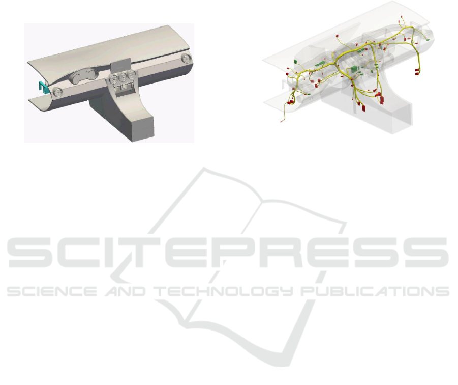
Figure 6: Dashboard geometry (ITEA3, 2018).
Furthermore, if a navigation system is included,
this navigation system needs to be provided with the
appropriate electrical connections for power and data.
Figure 6 shows the geometry of the dashboard. Since
boundary conditions are considered, the derived
model necessarily is consistent with the given
constraints. These constraints follow the normal
requirements process, which is mandatory in
industrial contexts. Requirements can be changed, the
model is updated and the geometry is derived in real-
time. If requirements are inconsistent, this becomes
apparent directly during the specification phase, not
just in later development steps. Variants can be
generated and evaluated against each other. The
following section will use the generated FSM. It
makes use of the inner logic and the created geometry
to perform particular system design tasks. We use
cable wiring as the example product design task.
5 DEVELOPMENT
In terms of the machine-executable V-Model, the
development process is steered by a sequential
processing of the requirements. First, the car
configuration is considered. This highly depends on
customization. Examples are add-ons such as the
navigation system, or a rear-driving camera. Together
with the class A surface, all additional equipment’s
lead to the final geometry of the dashboard (see figure
6). In the IDEALISM project, finite element analysis
and 3D wire harness modelling were shown as two
particular examples for digital product design with
graph-based design languages. In Figure 7, the
resulting geometry with the routed cables is shown.
This allows for all specified functionality of the
outside light control to be certainly included in the
design solution.
Figure 7: Automatic wire harness creation (ITEA3, 2018).
The geometry was created with the 3D wire
harness plug-in of the Design Cockpit 43 (IILS, 2018)
with the use of graph-based design languages. It made
use of the previously defined geometry of the
customized automotive dashboard variant.
6 VERIFICATION &
VALIDATION
This section discusses how throughout the
specification process and particularly on the right-
hand side of the V-Model, verification and validation
can be performed against the digital model. This
significantly reduces costs and time throughout
development while product quality can be
maintained. Four show cases for digital verification
and validation are addressed. This only represents a
selection of possible digital tests.
6.1 Verification – Static Analysis
The inner logic of an electric system can naturally
only be verified as soon as it explicitly exists. Classic
approaches develop the inner logic incrementally in
the development phase. This is inefficient, since the
inner logic already encodes the system requirements.
'Development' is therefore in fact only a 'pseudo-
development' in regards to inner logic which only
expresses the implicit dependencies provided in the
requirements. The shown approach allows to verify
the inner logic at the moment of the requirement
specification. It was shown in section 4, that
requirements can be converted into the system FSM
From Manual to Machine-executable Model-based Systems Engineering via Graph-based Design Languages
205

in real-time. It is therefore possible to perform static
analysis against the system FSM. This verifies the
consistency of each particular state. For example two
inconsistent parameters can exist at one state.
Req1: ExetriorLight[On] is always true when
IgnitionSwitch[On]
Req2: ExetriorLight[Off] is always true when
IgnitionSwitch[On] AND GearPos[Parking]
E.g. ExteriorLight[On] AND ExteriorLight[Off] at
one state would be inconsistent. In addition it can be
verified whether all requirements are consistent to
each other. If not, the solution space is an empty set
and no model can exist in alignment with the given
requirements. Inconsistency between requirements is
a particular valuable information and the only way to
proof, before the development phase, that no such
inconsistencies exist, is direct 'requirement-to-model'
conversion followed by verification. The given two
requirements are not consistent for at least one
particular state in the system FSM. Considering
industrial systems with more than 2000 requirements,
it is impossible to manually oversee and check for
inconsistencies. This is usually only revealed once the
system is developed. Static analysis with a model
consistent with the requirements allows for state
consistency and overall requirement consistency
before development.
6.2 Verification – Fault Tree Analysis
A system is just as robust as its weakest link. While
this is common knowledge, it is often not that easy to
proof in early design phases that a certain system
robustness is given. Fault-tree analysis is a post
process to system design and upfront guesses with
safety factors are often used. This assures that
redesigns can be avoided when fault-tree analysis
reveals insufficient system robustness after system
design is completed. Safety factors for a product
design are in fact a reduction to the product quality.
Alternative is a system redesign if robustness turns
out to be insufficient. This comes with significant
extensions in development time. Graph-based design
languages allow fault-tree analysis to be part of the
actual design process. (Riestenpatt and Rudolph,
2014) showed that it could be included in system
design by adding failure probabilities to all
components and including the architectural structure
into the analysis. Architectural structure allows to
calculate whether a component as a single point of
failure or a component with a backup system (failure
probability arises from the parallel connection) is
required. In contrast to classic design, this analysis is
part of the system design. Minimal accepted system
robustness is given and all design variants are
calculated for its system robustness. All variants with
insufficient robustness are excluded from the set of
possible correct solutions.
6.3 Validation - Physical
The dashboard cross beam needs to be functionally
qualified with the use of a finite element analysis.
Graph-based design allows for such a qualification
with an FEM-analysis by triggering an external tool
and feeding results back to the main model. Results
are shown in Figure 8. The displacements using an
artificial colour plate. Based on the finite element
analysis, a modal analysis can be computed to get an
indication about the first eigenfrequencies.
Figure 8: Finite Element Analysis (ITEA3, 2018).
6.4 Validation - Functional
The classic prove of functional correctness is
performed by testing the finished physical product
and its functionality. The digital twin contains correct
geometry and the state machine provides
functionality. An executable state machine therefore
allows for a digital functional test. In digital form. this
can be performed much earlier in the life cycle and is
therefore cost-efficient. Due to space constraints, we
cannot elaborate further on this topic.
7 LIMITATIONS
In this section, we want to address potential
limitations and address whether these challenge the
overall approach. The most relevant question is how
well does a digitally designed model mimic the reality
and the later derived physical product. This question
should be addressed per domain. Many common
domains are already well modelled digitally in
MODELSWARD 2019 - 7th International Conference on Model-Driven Engineering and Software Development
206

isolation. Geometry (here shown with the dashboard
geometry) is established and enriched with geometry
related analysis in form of FEM, CFD and others.
Another example is the functional domain, which is
already often modelled in form of state machines. It
represent the inner functionality. The overall
contribution of this paper is mostly in the
combination of these established domains through a
general model and an integrated process, rather than
improving domain specific models. What must be
seen more critical are domains that cannot be
formalized like certain non-functional requirements,
user based design decisions and management tasks.
Our stand on this is, that while no formal description
is possible, it can simple not be considered. This is
regardless of digital or classic development. Next, we
shall address the question what domains are feasible
for such an approach. The example given here is an
automotive cockpit. Based on previous work,
airplanes, satellites and ships are feasible products.
The only limitation is, that for every new domain, a
specific design language has to be created and
implemented. For the listed products and its domains,
such design languages exist. For others we see no
limitation other than effort for design and
implementation. Overall, we see few limitations in
modelling of particular domains due to informality of
these domains, limitation in regards to availability of
domain specific design languages and shortage in
trained engineers in this field. None of the limitations
represent a significant hindrance to the approach, thus
it is useful for industrial system design.
8 RELATED WORK
The overall idea presented in this paper is built on the
idea of graph-based design as proposed by (Rudolph,
2006). This includes design languages in general, as
well as product design and industrial applications in
various domains. (Prusinkiewicz and Lindenmayer,
2012) described design languages with L-systems.
(Stiny, 1980) introduces shape grammars where
building blocks are lines and shapes instead of words.
Systematic product development is described with the
V-Model. The V-Model roots in the Waterfall model.
(Böhm, 1988) provides a comprehensive discussion
about V-Model and Waterfall model. Another
prominent collection of (industrial) product design
principals is (Pahl and Beitz, 2013) yet, all phases of
product design are only described in "semi-formal"
form. In contrast, various applications and techniques
in the field of design languages applied to the
development phases are shown with formal
approaches by Rudolph: (Schmidt and Rudolph,
2016) described abstract geometry as an essential
building block for graph-based design. Various
advantages of graph-based-driven design in regards
to geometrical and functional design were shown:
(Schäfer and Rudolph, 2005, Gross and Rudolph,
2005), both on Satellite Design, (Vogel et al., 2012) -
SCR (Selective Catalytic Reduction) systems, fault-
tree analysis in (Riestenpatt and Rudolph, 2014). The
still existing gap between development and overall
product design is closed by the work of (Walter et al.
2017). The left out phases of requirements
engineering and verification and validation are
addressed. Classic influences for requirements
engineering are (Glinz, 2007, Maalej and Thurimella,
2013) and standards (ISO 29148, 2011). Solutions for
formal and thus digital processing are presented.
(Walter et al., 2017) based his work on the use of
specification patterns for requirements engineering.
Common requirement specification patterns are
Master (Sophist, 2018), EARS (Mavin and
Wilkinson, 2009) and Specification Pattern Systems
(Dwyer et al., 1998). Further, linear temporal logic
proposed by (Prior 1967 and Kamp, 1968) are used
for formal representation. Logic is processed like
shown in (Artale and Franconi, 1998). The particular
description of finite state machines used in this work
is (Kam et al., 2012). While various fields and works
are touched and addressed, it is not possible to
mention all related work in this brief overview.
9 CONCLUSION
In this work, a re-executable MBSE approach was
presented. The premise of this paper was to introduce,
discuss and apply a digital design methodology for
industrial product design. The existing approach of
graph-based design, classically focused on product
design during the development phase. It was enriched
with the approaches for requirements engineering and
verification and validation. This allows for an
integrated and fully digital product development
process along the V-Model. Formal requirements
engineering as shown by (Walter et al., 2018) is
combined with graph-based design (Rudolph, 2006)
and various formal verification and validation efforts
like (Riestenpatt and Rudolph, 2014). The resulting
product design consists of a digital model that holds
all work items created over all disciplines along the
V-Model. The digital gestalt of the created model
allows iteration of design parameters at any step of
the design process and provides the opportunity of a
real-time re-execution of the overall process with
From Manual to Machine-executable Model-based Systems Engineering via Graph-based Design Languages
207

adjusted design parameters. All generated design
variants are consistent with the given boundary
conditions. A systematic evaluation and selection
process can be performed afterwards. Classic
approaches (without a digital re-execution) create
only one or a few design variants while this approach
explores the full solution space. It reveals full variety
of possible and consistent designs. This article
showed the process with the example of an
automotive dashboard and selected engineering tasks
(requirements formalization, cable wiring and
verification and validation). We see the approach
presented as a starting point for further digital
engineering efforts across all engineering domains.
The approach can be extended incrementally to
achieve a more digital product design process with
tremendous time and cost reduction while improving
overall product quality.
ACKNOWLEDGEMENTS
We would like to thank our collaborators: Dominik
Schopper and Claudia Tonhäuser at the University of
Stuttgart, Jens Schmidt, Roland Weil, Peter Arnold,
Marius Riestenpatt, Marc Eheim and Stefan Hess at
IILS mbH and Jan Martin, Jonathan Schmidt, Hanna
Dettki and Marco Piechotta at Daimler AG.
REFERENCES
Alber, R., Rudolph, S.”43 - A Generic Approach for
Engineering Design Grammars.” AAAI Spring Symposium
Computational Synthesis, 2003.
Artale, A., Franconi, E.”A Temporal Description Logic for
Reasoning about Actions and Pans.” Journal of Artificial
Intelligence Research 9, 1998.
Böhm, B.”A Spiral Model of Software Development and
Enhancement.” Computer 21, no. 5, 1988.
Dwyer, M., Avrunin G., Corbett ,J. ”Property Specification
Patterns for Finite-State Verification.” In Proceedings
of the Second Workshop on Formal Methods in
Software Practice, ACM, 1998.
IILS mbH,”Total Engineering Automation Vision and
Realization with Graph-Based Design Languages and
the Design Cockpit 43.” http://iils.de (May, 2018).
ITEA3, IDEALISEM. https://www.idealism.eu/
technologies (May, 2018).
ISO/IEC/IEEE 29148: 2011(E): ISO/IEC/IEEE Int.
Standard, Systems & Software Engineering Life Cycle
Processes Requirements Engineering. IEEE, 2011
Glinz, M.. ”On Non-Functional Requirements.” In
Requirements Engineering Conference, 2007
Gross, J., Rudolph, S. ”Generating Simulation Models from
UML-A FireSat Example.” Symposium on Theory of
Modeling & Simulation-DEVS Integrative M&S, 2012.
Gips, J., Stiny. G.”Production Systems and Grammars: A
Uniform Characterization.” Environment and Planning
B: Planning and Design 7, no. 4, 1980.
Kamp, H.”Tense Logic and the Theory of Linear Order.”,
1968.
Villa, T., Kam, T., Brayton, R., Sangiovanni-Vincentelli, A.
”Synthesis of Finite State Machines: Logic
Optimization.” Springer Science, 2012.
Kröplin, B, Rudolph, S. ”Entwurfsgrammatiken - Ein
Paradigmenwechsel.” Der Prüfingenieur 26, 2005.
Maalej, W., Thurimella, A.”Managing Requirements
Knowledge.” Springer, 2013.
Mavin, A., Wilkinson, P., Harwood, A., Novak, M.”Easy
Approach to Requirements Syntax (EARS).” In
Requirements Engineering Conference IEEE, 2009.
Pahl, G., Beitz, W.”Engineering Design:A Systematic
Approach.” Springer Science & Business Media, 2013.
Prior, A.”Past, Present and Future.” Oxford: Clarendon
Press, 1967.
Prior, A.”Time and Modality.” John Locke Lecture, 2003.
Prusinkiewicz, P., Lindenmayer, A.”The Algorithmic
Beauty of Plants.” Springer Science, 2012.
Riestenpatt, M., Rudolph, S.”Automated Fault-Tree
Analysis of Complex Systems with Graph-Based
Design Languages.” SECESA, 2014.
Rudolph, S.”A Semantic Validation Scheme for Graph-
Based Engineering Design Grammars.” In Design
Computing and Cognition06, Springer, 2006
Rudolph, S., Beichter, J., Eheim, M., Hess, S., Motzer, M.,
Weil R.,”On Multi-Disciplinary Architectural
Synthesis and Analysis of Complex Systems with
Graph-Based Design Languages.” DGLR, 2013.
Schäfer, J., Rudolph, S.”Satellite Design by Design
Grammars.” Aerospace Science & Technology 9, 2005.
Schmidt, J., Rudolph, S.”Graph-Based Design Languages:
A Lingua Franca for Product Design Including Abstract
Geometry.” IEEE, 2016.
Sophist GmbH,”MASTeR, Schablonen für alle Fälle”
2016.
Stiny, G.”Introduction to Shape and Shape Grammars.”
Environment & planning B: planning and design, 1980.
Vogel, S., Danckert B., Rudolph, S. ”Knowledge-Based
Design of SCR Systems Using Graph-Based Design
Languages.” MTZ worldwide 73, no. 9, 2012.
Walter, B., Hammes, J., Piechotta, M., Rudolph, S.”A
Formalization Method to Process Structured Natural
Language to Logic Expressions to Detect Redundant
Specification and Test Statements.” In Requirements
Engineering Conference, IEEE, 2017.
Walter, B., Schilling M., Piechotta, M., Rudolph, S.
”Improving Test Execution Efficiency through
Clustering and Reordering of Independent Test Steps.”
In Software Testing, Verification & Validation, 2018.
Walter, B., Martin, J., Rudolph, S.”A Method to
Automatically Derive the System State Machine from
Structured Natural Language Requirements through
Requirements Formalization.” INCOSE, 2018.
MODELSWARD 2019 - 7th International Conference on Model-Driven Engineering and Software Development
208
