
Mobile Devices as Digital Sextants for Zero-Permission Geolocation
Lorenz Schwittmann, Matth
¨
aus Wander and Torben Weis
Distributed Systems Group, University of Duisburg-Essen, 47048 Duisburg, Germany
Keywords:
Geolocation, Tracking, Privacy, Ambient Light Sensor, Mobile Web Security.
Abstract:
Sensors in mobile devices can be used to infer information about a user’s context, most notably the location.
Android apps and websites shown in Firefox for Android allow software to read the ambient light sensor,
gyroscope and accelerometer without asking the user for permission. We show that these three sensors are
sufficient to determine the rough geographical location of a user by turning the mobile device into a digital
sextant. Despite low-quality sensor data, our approach is able to determine the position of the sun and thereby
the geographical area where the user is located. Our approach works even if the user holding the device does
not cooperate in being located or employs location-disguising techniques such as a VPN. We analyze in detail
the different error sources and show in which settings and situations our approach works best. The location
accuracy was at best 146 km with a medium accuracy better than 500 km. Truncating the positional sensor
readings minimizes the privacy threat, while truncation of the ambient light sensor has almost no effect.
1 INTRODUCTION
Geolocation determines the location of a user’s de-
vice in the world. Positioning or geolocating services
are a standard feature offered by smartphones and ot-
her mobile devices. They achieve a high accuracy by
combining satellite navigation (e.g., GPS, Galileo or
GLONASS), cell tower and Wi-Fi triangulation. The
location of a mobile device is synonymous to the lo-
cation of its user and therefore subject to privacy con-
cerns. Thus, operating systems like Android or iOS,
or platforms like web browsers ask for user permis-
sion before giving location access to applications.
Unfortunately, adversaries can utilize side chan-
nels to determine the user’s location without con-
sent. A prominent example is IP address geolocation,
which allows country-level or city-level geolocation
(Triukose et al., 2012). Hiding the IP address pro-
tects from this type of geolocation, for example with
a VPN, proxy server or Tor. Prior work has shown
that freely accessible inertial sensors provide enough
information to infer the trajectory of moving mobile
devices such as acceleration of metro lines (Hua et al.,
2017) or cars in city streets (Han et al., 2012). Even
the phone’s power meter can be used to infer the loca-
tion based on cellular radio power consumption (Mi-
chalevsky et al., 2015). This enables the geolocation
of the user even when hiding the IP address with a
VPN. These approaches have in common that they
require a systematic charting of a given area subject
to specific features before geolocation becomes pos-
sible.
In this paper, we propose a zero-permission geo-
location method based on mobile sensors, which does
not require prior charting nor user permission. We de-
termine the altitude of the unobstructed sun by crea-
ting a digital sextant based on the ambient light sensor
(ALS) and accelerometer. Combined with a compass,
this allows for geolocation without prior training or
cartography anywhere on Earth where the sun is visi-
ble. However, magnetometers in smartphones used as
compasses are too inaccurate for this purpose, espe-
cially because we cannot expect the user to calibrate
them when they are unaware of being geolocated. Our
method compensates for magnetometer deficiencies
by inferring the sun’s movement with time-delayed
measurements, from which we can derive the user’s
location on Earth.
The sensors used by our method are accessible by
Android apps or even websites on Firefox for Android
without requesting user permission. The major chal-
lenge are inaccurate sensor readings by uncalibrated
sensors on consumer devices. Yet, our web-based
implementation achieves an accuracy of better than
500 km in 50% of our measurements. This shows that
malicious websites can perform a country-level geo-
location even when the user employs a VPN to hide
their location.
Schwittmann, L., Wander, M. and Weis, T.
Mobile Devices as Digital Sextants for Zero-Permission Geolocation.
DOI: 10.5220/0007254000550066
In Proceedings of the 5th International Conference on Information Systems Security and Privacy (ICISSP 2019), pages 55-66
ISBN: 978-989-758-359-9
Copyright
c
2019 by SCITEPRESS – Science and Technology Publications, Lda. All rights reserved
55

The contributions of this paper include:
1. A novel approach to locate mobile devices wit-
hout any infrastructure support.
2. A systematic evaluation of its accuracy, depen-
ding on latitude and sensor error.
3. An analysis of countermeasures based on reduced
sensor resolution.
The paper is organized as follows: Section 2 mo-
tivates an attack use case. Section 3 provides astrono-
mical background that the attack relies on. Section 4
describes assumptions about the threat model and
Section 5 the geolocation method. Section 6 descri-
bes the implementation and how to handle practical
interferences. Section 7 analyzes the practical appli-
cability, while Section 8 evaluates the location accu-
racy and causes of measurement errors systematically.
Section 9 discusses countermeasures and their effecti-
veness. Section 10 compares our work with related
approaches.
2 USE CASE
Our digital sextant achieves an accuracy suitable for
country-level geolocation. Although this is a coarse
result, it can be used as part of a multi-level appro-
ach to bootstrap a more accurate geolocation method.
There is a number of approaches for location tracking,
which require either the starting point or at least the
approximate area of where the user resides (Li et al.,
2018; ?; ?; ?; ?; Han et al., 2012). Based on an ap-
proximate position, they allow to infer vehicular mo-
vement on a street map or similar approaches. Wit-
hout any prior areal indication at all, there are too
many potential matches and the resources required to
process global map data renders the geolocation at-
tempt infeasible. Our method thus yields the approx-
imate area of the user, which can be then narrowed
down with a computationally-expensive method to a
specific location.
3 BACKGROUND
Our method is based on knowledge about planetary
movements and celestial navigation combined with
sensors available in smartphones.
3.1 Celestial Navigation
Celestial navigation relies on knowledge about per-
ceived positions of celestial bodies depending on ob-
N
Object
Altitude
Observer
Local Horizon
Azimuth
Figure 1: The horizontal coordinate system.
servation time and place on Earth. To describe ce-
lestial positions from a local observer’s perspective,
astronomers use the horizontal coordinate system (Fi-
gure 1). In it, every celestial object can be defined
using two angles: altitude describes elevation from
the observer’s local horizon and azimuth the cloc-
kwise angle between north and that point on the hori-
zon below the celestial body.
Combined with a precise location information of
the observer (latitude/longitude) and time of the ob-
servation, this uniquely defines a celestial position
and allows for identification of that celestial body. In
the opposite case, if horizontal coordinates, time and
celestial body are given, the observer’s location is uni-
quely defined, which we utilize in our method.
3.2 Planetary Movements
While the general model of Earth orbiting the sun
is well-known, various factors have to be taken into
consideration to precisely predict its celestial posi-
tion. Among these are ecliptic (tilt between rotatio-
nal axis and orbital axis), exact orbital period (leap
years/seconds), gravitational influences, day of year
and time of day. Even then, there is no universal for-
mula to describe celestial bodies precisely. Instead as-
tronomers rely on fundamental ephemeris (i.e., tables
of positions of celestial objects and their movements)
which can be used to predict future positions. These
calculations can be performed by broadly available
astronomic programming libraries such as PyAstro-
nomy (Czesla, 2013) with high accuracy.
3.3 Smartphone Sensors
Due to its brightness the sun is especially suited for
detection using an ambient light sensor (ALS). Usu-
ally, ALS are mounted on the mobile device’s front
near the camera and prefaced by a lens to sample am-
bient light from a wide angle. Silicon photodiodes
used in ALS are sensitive to a broad spectrum of light.
To approximate human perception of illuminance and
restrict that sensor sensitivity to visible light, filtering
techniques are used to ultimately yield illuminance in
ICISSP 2019 - 5th International Conference on Information Systems Security and Privacy
56

g
x
y
z
Figure 2: The mobile device records ambient light and po-
sitional sensors.
the photometry unit Lux. Nearly every smartphone
and tablet is equipped with an ALS to adjust screen
brightness, allowing for a sensor-based trade-off bet-
ween screen readability and energy consumption. Be-
sides its user interface usage, ALS readings are also
exposed to applications on Android and in the Web
API without any dedicated permission requirements.
Both APIs yield illuminance as IEEE 754 floating
points.
4 THREAT MODEL
As illustrated in Figure 2, a user holds their smartp-
hone or another smart device while being exposed to
direct sunlight. The user takes reasonable measures
to hide their location such as using a VPN and the-
reby rendering IP address-based geolocation useless.
Unconscious movements by the user cause the smart
device to be facing in various directions.
An attacker aims to geolocate the user without
their consent. The attacker can execute code without
special permissions on the user’s device, in particu-
lar without access to the geolocation API. The mali-
cious code reads the ambient light sensor, accelero-
meter and magnetometer of the user’s device. This
assumption is met by installing a seemingly harmless
app or simply visiting an HTML5 website, since the
sensors of interest to our method are exposed via Web
APIs (Tibbett et al., 2016; Kostiainen et al., 2017).
We furthermore assume the attacker runs another
measurement on the user’s device after one to six
hours and observes a different position of the sun.
This could be achieved by running the app in back-
ground or because the user visits the website a second
time.
5 METHOD
Our method to locate a mobile device consists of
1. measuring directional ambient light at two points
in time, 2. processing these measurements to find out
the sun’s altitude and azimuth, 3. calculating location
candidates and 4. finally aggregating them to a posi-
tion. We will discuss each step in detail in the follo-
wing sections.
5.1 Measurements
We start by continuously reading accelerometer, mag-
netometer and ambient light sensors with correspon-
ding time stamps. Since Android apps or websites do
not require additional permissions for this, this data
collection can be conducted without the user’s per-
mission or even awareness.
Since our approach does not control the user’s mo-
vement, we merely assume the ambient light sensor
eventually points towards the sun. We refer to this set
of collected sensor readings as one measurement. To
overcome inaccurate magnetometer values, we use at
least two measurements from different points in time,
which will be merged together in Section 5.3.
5.2 Preprocessing
Given a measurement, we want to locate the sun and
calculate its altitude and azimuth.
For this, all sensor readings are transformed to a
horizontal coordinate system. The accelerometer pre-
sents its values as a three dimensional vector (x, y, z)
where z represents the front/back forces acting on
the device. Assuming gravitational force is the main
component, we can use the normal vector of the xy-
plane to calculate the device’s facing direction, which
gives us the altitude in the horizontal coordinate sy-
stem (cf. Figure 1). When interpreted as a compass,
magnetometer readings can be used to determine the
azimuth. As we cannot expect a calibrated mag-
netometer, the resulting azimuth is shifted with an
unknown offset error. We combine these positional
sensors with ALS readings to generate a directed lig-
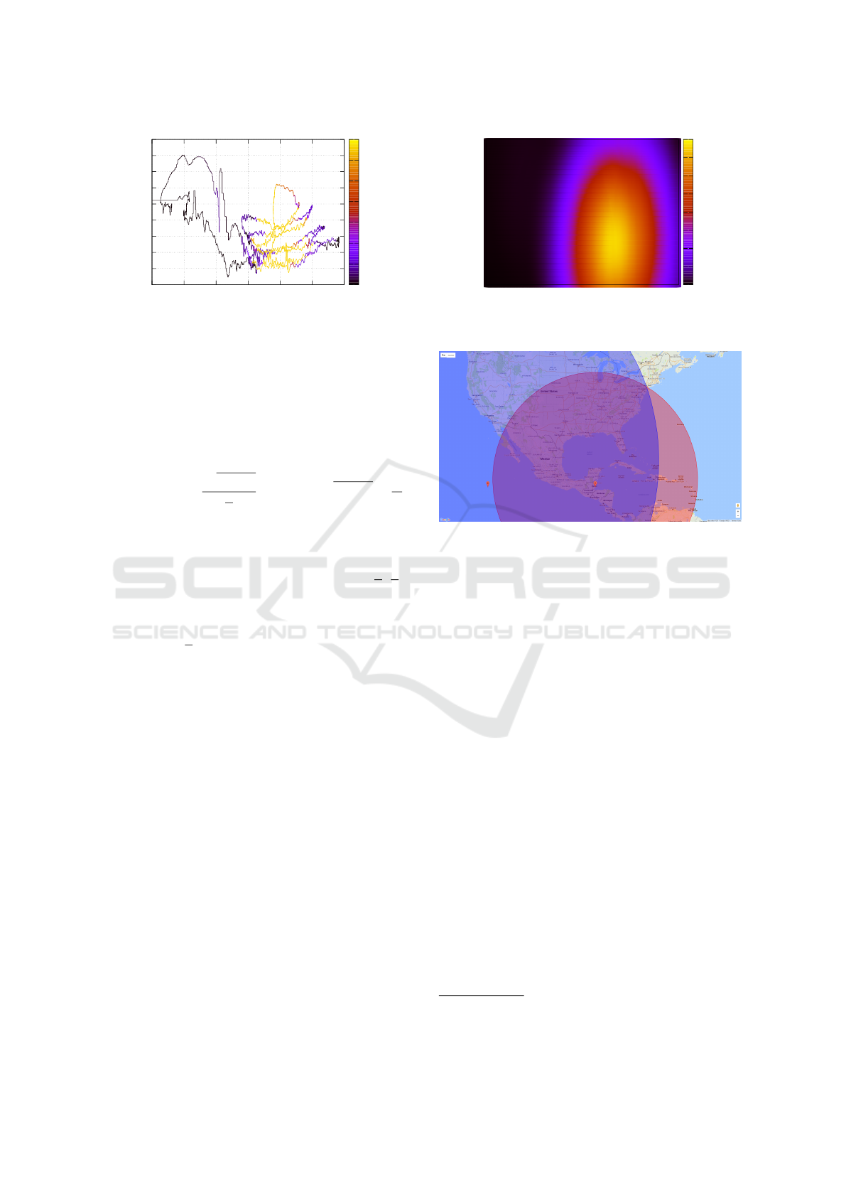
hting map. An example of such a transformed measu-
rement is shown in Figure 3. The x-axis represents the
(shifted) azimuth as derived from magnetometer rea-
dings while the y-axis shows altitude calculated from
accelerometers. The color corresponds to recorded lu-
minance. Figure 3 therefore shows the path where the
mobile device faced the sky with corresponding color-
encoded brightness.
While this gives us luminance values of the user’s
surroundings, the sun’s position is not directly obvi-
Mobile Devices as Digital Sextants for Zero-Permission Geolocation
57
0
10
20
30
40
50
60
70
80
90
50 100 150 200 250 300 350
Altitude in °
Azimuth in °
0
5k
10k
15k
20k
25k
30k
35k
Illuminance in Lux
Figure 3: Sensor values transformed to horizontal coordi-
nate system with color encoded illuminance.
ous. We need to fill the areas not passed by the path as
the sun’s center might be there. We therefore interpo-
late a global luminance model using double-powered
inverse distance weighting by applying a convolution
matrix (k
x,y
) of order N with
k
x,y
=
1 −
p
x
2
+ y
2
N
2
!
2
2
if
p
x
2
+ y
2
<
N
2
0, otherwise.
(1)
We chose this matrix as it has the following pro-
perties: a) elements in the center of the matrix
N
2
,
N
2
are weighted with 1, b) as the distance to the center
increases, elements are weighted from 1 to 0 with an
eased function and c) the corners of the matrix outside
of a radius of
N
2
from the center are weighted with 0.
We then apply this convolution matrix to our
directed lighting map (Figure 3). For every alti-
tude/azimuth pair, the matrix (k
x,y
) is centered on that
pair and the sum of its weighted neighborhood is the
value of that coordinate pair in a new transformed lig-
hting map. Figure 4 shows an example of this convo-
lution applied to Figure 3. The color in that figure cor-
responds to interpolated luminance in that direction.
Finally, we estimate the sun’s altitude and azimuth
by finding the global maximum. We refer to a pair of
estimated altitude and azimuth at point in time t
i
as an
observation denoted by Obs(t
i
)
alt
and Obs(t
i
)
azi
.
5.3 Location Candidates
One observation defines the sun’s position non-
ambiguously in the horizontal coordinate system and
therefore the user’s location. However, preliminary
tests showed an error of up to ±40
◦
in azimuth due
to inaccurate magnetometer readings. This is in line
with prior research which reported a compass error
of 10 − 30
◦
on mobile devices (Blum et al., 2012).
We therefore keep the altitude that we derived from
0
10
20
30
40
50
60
70
80
90
50 100 150 200 250 300 350
Altitude in °
Azimuth in °
0
2k
4k
6k
8k
10k
12k
14k
16k
Interpolated Illuminance
Figure 4: Interpolated luminance.
Figure 5: Circles defined by two altitude measurements in
New York on 2017-08-06 at 14:00/16:00. Simulated.
the accelerometer, and use observed azimuth only as a
cue. Actual azimuth is determined with a second me-
asurement. Considering only the altitude of the sun,
one observation defines a set of locations where such
an apparent altitude can be observed at a given time.
Geometrically this set forms a circle on the Earth el-
lipsoid.
Determining perceived altitude and azimuth of a
celestial object from a local observer at a certain point
of time is a standard task of astronomy programming
libraries but requires knowledge of the observer’s po-
sition which is unknown in our approach. However,
we do know the sun’s horizontal position and can the-
refore numerically approximate possible observer lo-
cations. The center of that circle of possible observer
locations is the subsolar point, where the sun is at 90
◦
altitude.
Given two observations at different points in time,
the observed altitude differs and two distinct circles
are defined (Figure 5). Assuming the user is still near
their location from the first measurement, we perform
a circle-circle intersection to reduce the number of lo-
cation candidates to two
1
If this assumption is not met
the user’s position difference adds a linear error to our
approach. Compared with the empirical accuracy of
1
Mathematically, also zero, one or an infinite number of
intersection points are possible, which is easily detectable.
ICISSP 2019 - 5th International Conference on Information Systems Security and Privacy
58
Obs(t
2
)
I
1
azi(t
1
,I
1
)
azi(t
2
,I
1
)
azi(t
1
,I
2
)
azi(t
2
,I
2
)
Obs(t
1
)
azi
Obs(t
2
)
azi
Obs(t
1
)
Obs(t
1
)
azi
Obs(t
2
)
azi
I
2
Figure 6: Intersection of location circles.
our approach (cf. Sec. 8) this error is negligible in
most cases.
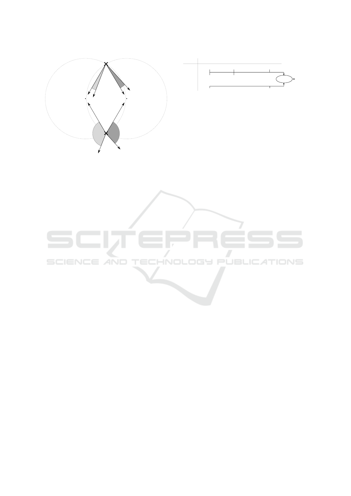
Figure 6 shows the approach for two observati-
ons Obs(t
1
) and Obs(t
2
). Intersecting them yields I
1
and I
2
as intersection points and therefore two loca-
tion candidates. To select the correct location out of
these two, we use the magnetometer azimuth readings
Obs(t
1
)
azi
and Obs(t
2
)
azi
. Although we argue that the
magnetometer is too inaccurate to represent the azi-
muth, it still points in the general direction and suffi-
ces to make the correct selection out of opposing can-
didates. We therefore calculate the expected azimuth
azi(t
i
, I
j
) of both intersection points for both points in
time using an astronomy library. The expected azi-
muth values are then compared to the ones yielded by
the magnetometer readings and the intersection with
least divergence is chosen. In Figure 6, the smaller
azimuth deviation at I
1
indicates that this is the correct
candidate, because the measured azimuth is closer to
the expected azimuth than at I
2
. We call the selected
candidate the intersection result.
5.4 Location Aggregation
In the previous section we showed how we compen-
sate azimuth inaccuracies and calculate device locati-
ons. If redundant measurements are available, we can
utilize them to mitigate altitude measurement errors
and thus improve the accuracy of geolocation. Redun-
dant measurements occur when the user keeps using
their mobile device even after we have computed one
observation Obs(t
i
).
Figure 7 shows how this redundancy integrates in
the whole approach. Instead of two measurements,
we perform k measurements for both points in time,
which allows us to perform k
2
circle intersections and
thus yields k
2
intersection results. We then select the
median latitude and the median longitude of all in-
Obs
1
(t
1
)
Obs
1
(t
2
)
Obs
2
(t
1
)
Obs
2
(t
2
)
Obs
k
(t
1
)
Obs
k
(t
2
)
...
Intersection
11
Average
Location
...
...
Intersection
12
Intersection
1k
Intersection
22
Intersection
21
Intersection
k1
...
...
... ...
...
... ...
Intersection
kk
...
Figure 7: Increasing accuracy by using redundant observa-
tions.
tersections as the final result. We refer to the whole
process as one location determination.
6 IMPLEMENTATION
We use a web-based prototype that collects sensor
data with the Ambient Light Sensor API (Kostiai-
nen et al., 2017) and DeviceOrientation API (Tibbett
et al., 2016). The implementation also records the de-
vice location as reported by the GPS-based Geoloca-
tion API (Popescu, 2016) for evaluation purposes to
determine the accuracy of the digital sextant. The pro-
cessing of the collected data is implemented in Python
and uses PyAstronomy (Czesla, 2013) as astronomy
library.
Dealing with Interferences. Reflections may inter-
fere with the result subject to the reflecting surface.
In one measurement series we found a light source at
an altitude < 0
◦
, which was due to a reflecting win-
dow board. While this is trivial to detect and filter,
reflections from perpendicular surfaces (for example
windows) are more challenging. In this case altitude
is not altered but azimuth will be misestimated and
can lead to an inaccurate location if the angle is large
enough. As a plausibility check we have implemented
a duplicate peak detection: if more than one signifi-
cant light source above a threshold (the sun and its
reflection) is found while searching the global maxi-
mum (cf. Section 5.2), the measurement will be mar-
ked as indecisive and rejected.
The sun threshold may vary between mobile devi-
ces due to different sensors used. If the device model
is known (e.g., based on the user agent), the threshold
can be preset subject to the sensor datasheet or to em-
pirical data. If the model is unknown, the threshold
can be set to 95% after collecting sensor data suffi-
ciently long, assuming that the sun has been recorded
eventually.
As our method requires exposure to direct sun-
light, being indoor or under a clouded sky prevents
geolocation. However, these cases can be identified
trivially as the sun is orders of magnitude brighter
on the Lux scale than other light sources. By pre-
filtering measurements for sunlight exposure we can
avoid mislocating the user in theses cases.
Mobile Devices as Digital Sextants for Zero-Permission Geolocation
59
0
2
4
6
8
10
12
14
16
5 6 7 8 9 10
Angular delta in °
Time in s
walking
standing
sitting
Figure 8: Impact of user behavior on accelerometer rea-
dings.
Table 1: Average angular velocity ω of various data sets.
Table Hand Sit Stand Walk
ω in
◦
s
10.41 27.44 115.70 157.04 229.80
7 PRACTICAL APPLICABILITY
An essential requirement of our method is to face the
sun, which leads to the question, whether this is rea-
listic during everyday smartphone activities. To pro-
vide an indication for the applicability we performed
the following tests with a Samsung Galaxy S7 running
Firefox for Android 48:
1. Stand with the sun in the back (standing)
2. Walk 25 m towards the sun, turn around and walk
25 m away from the sun (walking)
3. Sit with the sun in the back (sitting).
In each setting the test person looked at the smartp-
hone while touching, scrolling and reading the screen,
which causes the tilting phone to eventually face the
sun. Measurements were 40 seconds long and took
place in Duisburg, Germany on an unclouded day at
11:00, 13:00 and 15:00. Each altitude/azimuth obser-
vation has been repeated k = 5 times, which amounts
to a total of 45 measurements.
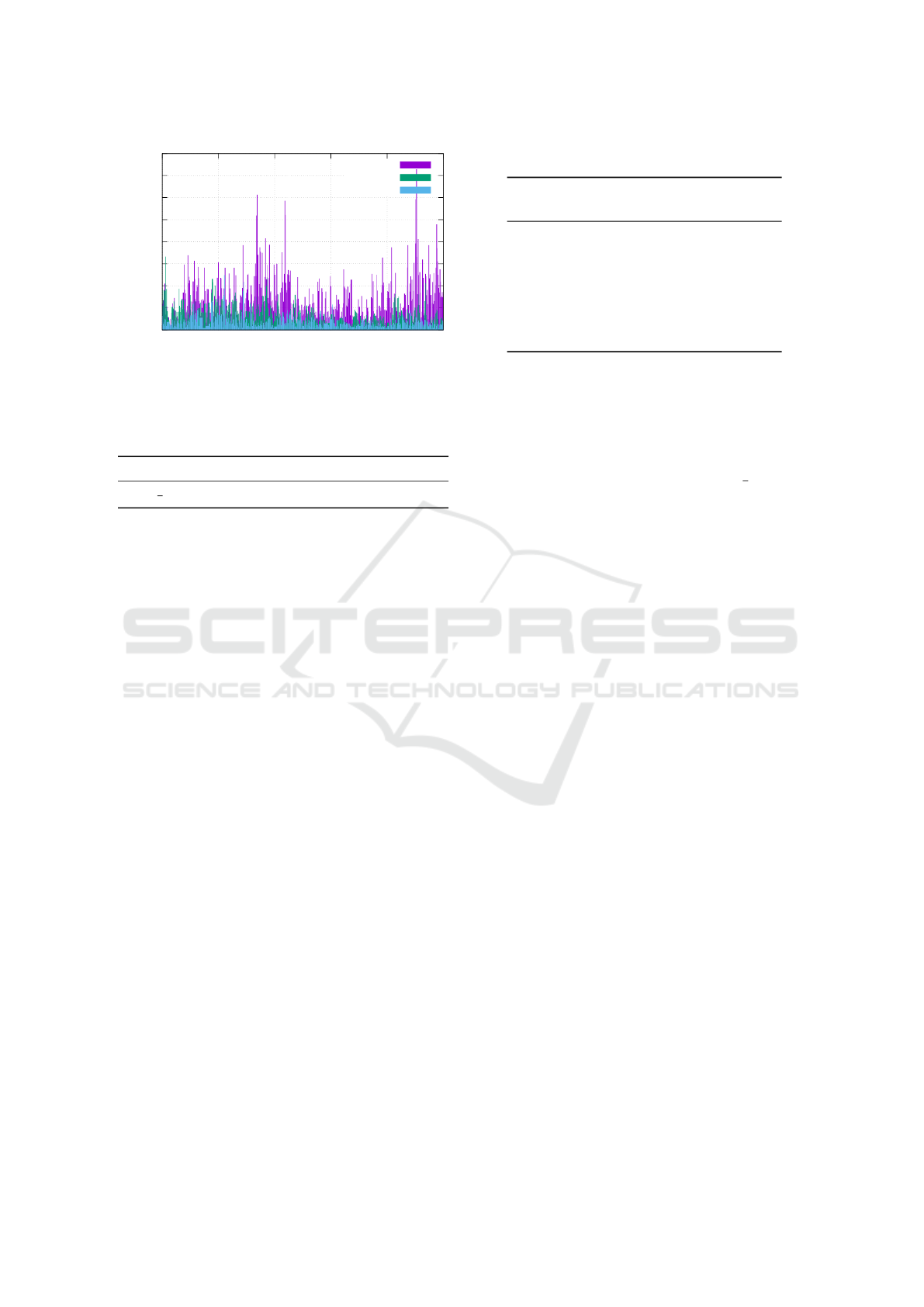
7.1 Movement Profiles
Figure 8 shows the angular difference between con-
secutive accelerometer vectors (data points) for an
excerpt of each test. We see that during walking
the smartphone moves more than during standing,
and during standing more than during sitting, leading
to different movement profiles. The sensor readings
are not only influenced by user movement, but also
Table 2: Accuracy in each test.
t
2
Error Spread
(km) (median/km)
Walk 13:00 1196.53 636.79
15:00 1083.73 424.73
Stand 13:00 808.98 960.48
15:00 777.08 231.13
Sit 13:00 380.24 300.79
15:00 146.43 131.44
by sensor jitter. This is demonstrated with two ot-
her tests: 1) the test person holds the smartphone in
their hand without deliberate movement (hand), 2) the
smartphone rests flat on a table (table). Table 1 shows
the average angular velocities of each test: the phone
resting on the table without any observable movement
measures an angular velocity of ω = 10.41
◦
s
, showing
that sensor jitter has indeed an influence.
7.2 Location Determination
We apply our approach to the 11:00 observations of
each test, paired with their corresponding observation
at t
2
two or four hours later. Table 2 shows the loca-
tion accuracy, i.e., the error of the determined loca-
tion compared with the actual location. We can see
a clear influence of movement profiles on accuracy:
as (unconscious) motions of the user are reduced, the
distance between determined and actual location re-
duces.
We conclude that while motion influences our ap-
proach, there are plausible scenarios that achieve an
accuracy usable for country-level geolocation, in spite
of sensor noise. A remaining open question is how of-
ten these scenarios occur with everyday smartphone
usage of unaware users. This depends on the users’
habits and we leave it for future work to collect sen-
sor data of multiple persons during everyday activities
to quantify the occasions for our geolocation method.
Based on the observation that too much macro
human movement deteriorates the accuracy, we can
restrict the method to run in situations with low-
movement profiles only. This can be achieved by ana-
lyzing angular velocity or by using an existing method
(Kwapisz et al., 2011) to determine the user’s current
activity.
8 SYSTEMATIC EVALUATION
Now that we have an indication for the practical ap-
plicability of our approach, we systematically analyze
ICISSP 2019 - 5th International Conference on Information Systems Security and Privacy
60
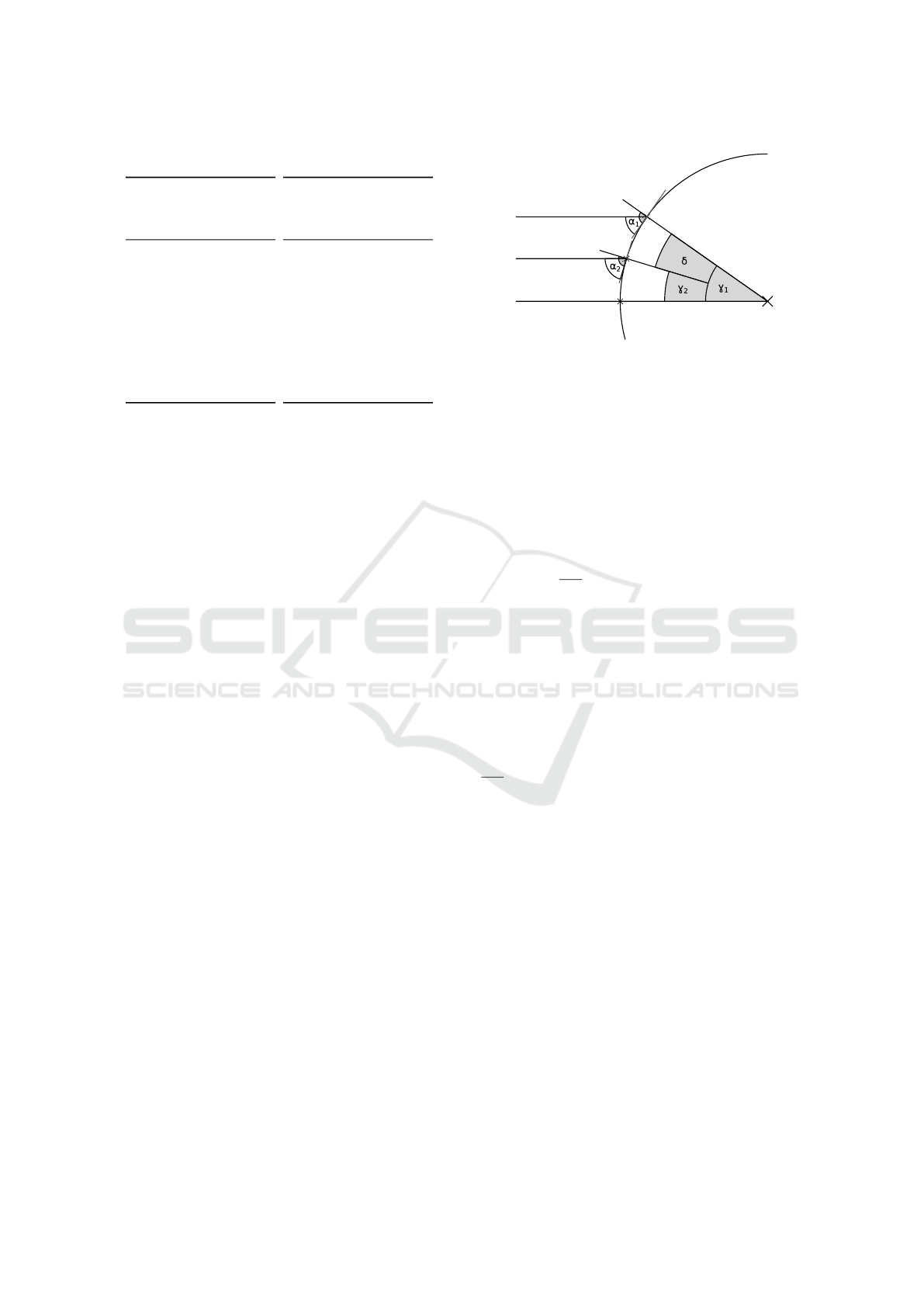
Table 3: Accuracy comparison of Nexus 7 and Galaxy S7.
Nexus 7
Error Spread
(km) (median/km)
154.1 592.9
174.7 426.1
326.5 208.1
360.9 243.6
456.2 239.5
463.4 258.5
464.3 329.0
527.7 390.6
1 052.4 353.5
1 993.8 487.3
Galaxy S7
Error Spread
(km) (median/km)
388.2 223.0
393.9 274.8
469.9 213.9
487.0 134.9
688.3 177.4
753.3 250.3
763.7 201.7
976.5 169.1
1 023.9 339.7
1 575.0 543.8
various factors that influence the geolocation accu-
racy. In the following measurements, we hold the mo-
bile device in one hand and tilt it in two dimensions
while pointing at the sun (cf. Figure 2).
We performed 10 location determinations in Duis-
burg, Germany with a Google Nexus 7 (2013) and
a Samsung Galaxy S7 running Firefox for Android
48. First measurements were conducted at noon, the
second ones two hours later at 14:00. Each alti-
tude/azimuth observation has been repeated k = 5 ti-
mes yielding a total of 100 measurements per device.
Our results are shown in Table 3. Column “Er-
ror” shows the error of 10 location determinations be-
tween our method and the true location as recorded by
the Geolocation API. Accuracy ranges from 154.1 km
to 1993.8 km with a median error of 459.8 km for
the Nexus 7. For the S7, the accurancy ranges from
388.2 km to 1575.0 km. While the error range is smal-
ler, the median error is 720.8 km and thus 56% higher
than for the Nexus 7.
Because each location determination consists of
k
2
= 25 redundant intersection results, we can exa-
mine the spread of these intermediate results as well.
Column “Spread” shows the median error to the cor-
rect position of all 25 intersection results for each lo-
cation determination. Interestingly, a larger spread
within each location determination does not negati-
vely impact the final accuracy. For example, the best
result of the Nexus 7 in the first row has the highest
spread of all location determinations for this device.
Systematically, accuracy and spread correlate weakly
with a Pearson correlation coefficient of r = 0.2367
for the Nexus 7. For the S7, this value is signifi-
cantly larger with r = 0.7553. We will discuss dif-
ferences of these devices and possible explanations in
Section 8.2. Since there is no general high correla-
tion between accuracy and spread, we conclude that
our approach is robust and is not easily influenced by
random measurement errors. In other words, each re-
Z
P
1
P
2
Sun rays
Figure 9: Location error depending on altitude.
dundant measurement contributes to the accuracy and
does not distort the final result.
8.1 Effect of Altitude Error
We now analyze the impact of an altitude estimation
error in order to determine the expected results with
more (or less) accurate sensors.
Analysis. Altitude alone—without considering non-
linear influences of circle intersection—yields a loca-
tion error of
δ
360
◦
E
circ
for an assumed altitude error of
δ. This can be derived from the Earth cross section di-
agram in Figure 9. Parallel sun rays reach Earth and
are correctly observed at P
1
with an altitude of α
1
.
Angular distance to the subsolar point Z (i.e., angu-
lar radius of the circle) amounts to γ
i
= 90
◦
− α
i
by
corresponding angles. In case there is an altitude es-
timation error and α
2
= α
1
+ δ is observed this will
yield an erroneous location P
2
. Solving these equati-
ons yields an angular distance between P
1
and P
2
of
δ = γ
1
− γ
2
which corresponds to a location offset by
δ
360
◦
E
circ
.
Simulation. To simulate the non-linear parts above
this lower error bound we created two groups of artifi-
cial observations with a time difference of two hours.
Each simulation initially assumes perfect altitude and
azimuth observations as computed by PyAstronomy
for this time and place. For each group we then ge-
nerate simulated observations with altitude deviations
of ±δ and a probing width of 0.25
◦
. Since we are
considering the worst case impact, we perform our
location determination approach on each pair out of
both groups and then use the maximum location error
as result.
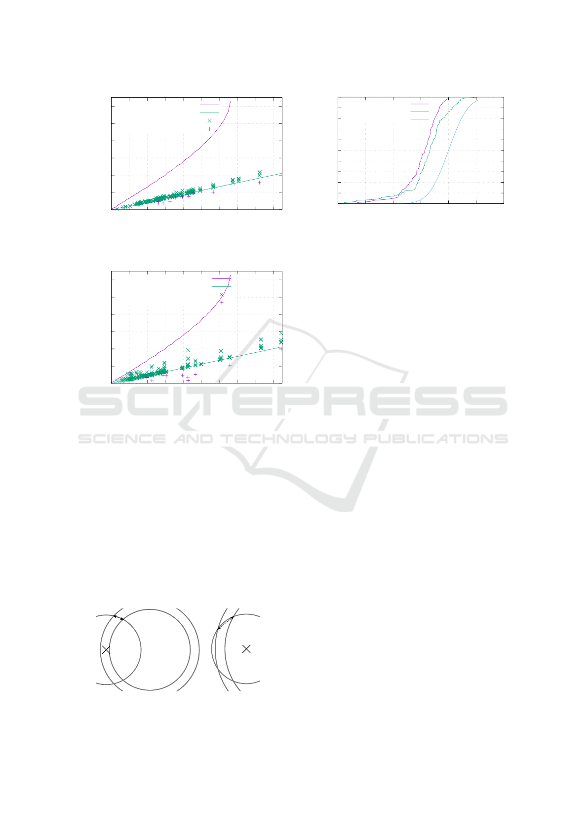
The results are presented in Figure 10 and Fi-
gure 11. The worst case location error is significantly
larger than the linear lower bound estimation. We can
also see the worst case gradient grows as altitude de-
viation increases, which means the maximum error is
non-linear. This is due to one circle growing so large
that it almost covers the other shrunken circle com-
Mobile Devices as Digital Sextants for Zero-Permission Geolocation
61
0
1000
2000
3000
4000
5000
6000
0 2 4 6 8 10 12 14 16 18
Positional deviation in km
Altitude deviation in degrees
Worst case simulation
δ 360
-1
E
circ
S7 intersection results
S7 final locations
Figure 10: Simulated worst case observations compared to
S7 based measurements.
0
1000
2000
3000
4000
5000
6000
0 2 4 6 8 10 12 14 16 18
Positional deviation in km
Altitude deviation in degrees
Worst case simulation
δ 360
-1
E
circ
Nexus 7 intersection results
Nexus 7 final locations
Figure 11: Simulated worst case observations compared to
Nexus 7 based measurements.
pletely. The effect is illustrated in Figure 12. The
small intersection angle cause any additional radius
difference/altitude deviation to yield an even higher
location error. Measurements with altitude deviations
greater than 13.5
◦
are not guaranteed to yield inter-
secting circles causing the result of the function to be
undefined thereafter.
Practical Evaluation. While the error could be very
high in theory, we now examine whether this has hap-
pened during our practical evaluation. Since we know
the correct altitudes in our experimental setup, we can
calculate altitude deviations for the intersection re-
sults (i.e., intersections before calculating a median
d
1
d
2
Figure 12: Effect of circles intersection angles on distance,
d
1
< d
2
.
0
0.1
0.2
0.3
0.4
0.5
0.6
0.7
0.8
0.9
1
-20 -15 -10 -5 0 5 10
Cumulative distribution function
Signed altitude deviation in degree
S7
Nexus 7
Normal distribution
Figure 13: Distribution of signed altitude deviation.
and yielding a final position) and final positions in
these figures. For each data point we aggregate the
altitudes of all involved observations as a maximum
to get a worst case view. In terms of location error the
measurements are close to the linear bound. This in-
dicates that the empirical average case is close to the
linear bound and that the theoretical worst case does
not occur in practice. Interestingly, the final positions
are below the linear threshold, suggesting that mea-
surement errors cancel each other out and thus redun-
dant measurements produce a more accurate location
result.
8.2 Systematic or Random Error
We now investigate why the results of the two mobile
devices scatter to a different extent and whether the
sensor error is random or systematic.
A difference between Figure 10 and Figure 11 lies
in the vertical spread of intersections. While they
stick to the lower limit in the former they spread more
towards the upper bound in the later. This means the
same absolute altitude deviation has a different impact
on both devices. To analyze this anomaly we took the
sign of the altitude deviation into consideration.
Figure 13 shows a cumulative error distribution
function of the signed altitude error for both devi-
ces. If deviations were merely due to random errors
we would assume a uniform distribution around 0.
Instead there is strong bias towards negative devia-
tions, i.e., measuring the sun at a lower position as
expected. The effect is even stronger on the Galaxy
S7, where we observed almost no positive deviations,
suggesting a device-specific systematic error. This
distinction also provides an explanation for increased
vertical spread: A positive deviation intersected with
a negative deviation yields a higher location error than
an intersection between two equally signed deviati-
ons. To verify this finding we removed intersections
with a positive deviation on Nexus 7 and plotted the
ICISSP 2019 - 5th International Conference on Information Systems Security and Privacy
62
0
1000
2000
3000
4000
5000
6000
0 2 4 6 8 10 12 14 16 18
Positional deviation in km
Altitude deviation in degrees
Worst case simulation
δ 360
-1
E
circ
Nexus 7 intersection results
Nexus 7 final locations
Figure 14: Simulated impact of altitude error on Nexus 7
without negative altitude deviated measurements.
result in Figure 14. The vertical variance has been
drastically reduced, which confirms a device-specific
systematic error.
This device-specific difference in altitude devia-
tion also provides a viable explanation for the diffe-
rent correlation coefficient outcomes from Section 8.
Since location determinations performed with the
Nexus 7 contain more outliers in the intersection re-
sults (see Figure 11), the results will have a higher
spread than with the Galaxy S7. We calculate a me-
dian out of these intersections to obtain the final po-
sition. Since medians are in general robust against
influences by outliers, there is no strong correlation
between the spread of a location determination and
its positional deviation on the Nexus 7.
This has implications for our redundancy parame-
ter k. If there is a systematic bias like for the Galaxy
S7, then additional measurements will not increase
the accuracy of our approach. On the other hand a
random error will be compensated by an increase of
k and successive averaging. Telling these errors apart
outside of an experimental setup where no correct al-
titude is known is non-trivial. If a systematic error de-
pended solely on the device model, an attacker could
classify various models and act accordingly. Howe-
ver, analyzing this dependency is outside the scope of
this paper.
8.3 Sensor Sampling Rate
Another difference between both mobile devices is
how often they provide new sensor values. We now
analyze whether this has an effect on our method.
Table 4 shows the sensor frequency per device
across all measurements from Section 8. Concerning
steadiness, the S7 performs better due to its signifi-
cantly lower standard deviation for both the ambient
light and acceleration sensor. This could be due to
the faster processor and the general technological ad-
Table 4: Frequency of sensor readings (Hz).
Nexus 7 Galaxy S7
¯x σ ¯x σ
Light sensor 3.67 1.30 5.61 0.04
Accelerator 192.60 2.37 99.09 0.41
vancements during the 3 years between the release
of both devices. Since our JavaScript implementa-
tion runs inside a web browser on top of a non-real-
time operating system, there are several components
involved being possible causes of this difference. The
frequency of the Nexus 7 light values scatters widely
with a standard deviation of 1.30 from its average of
3.67 Hz. However, this does not seem to affect our
method as the Nexus 7 achieves a better accuracy (cf.
Tab 3). The only sensor values more in favor of the
Nexus 7 are acceleration events per second, which are
nearly twice as frequent on the Nexus 7 than on the
S7. Although this correlates with a higher location
accuracy, it does not provide a plausible explanation.
Our approach uses both accelerometer and ambient
light readings to determine the altitude of the sun.
Even if the accelerometer frequency is doubled and
if the device orientation is more accurate, the lumi-
nance in that direction still lacks behind—especially
when the ambient light sensor has a low sampling fre-
quency.
9 COUNTERMEASURES
As the geolocation method bears the risk of violating
the user’s desire for privacy, we now investigate po-
tential countermeasures. An obvious remedy is to di-
sable sensor access completely for apps and for web-
sites. For example, the Orfox Browser
2
, a mobile Tor
Browser, restricts the use of any sensors and thus li-
mits the possibilities to leak information to websites.
While this prevents a whole class of sensor-based at-
tacks, it also limits the potential of the Web as an ap-
plication platform. Likewise, iOS does not expose an
API to access ambient light sensor values preventing
our attack on that platform.
Another remedy is to artificially reduce the sensor
resolution to provide a compromise between privacy
concerns and legitimate use cases. We analyze this
possibility by truncating the sensor data of the Nexus
7 from Section 8, both regarding ALS and accelero-
meter. The truncation consists of rounding sensor rea-
dings to next multiples of a variable sensor truncation
factor ε. This simulates a sensor with a reduced reso-
lution.
2
https://guardianproject.info/apps/orfox/
Mobile Devices as Digital Sextants for Zero-Permission Geolocation
63
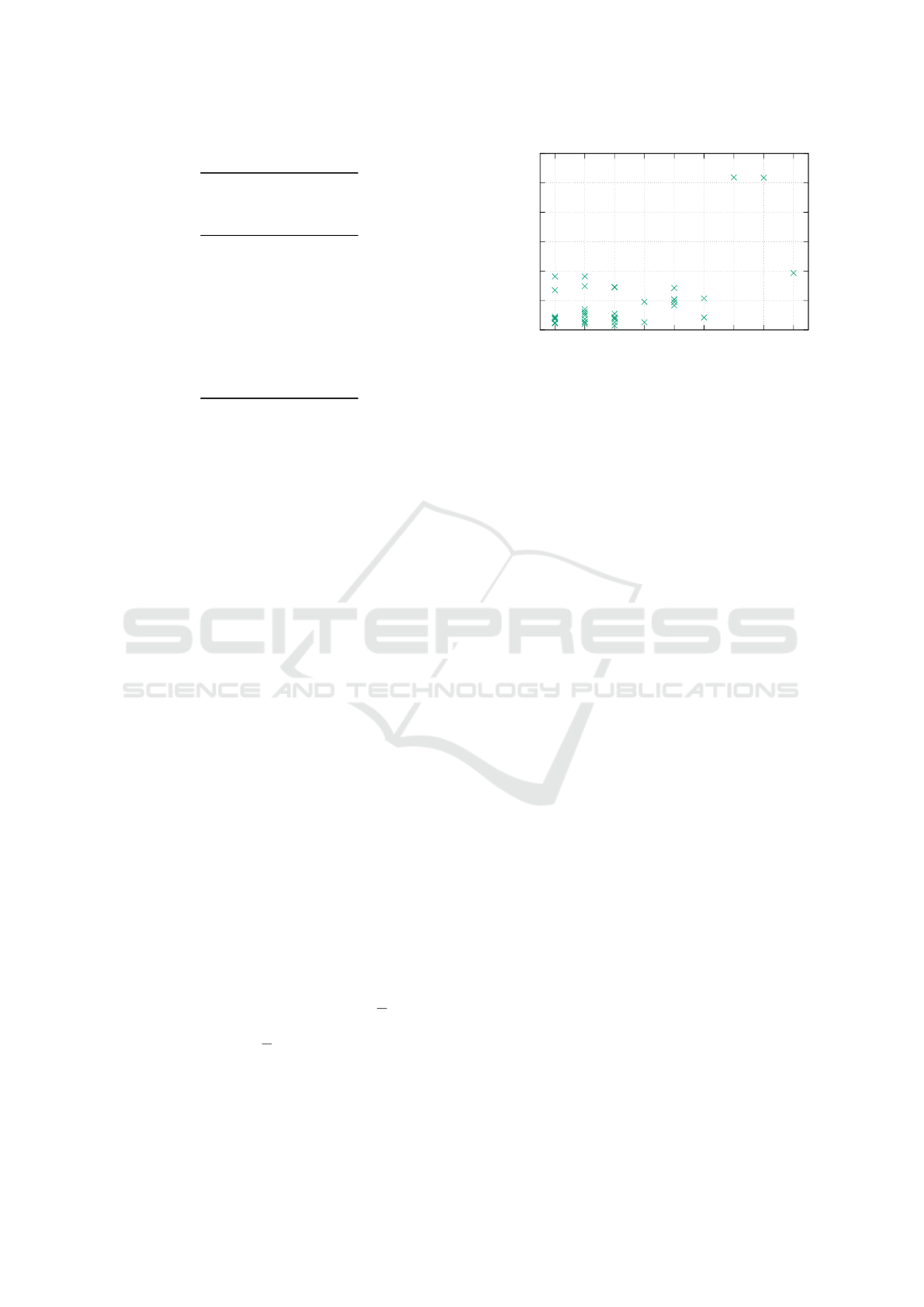
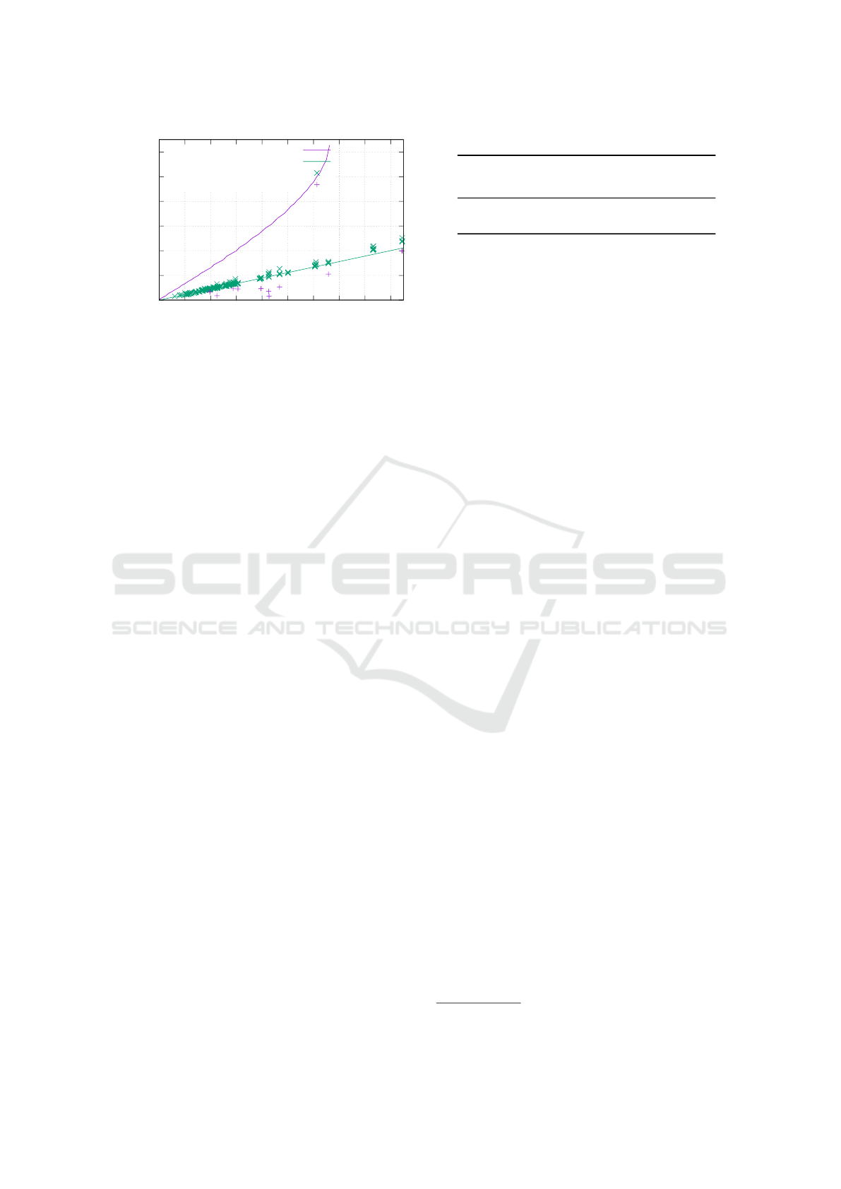
Table 5: Accuracy with ALS truncated to binary scale.
Nexus 7
Distance Spread
(km) (median/km)
104.7 378.8
230.6 375.7
318.7 176.0
361.2 269.3
382.0 235.6
449.8 366.1
460.8 347.4
487.1 370.0
979.4 628.7
2 736.2 1 112.5
9.1 Ambient Light Sensor
Reducing the ALS resolution has been shown to pre-
vent information leakage in other use cases (Schwitt-
mann et al., 2016). Interestingly, our approach did
not yield significantly worse results while iteratively
increasing the truncation factor ε.
In extreme case, we round the ambient light sensor
readings to binary values. Table 5 shows the results
of such a binary truncation. Compared with regular
results from Table 3 the results have shifted: while
the average location error increased slightly by 9%,
some results have become more accurate.
Although this result appears surprising, it is re-
asonable due to how our approach works. The sun
is significantly brighter than everything else recorded
like diffuse reflections or artificial lighting. This will
cause all values to become 0 except those measure-
ments directly pointed towards the sun. Our inverse
distance weighting will then yield the center of these
points as the altitude. As potential interferences do
not pass the binarization filter, some results become
more accurate while others become worse due to a
loss of information.
From these results we conclude that reducing ALS
resolution definitely does not provide an obstacle for
our approach.
9.2 Accelerometer
Similarly, we simulate the impact of truncating the
3D accelerometer on location accuracy with trunca-
tion factors of ε ∈ {1, 2,3, 4, 5, 6, 7, 8, 9}
m
s
2
. To put
these values into perspective with Earth’s gravitatio-
nal acceleration of 9.81
m
s
2
, the coarsest sensor resolu-
tion in our simulation should only be able to differen-
tiate rotations multiple of 90
◦
.
Figure 15 visualizes the simulation output. While
up to ε = 4 the median location error does not become
0
1000
2000
3000
4000
5000
6000
1 2 3 4 5 6 7 8 9
Positional deviation in km
ε in m/s²
Figure 15: Impact of truncated accelerometer resolution.
significantly worse, the number of successful location
determinations drops as ε increases. This is due to ob-
servational circles not intersecting when the altitude
error is too large or due to contradicting global max-
ima caused by the threshold function.
This shows that a truncation of the accelerometer
impairs the geolocation approach, but may still leak
coarse information with a large error to an attacker.
10 RELATED WORK
The user’s location is generally regarded as a privacy-
sensitive information with a large body of research
dedicated to ways of utilizing various available sour-
ces to infer it.
Locating a device by looking up its IP address in a
database is a heuristic implemented by various com-
mercial products. The observation behind this appro-
ach is that Internet service providers distribute IP ad-
dresses in geographical proximity. While this appro-
ach is straightforward once a database has been crea-
ted, it fails when a privacy-aware user employs techni-
ques to obfuscate their IP address (e.g., VPN, proxy
server, Tor).
Powerspy (Michalevsky et al., 2015) derives the
location from the phone power meter, which is avai-
lable without special permissions in the Android API.
Cellular radio power consumption depends on loca-
tion due to obstructions and cellular tower placement
allowing trajectory reconstructions using a dedicated
coverage database. While providing more accurate
results than our approach, it bears additional requi-
rements: both an app has to be installed on the device
and the user has to move in a coverage charted area.
Using camera images is another way of locating
a user. It is feasible (Guan et al., 2013) to determine
positions in a city by reading camera images and in-
ertial sensors. Taking the sun into consideration (Ma
ICISSP 2019 - 5th International Conference on Information Systems Security and Privacy
64

et al., 2017) it is possible to locate a user on a map.
Both approaches show remarkable accuracies but re-
quire camera permissions. A privacy-aware user is
unlikely to grant this to a dodgy website or app.
In some scenarios inertial sensors alone provide
enough information to locate users, if users move al-
ong given paths. Metro lines (Hua et al., 2017) have
distinctive accelerations patterns allowing to track
users. ACComplice (Han et al., 2012) uses solely
the accelerometer to identify car trajectories in trai-
ned data. Another approach uses magnetometer and
gyroscope readings (Narain et al., 2016) to locate a
car using publicly available cartographic data without
any training. While this increases practical applicabi-
lity, feasibility on a global scale remains open. Com-
pared to our approach this also requires cartographic
material which might not be available for the subject’s
location.
Wi-Fi BSSID-based approaches are a standard
way of locating smart devices. Even without access
to the operating systems’s BSSID queries, an android
application without location permission can read the
BSSID of the connected access point and perform its
own BSSID lookup on application level (Zhou et al.,
2013). Another side channel discovered by Zhou
et al. consists of the speaker API. Every application
can query whether any other application is currently
playing sounds. Originally designed to provide apps
with means of coordination, this allows to measure
playback duration and deduce announcements made
by a GPS navigation app.
Ambient light has been considered as well for lo-
cation determination. SurroundSense (Azizyan et al.,
2009) looks at a combination of ambient sound, light
and color to acquire fine-grained location fingerprints
to distinguish shops in a mall. Epsilon (Li et al., 2014)
uses visible light beacons that are broadcasting their
position. High frequency pulse width modulations
on LED bulbs makes this flickering indistinguisha-
ble from dimming to the human eye. While both ap-
proaches promote non-malicious use cases, especially
Epsilon is suited to violate the user’s privacy since it
could be implemented using a zero-permission app or
website. However, it would require to deploy an in-
frastructure of beacons to track users.
11 CONCLUSIONS
In this paper we have presented a novel approach to
locate mobile devices using sun-based measurements.
The approach utilizes mobile device sensors that are
accessible on platforms like Android without asking
the user for permission. Unlike related work, a prior
training or cartography of the user’s area is not neces-
sary, as we are relying on the well-known movement
of celestial bodies.
In our experimental evaluation we achieved a me-
dian accuracy of better than 500 km, which is suf-
ficient for country-level geolocation. The location
accuracy will improve with more accurate sensors in
mobile devices. Our analysis has shown that both
random and systematic sensor errors influence the re-
sult, where the random error portion can be minimi-
zed by utilizing redundant measurements.
For future work we would like to improve our ap-
proach to cope with indirect sunlight. So far we rely
on direct exposure to calculate altitude and azimuth.
With an advanced sky model and sensor calibration it
could be possible to estimate altitude based on a path
not intersecting or tangent to the sun.
Privacy. In line with previous work in this field,
our zero-permission geolocation approach once again
shows that it is unforeseeable what high-level infor-
mation might be concluded from seemingly harmless
sensor values. One way to cope with this threat in ge-
neral is to truncate sensor readings by default, which
helps to preserve privacy in several cases while still
providing a value to legitimate applications.
In our case, truncating the ambient light sensor has
almost no effect on location accuracy and thus does
not help. Truncation of the accelerometer worsens
the accuracy and number of location determinations
when rounded to multiples of 4 or more. Such an im-
pairment likely affects legitimate use cases, thus que-
stioning the adequacy of such a tradeoff.
A mitigation strategy might be to ask the user for
permission before allowing sensor access at all—not
for individual sensors as this affects the usability, but
for a group of sensors that are less privacy-invading
than camera or microphone access while still revea-
ling some contextual information about the user, in-
cluding accelerometer, barometer, magnetometer and
ambient light sensor. An important element would be
to disclose to the user what information is being col-
lected and what it is used for. A technical enforce-
ment combined with a documented privacy policy al-
lows users to make an informed choice whether they
approve the disclosure of contextual information.
REFERENCES
Azizyan, M., Constandache, I., and Roy Choudhury, R.
(2009). Surroundsense: Mobile phone localization via
ambience fingerprinting. In Proceedings of the 15th
Annual International Conference on Mobile Compu-
ting and Networking, MobiCom ’09, pages 261–272,
New York, NY, USA. ACM.
Mobile Devices as Digital Sextants for Zero-Permission Geolocation
65

Blum, J. R., Greencorn, D. G., and Cooperstock, J. R.
(2012). Smartphone sensor reliability for augmented
reality applications. In International Conference on
Mobile and Ubiquitous Systems: Computing, Networ-
king, and Services, pages 127–138. Springer.
Czesla, S. (2013). PyAstronomy. https://github.com/
sczesla/PyAstronomy. Accessed on 2018-05-16.
Guan, T., He, Y., Gao, J., Yang, J., and Yu, J. (2013). On-
device mobile visual location recognition by integra-
ting vision and inertial sensors. IEEE Transactions on
Multimedia, 15(7):1688–1699.
Han, J., Owusu, E., Nguyen, L. T., Perrig, A., and Zhang, J.
(2012). Accomplice: Location inference using acce-
lerometers on smartphones. In Ramakrishnan, K. K.,
Shorey, R., and Towsley, D. F., editors, Fourth Inter-
national Conference on Communication Systems and
Networks, COMSNETS 2012, Bangalore, India, Janu-
ary 3-7, 2012, pages 1–9. IEEE.
Hua, J., Shen, Z., and Zhong, S. (2017). We can track you if
you take the metro: Tracking metro riders using acce-
lerometers on smartphones. IEEE Transactions on In-
formation Forensics and Security, 12(2):286–297.
Kostiainen, A., Langel, T., and Turner, D. (2017).
Ambient light sensor. W3C working draft,
W3C. https://www.w3.org/TR/2017/WD-ambient-
light-20170814/.
Kwapisz, J. R., Weiss, G. M., and Moore, S. A. (2011).
Activity recognition using cell phone accelerometers.
SIGKDD Explor. Newsl., 12(2):74–82.
Li, L., Hu, P., Peng, C., Shen, G., and Zhao, F. (2014). Ep-
silon: A visible light based positioning system. In
11th USENIX Symposium on Networked Systems De-
sign and Implementation (NSDI 14), pages 331–343,
Seattle, WA. USENIX Association.
Li, Z., Pei, Q., Markwood, I., Liu, Y., Pan, M., and Li, H.
(2018). Location privacy violation via gps-agnostic
smart phone car tracking. IEEE Transactions on Vehi-
cular Technology, pages 1–1.
Ma, W. C., Wang, S., Brubaker, M. A., Fidler, S., and Ur-
tasun, R. (2017). Find your way by observing the sun
and other semantic cues. In 2017 IEEE International
Conference on Robotics and Automation (ICRA), pa-
ges 6292–6299.
Michalevsky, Y., Schulman, A., Veerapandian, G. A., Bo-
neh, D., and Nakibly, G. (2015). Powerspy: Location
tracking using mobile device power analysis. In 24th
USENIX Security Symposium (USENIX Security 15),
pages 785–800, Washington, D.C. USENIX Associa-
tion.
Narain, S., Vo-Huu, T. D., Block, K., and Noubir, G.
(2016). Inferring user routes and locations using zero-
permission mobile sensors. In 2016 IEEE Symposium
on Security and Privacy (SP), pages 397–413.
Popescu, A. (2016). Geolocation API specification
2nd edition. W3C recommendation, W3C.
https://www.w3.org/TR/2016/REC-geolocation-
API-20161108/.
Schwittmann, L., Matkovic, V., Wander, M., and Weis, T.
(2016). Video recognition using ambient light sensors.
In 2016 IEEE International Conference on Pervasive
Computing and Communications (PerCom), pages 1–
9.
Tibbett, R., Volodine, T., Block, S., and Popescu,
A. (2016). Deviceorientation event specifica-
tion. W3C candidate recommendation, W3C.
https://www.w3.org/TR/2016/CR-orientation-event-
20160818/.
Triukose, S., Ardon, S., Mahanti, A., and Seth, A. (2012).
Geolocating IP Addresses in Cellular Data Networks,
pages 158–167. Springer Berlin Heidelberg, Berlin,
Heidelberg.
Zhou, X., Demetriou, S., He, D., Naveed, M., Pan, X.,
Wang, X., Gunter, C. A., and Nahrstedt, K. (2013).
Identity, location, disease and more: Inferring your
secrets from android public resources. In Proceedings
of the 2013 ACM SIGSAC Conference on Computer
& Communications Security, CCS ’13, pages 1017–
1028, New York, NY, USA. ACM.
ICISSP 2019 - 5th International Conference on Information Systems Security and Privacy
66
