
Experimental Measurement of Angular Anisoplanatism for Sodium
Laser Guide Star: Synchronized Range Gating Realization
Xi Luo, Xinyang Li, Xiaoyun Wang and Kui Huang
The Laboratory on Adaptive Optics, Institute of Optics and Electronics, Chinese Academy of Sciences, P. O. Box 350,
Shuangliu, Chengdu, Sichuan 610209, China
The Key Laboratory on Adaptive Optics, Chinese Academy of Sciences, P. O. Box 350,
Shuangliu, Chengdu, Sichuan 610209, China
Keywords: Adaptive Optics, Sodium Laser Guide Star, Angular Anisoplanatism, Range Gating Mechanism,
Synchronized Timing Control, Experimental Measurement.
Abstract: Laser Guide Star (LGS) is an ideal synthetic beacon of Adaptive Optics (AO) for compensating for the
atmospheric turbulence induced wave-front distortion of the science object; however the unavoidable
anisoplanatism resulting from different light experience between the LGS and the science object through
turbulent atmosphere will lead to a degradation of compensation performance, especially for the angular
anisoplanatism in sodium LGS AO. By using our developed Hartmann-Shack (HS) wave-front sensor with
accurate range gating mechanism, the return-light spot arrays through turbulent atmosphere from the natural
star and the excited sodium LGS with certain angular offsets can be synchronously collected. Different from
our previously published work (Luo et al., 2018), the experimental set-up, the structural design of the range
gating mechanism, and the timing design of the synchronized control are discussed emphatically in this
paper. The typical experimental measurement result of the angular anisoplanatism for the sodium LGS with
10” angular offsets is just briefly presented, which is basically consistent with our previous numerical
simulation result (Luo et al., 2015). The majority of Zernike-modal de-correlations between the sodium
LGS and the science object occur obviously, as the sodium LGS reference moving outside of the optical
path from the science object to the telescope aperture.
1 INTRODUCTION
Adaptive Optics (AO) applied for compensating for
turbulent atmosphere in real time usually requires a
sufficiently bright reference source in the isoplanatic
patch around the science object to provide a desired
measurement of the wave-front distortion induced
from atmospheric turbulence. The concept of Laser
Guide Star (LGS) has been publicly proposed to
overcome the limitations due to finite sky-coverage
(Foy and Labeyrie, 1985), which is generated by
illuminating a ground-based laser in the specific
atmosphere layer to provide the backscattered light
with information on the wave-front distortion
introduced by atmospheric turbulence, including the
Rayleigh LGS (Fugate et al., 1991) and the sodium
LGS (Humphreys et al., 1991). Profiting from its
higher altitude with better sampling of atmospheric
turbulence, the sodium LGS has been received
worldwide attention since its concept was first put
forward (Fugate et al., 1994; Bonaccini, Hackenberg,
and Avila, 1998; Joyce, et al., 2006).
Anisoplanatism results from different turbulence
experience along the optical path by light from the
LGS and the science object, which is one of the
fundamental limitations to preventing an ideal LGS
AO performance. Since atmospheric turbulence
strength is distributed and varied with altitude in
front of the aperture of receiving telescope,
comparing with focal anisoplanatism just induced
from the finite altitude for the LGS reference
coinciding with the science object, angular
separation (namely, angular anisoplanatism) results
in two lights traversing different regions in
atmospheric turbulence, and arises an deterioration
of the partial Zernike-modal correlations between
the LGS reference and the science object, especially
for the sodium LGS with greater angular separation.
As the theoretical investigation has progressed
(Molodij and Rousset, 1997; Sasiela, 2007), with the
rapid development of the sodium LGS technology
102
Luo, X., Li, X., Wang, X. and Huang, K.
Experimental Measurement of Angular Anisoplanatism for Sodium Laser Guide Star: Synchronized Range Gating Realization.
DOI: 10.5220/0007308401020109
In Proceedings of the 7th International Conference on Photonics, Optics and Laser Technology (PHOTOPTICS 2019), pages 102-109
ISBN: 978-989-758-364-3
Copyright
c
2019 by SCITEPRESS – Science and Technology Publications, Lda. All rights reserved

and its application in engineering, also the
experimental investigations on the sodium LGS
anisoplanatism have been carried out. For example,
the experimental measurement of anisoplanatic
degradation of K-band Strehl ratio on the 10-m Keck
II telescope (Van Dam et al., 2006), the
experimental measurement of focal anisoplanatism
carried out by China Academy of Engineering
Physics (Chen et al., 2015), etc.. However, to the
best of our knowledgement, there has been no public
report on the quantitative measurements of angular
anisoplanatic error for the sodium LGS in literature.
By using our developed HS wave-front sensor with
accurate range gating actualization, the synchronized
experimental measurement of angular anisoplanatic
effect for the sodium LGS can be achieved.
The emphasises of this paper are on the
discussions of the experimental set-up, the structural
design of the range gating mechanism, and the
timing design of the synchronized control. In order
to maintain the integrity of this paper, the typical
experimental results of the wave-front distortion
decomposed Zernike-modal correlations between the
natural star and the sodium LGS reference with 10”
angular offsets, and the angular anisoplanatism
decomposed Zernike-modal relative errors for the
off-axis sodium LGS reference are just briefly
presented. For the detailed disscusion of the
achieved angular anisoplanatism experimental data,
readers could find answer in our previously
published work (Luo et al., 2018).
2 EXPERIMENTAL SET-UP
The experimental set-up of synchronized angular
anisoplanatism measurement for sodium LGS is
outlined in Figure 1, which includes the telescope
with clear aperture of 1m, the pulsed sodium LGS
laser source with wavelength centered on the
mesospheric sodium D
2
line, the Tilt Mirror (TM)
for pointing control of the sodium LGS laser source
projection to sky, the synchronized control module,
the developed HS wave-front sensor with accurate
range gating mechanism, and the corresponding
processor for the wave-front recovery and the TM
actuation.
As shown in Figure 1, in the experiment, the
telescope works in closed-loop to track an
appropriate natural star in the sky with azimuth
angle A and elevation angle E, and the incident laser
beam of the sodium LGS laser source is reflected off
the TM and projected to the mesospheric layer for
generating the resonant backscattered sodium LGS
with its angular distance θ from the natural star
closed-loop controlled by the TM. On the basis of
the synchronized control reference signal provided
from the HS wave-front sensor, in every laser shot,
the temporal synchronization of the laser source
emission and the resulting resonant backscattered
sodium LGS detection with the HS wave-front
sensor can be achieved via the synchronized control
module. Consequently, two sets of the synchronous
wave-front distortion sequences can be recovered
with the return-light spot arrays through turbulent
atmosphere from the on-axis natural star and the off-
axis sodium LGS. Furthermore, the anisoplanatic
error’s Zernike-modal statistics for the off-axis
sodium LGS can be derived from the two sets of the
recovered wave-front distortion sequences.
2.1 HS Wave-front Sensor with
Accurate Range Gating
Actualization
The schematic diagram of the HS wave-front sensor
is illustrated in Figure 2, along the direction of the
return-light propagation, which consists of the beam
compressing optical system with compression ratio
of 6:1, the mechanical shutter device, the microlens
array, the matched imaging optical system with
magnification of 2:1, and the Charge Coupled
Device (CCD) camera. The corresponding field of
view of each sub-aperture is 21.9”.
In our developed HS wave-front sensor, the
adoption of mechanical shutter technology is an
effective way to selecting the resonant backscatter
from the sodium atoms in the mesospheric layer (at
the altitude of approximately 80~100km), and
meanwhile to obstructing the Rayleigh backscatter
from the air molecules in the short-range atmosphere
(at the altitude of approximately below 30km).
As shown in Figure 2 and Figure 3, the
mechanical shutter device includes the photoelectric
switch sensor, the rotary optical-chopping disc and
its motor driven. The rotary optical-chopping disc is
vertically mounted at the optical focus of entry lens
of the beam compressing optical system. For the
repetitively pulsed sodium resonant backscattered
light unobstructed propagation and collection, there
are a number of slots with central angle φ are
rotational-symmetrically manufactured on the edge
of the optical-chopping disc. In practice, the number
of the slots M depends on the output pulse repetition
frequency of the sodium LGS laser source f and an
appropriate rotational speed of the optical-chopping
disc N (namely, M×N=f). At the same time, the
output pulse-width of the sodium LGS laser source
Experimental Measurement of Angular Anisoplanatism for Sodium Laser Guide Star: Synchronized Range Gating Realization
103

Figure 1: The experimental set-up of synchronized angular anisoplanatism measurement for sodium LGS.
Δt
Pulse
, the sampled thickness of the sodium layer ΔH,
the accommodation to the elevation angle E
variation for the sodium LGS observation, and the
transition time from the open-started state to the
open-completed state of the receiving optical path of
the HS wave-front sensor Δt
rising
must be taken into
account in the design of the central angle φ of every
single slot on the optical-chopping disc (namely,
φ≥(2×ΔH/sinE/c+Δt
pulse
+Δt
rising
) ×N×360).
As the optical-chopping disc stably rotates, the
receiving optical path on-off state of the HS wave-
front sensor is periodically modulated, and the
synchronized control reference signal of the same
frequency as the sodium LGS laser source emission
is obtained from the photoelectric switch sensor
reading the slots on the disc, whose duty cycle
equals to (φ×f)/(N×360). Based on this synchronized
control reference signal, the sodium LGS laser
Figure 2: The schematic diagram of the HS wave-front sensor with range gating mechanism.
PHOTOPTICS 2019 - 7th International Conference on Photonics, Optics and Laser Technology
104
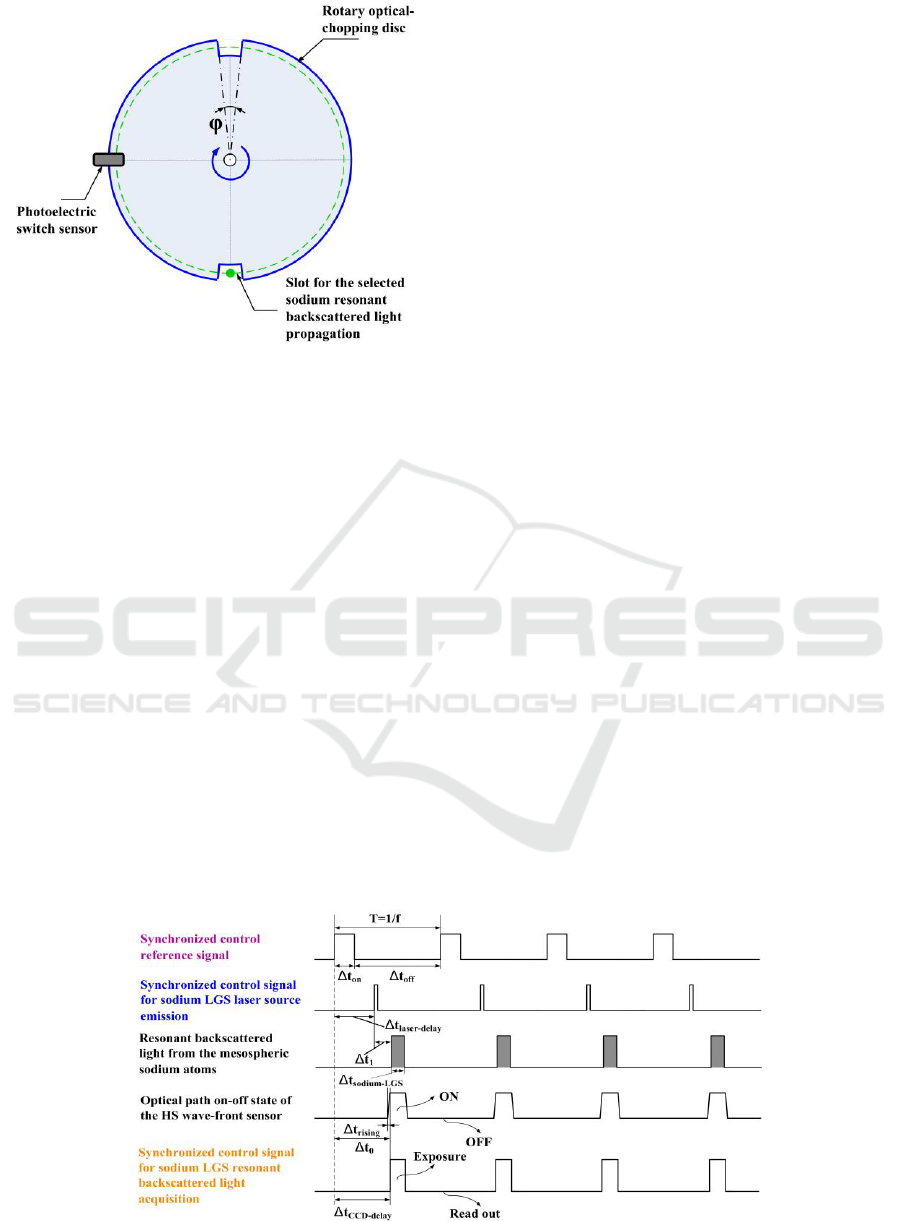
Figure 3: The schematic diagram of the mechanical shutter
device.
source emission and the resulting resonant
backscattered sodium LGS detection with the CCD
camera can be temporally synchronized. Within
every launch period of the sodium LGS laser source,
it is synchronously confirmed that the receiving
optical path is not in completely on state until the
resonant backscattered light resulting from the
interaction between the emitted laser pulse and the
mesospheric sodium atoms arrives at the aperture of
the telescope.
2.2 Synchronized Control Process for
Sodium LGS Laser Source
Emission and Its Resulting
Resonant Backscattered Light
Collection
In order to select the resonant backscatter from the
sodium atoms in the mesospheric layer and to
obstruct the Rayleigh backscatter from the air
molecules in the short-range atmosphere by
effectively range gating, the synchronized control
process for the pulsed sodium LGS laser source
emission and its resulting resonant backscattered
light collection is designed.
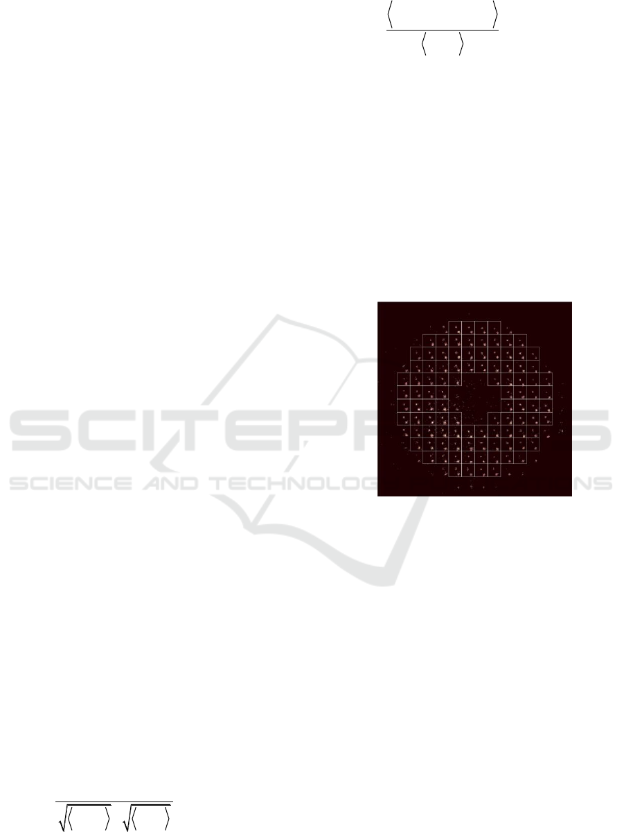
In Figure 4 the synchronized control process for
the pulsed sodium LGS laser source emission and its
resulting resonant backscattered light collection is
outlined:
(1) Δt
on
=φ/(N×360) is the high level duration of
the synchronized control reference signal obtained
from the photoelectric switch sensor;
Δt
1
=2×H
begin
×cscE/c is the arrive time of the
resonant backscattered light from the bottom of the
sodium layer at the altitude of H
begin
after each laser
pulse emitting; Δt
sodium-LGS
=2×ΔH×cscE/c+Δt
pulse
is
the temporal duration of the resonant backscattered
light resulting from the interaction between the
sodium atoms in the mesospheric layer and the
emitted laser pulse with pulse-width of Δt
pulse
.
(2) Δt
rising
is the transition time from the open-
started state to the open-completed state of the
receiving optical path of the HS wave-front sensor;
Δt
0
is the time delay between the rising edge of the
synchronized control reference signal and the open-
completed state of the receiving optical path of the
HS wave-front sensor; both of them can be
accurately measured in advance by high-speed
photodetector and oscilloscope.
(3) Δt
laser-delay
=Δt
0
‒Δt
1
is the time delay between
the rising edge of the synchronized control reference
signal and the rising edge of the synchronized
control signal for the pulsed sodium LGS laser
source emission; Δt
CCD-delay
=Δt
0
is the time delay
between the rising edge of the synchronized control
reference signal and the rising edge of the
synchronized control signal for the sodium LGS
resonant backscattered light exposure by the CCD
camera.
Figure 4: The designed timing diagram of the sodium LGS resonant backscattered light synchronized collection.
Experimental Measurement of Angular Anisoplanatism for Sodium Laser Guide Star: Synchronized Range Gating Realization
105
3 POST-PROCESSING OF
EXPERIMENTAL DATA
Based on the experimental set-up (as shown in
Figure 1), the structural design of the mechanical
shutter device (as shown in Figure 3), and the timing
design of the sodium LGS synchronized collection
(as shown in Figure 4), as time goes by, the
sequences of the return-light spot arrays through
turbulent atmosphere from the natural star and the
sodium LGS with certain angular offsets can be
synchronously collected by the HS wave-front
sensor.
Afterwards, from the mutiple-frame sequences of
the return-light spot arrays collected by the HS
wave-front sensor, the synchronous turbulence-
induced wave-front distortion sequences can be
recovered for the on-axis natural star and the off-
axis sodium LGS, respectively:
K
STAR j STAR j
j3
K
LGS j LGS j
j4
Rr a Z r
Rr a Z r
,,
, , ,
(1)
where R is the clear aperture radium of the telescope,
Z
j
(r,ϑ) is the j th-order Zernike polynomial (Noll,
1976), a
j-STAR
is the decomposed j th-order Zernike-
modal coefficient of the wave-front distortion of the
on-axis natural star, a
j-LGS
is the decomposed j th-
order Zernike-modal coefficient of the wave-front
distortion of the off-axis sodium LGS, and K is the
corresponding highest-order Zernike mode of the
recovered wave-front distortion by the HS wave-
front sensor (e.g. K=35). The total-tilt terms (e.g.
j=1, 2) for the on-axis natural star, and the total-tilt
and defocus terms (e.g. j=1, 2, 3) for the off-axis
sodium LGS are not included in the recovered wave-
front distortion.
Consequently, the recovered wave-front
distortion decomposed Zernike-modal correlations
between the on-axis natural star and the off-axis
sodium LGS, and the angular anisoplanatism
decomposed Zernike-modal relative errors for the
off-axis sodium LGS can be calculated by the
equation (2) and equation (3), respectively:
j STAR j LGS
j STAR j LGS
j
22
COV a ,a
r j 4
aa
(2)
j STAR
2
j STAR j LGS
2
j
2
aa
ε j 4
a
(3)
where COV denotes the covariance, and < > denotes
the ensemble average.
4 TYPICAL EXPERIMENTAL
RESULTS
In this section, for the integrity of this paper, we just
briefly present the typical experimental result of
angular anisoplanatism measurement for the sodium
LGS with 10” angular offsets, which has been
partially published in our previous work (Luo et al.,
2018).
Figure 5: The typical single frame of the return-light spots
arrays from the natural star and the sodium LGS with 10”
angular offsets (Luo et al., 2018).
H
begin
is chosen to be 75km for timing rejection
of the Rayleigh back scattering. The typical single
frame of the return-light spot arrays through
turbulent atmosphere from the natural star with
azimuth angle A of 70
o
and elevation angle E of 75
o
and the sodium LGS with 10” angular offsets is
shown in Figure 5 (Luo et al., 2018), the whole
return-light spot arrays from the natural star are
located at the center of the sub-apertures, and the
whole return-light spot arrays from the sodium LGS
with 10” angular offsets are located at the bottom
right of the sub-apertures.
The first 20th Zernike-modal correlations of the
recovered wave-front distortion between the on-axis
natural star and the off-axis sodium LGS with 10”
angular offsets are calculated and shown in Figure 6.
Good correlations only exist in the low-order
Zernike modes of the two types of wave-front
distortions from the on-axis natural star and the off-
PHOTOPTICS 2019 - 7th International Conference on Photonics, Optics and Laser Technology
106
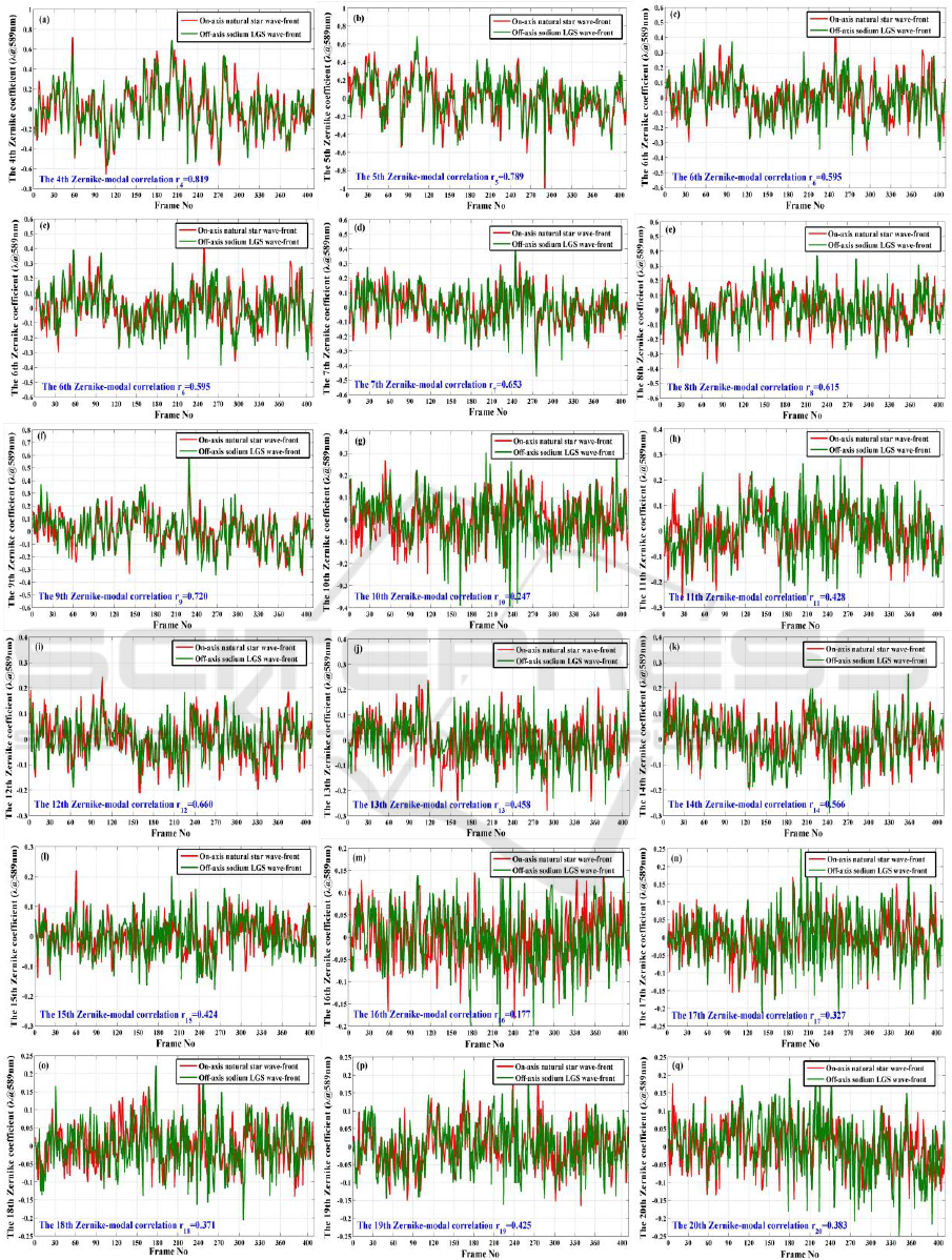
Figure 6: The typical experimental result of the first 20th Zernike-modal correlations of the recovered wave-front distortion
between the on-axis natural star and the off-axis sodium LGS with 10” angular offsets.
Experimental Measurement of Angular Anisoplanatism for Sodium Laser Guide Star: Synchronized Range Gating Realization
107
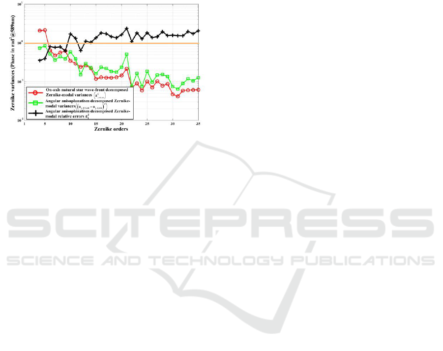
axis sodium LGS, respectively (e.g., the average of
the Zernike-modal correlation <r
j
>=0.70 for j=4~9).
Increasing the Zernike-modal order j means
deteriorating correlation r
j
, the average of the
Zernike-modal correlation <r
j
>=0.46 for j=10~15,
but the average of the Zernike-modal correlation
<r
j
>=0.33 for j=16~20.
Figure 7: The typical experimental result of the angular
anisoplanatism decomposed Zernike-modal relative errors
for the off-axis sodium LGS with 10” angular offsets (Luo
et al., 2018).
The corresponding angular anisoplanatism
decomposed Zernike-modal relative errors for the
off-axis sodium LGS are calculated and illustrated in
Figure 7 (Luo et al., 2018). Resulting from improper
turbulent atmosphere probing with the off-axis
sodium LGS as reference on the outside of the
optical path from the natural star to the telescope
aperture, obvious de-correlations occur between the
majority of Zernike modes of the two types of wave-
front distortions from the on-axis natural star and the
off-axis sodium LGS, and the corresponding angular
anisoplanatism decomposed Zernike-modal relative
errors are bigger than one. This phenomenon is
basically consistent with our previous numerical
simulation work (Luo et al., 2015).
5 CONCLUSIONS
By means of the structural design of the range gating
mechanism accompanied with the synchronized
timing design of the sodium LGS excitation and
collection, the synchronized return-light spot arrays
through turbulent atmosphere from the science
object and the excited sodium LGS with certain
angular offsets can be collected by using our
developed HS wave-front sensor, which provides a
convenient way to experimental measurement of the
angular anisoplanatism for LGS. Further
investigation in this area will be carried out in the
future.
ACKNOWLEDGEMENTS
This work has been supported by the Young
Scientists Fund of the National Natural Science
Foundation of China (Grant No. 61505215).
REFERENCES
Luo, X., Li, X.Y., Hu, S.J., Huang, K., Wang, X.Y., 2018,
Experimental investigation of angular anisoplanatism
for sodium beacon. Acta Physica Sinica, 67 (9),
099501. (In Chinese)
Luo, X., Li, X.Y., Shao, L., Hu, S.J., Huang, K., 2015.
Investigation of anisoplanatic effect in adaptive optics
for atmospheric turbulence correction. In Proceedings
of SPIE, the 20th International Symposium on High-
Power Laser Systems and Applications. SPIE Press.
Foy, R., Labeyrie, A., 1985, Feasibility of adaptive
telescope with laser probe. Astronomy and
Astrophysics, 152 (2), L29-L31.
Fugate, R.Q., Fried, D.L., Ameer, G.A., Boeke, B.R.,
Browne, S.L., Roberts, P.H., Ruane, R.E., Tyler, G.A.,
Wopat, L.M., 1991, Measurement of atmospheric
wavefront distortion using scattered light from a laser
guide star. Nature, 353 (6340), 144-146.
Humphreys, R.A., Primmerman, C.A., Bradley, L.C.,
Herrmann, J., 1991, Atmospheric-turbulence
measurements using synthetic beacon in the
mesospheric sodium layer. Optics Letters, 16 (18),
1367-1369.
Fugate, R.Q., Ellerbroek, B.L., Higgins, C.H., Jelonek, M.
K., Lange, W.J., Slavin, A.C., Wild, W.J., Winker,
D.M., Wynia, J.M., Spinhirne, J.M., Boeke, B.R.,
Ruane, R.E., Moroney, J.F., Oliker, M.D., Swindle,
D.W., Cleis, R.A., 1994, Two generations of laser-
guide-star adaptive-optics experiments at the Starfire
Optical Range. Journal of the Optical Society of
America A, 11 (1), 310-324.
Bonaccini, D., Hackenberg, W., Avila, G., 1998. Laser
guide star facility for the ESO VLT. In Proceedings of
SPIE, Adaptive Optical System Technologies. SPIE
Press.
Joyce, R., Boyer, C., Daggert, L., Ellerbroek, B., Hileman,
E., Hunten, M., Liang, M., 2006. The laser guide star
facility for the Thirty Meter Telescope. In Proceedings
of SPIE, Advances in Adaptive Optics II. SPIE Press.
Molodij, G., Rousset, G., 1997, Angular correlation of
Zernike polynomials for a laser guide star in adaptive
optics. Journal of the Optical Society of America A, 14
(8), 1949-1966.
Sasiela, R.J., 2007. Electromagnetic wave propagation in
turbulence: evaluation and application of Mellin
transforms, SPIE Press. Washington, 2
nd
edition.
PHOTOPTICS 2019 - 7th International Conference on Photonics, Optics and Laser Technology
108

Van Dam, M.A., Sasiela, R.J., Bouchez, A.H., Mignant,
D.L., Campbell, R.D., Chin, J.C.Y., Hartman, S.K.,
Johansson, E.M., Lafon, R.E., Stomski, P.J., Summers,
D.M., Wizinowich, P.L., 2006. Angular
anisoplanatism in laser guide star adaptive optics. In
Proceedings of SPIE, Advances in Adaptive Optics II.
SPIE Press.
Chen, T.J., Zhou, W.C., Wang, F., Huang, D.Q., Lu, Y.H.,
Zhang, J.Z., 2015, Experimental research on focusing
anisoplanatism of sodium guide star via synchronous
pulse detection. Acta Physica Sinica, 64 (13), 134207.
(In Chinese)
Noll, R.J., 1976, Zernike polynomials and atmospheric
turbulence. Journal of the Optical Society of America,
66 (3), 207-211.
Experimental Measurement of Angular Anisoplanatism for Sodium Laser Guide Star: Synchronized Range Gating Realization
109
