
Relative Pose Improvement of Sphere based RGB-D Calibration
David J. T. Boas
1,2
, Sergii Poltaretskyi
2
, Jean-Yves Ramel
1
, Jean Chaoui
2
, Julien Berhouet
1,3
and Mohamed Slimane
1
1
Laboratoire d’Informatique Fondamentale Appliquée de Tours(LIFAT), Université François Rabelais, 37200 Tours, France
2
IMASCAP, 29280, Plouzané, France
3
Service Orthopédie 1, Centre Hospitalier Universitaire de Tours, Avenue de la République, 37044 Tours Cedex 09, France
Keywords:
Computer Vision, RGB-Depth Camera, Camera Calibration, Spherical Object.
Abstract:
RGB-Depth calibration refers to the estimation of both RGB and Depth camera parameters, as well as their
relative pose. This step is critical to align streams correctly. However, in the literature there is still no general
method for accurate RGB-D calibration. Recently, promising methods proposed to use spheres to perform the
calibration, the centers of these objects being well distinguishable by both cameras. This paper proposes a new
minimization function which constrains spheres centers positions by requiring the knowledge of sphere radius,
and a previously calibrated RGB camera. We show the limits of previous approaches and their correction
with the proposed method. Results demonstrate an improvement in relative pose estimation compared to the
original method on the selected datasets.
1 INTRODUCTION
The recognition of a real scene to allow digital inte-
raction is one major problem in computer vision ap-
plications. A key component of many scene under-
standing approaches is the determination of 3D coor-
dinates of objects of interest. The recent increase in
the availability of low cost Depth cameras offers new
approaches to this problem. The combination of a
Depth sensor with an RGB camera provides broade-
ned scene information, and is referred to as an RGB-D
device.
To operate accurately, it is critical to know the ca-
libration parameters of the sensor pair, i.e. the intrin-
sic parameters of both cameras, and the rigid transfor-
mation between the optic centers of the two cameras.
However, the quality of manufacturer RGB-D calibra-
tion differs for each camera model, and is inadequate
for high precision applications. The calibration of an
RGB-D camera presents new challenges against the
calibration of an RGB camera:
1. Popular color feature points, such as the corners of
a checkerboard, are not visible by a Depth camera.
2. Depth maps given by Depth cameras are usually
noisy, with noise increasing quadratically with the
distance.
3. Depth measurements are unreliable on the border
of objects.
Recent RGB-D calibration approaches still suffer
from a few pixels shift. Moreover, the relative pose
estimation between the two cameras may be highly
imprecise. These approximations come from inaccu-
racies between RGB and Depth matching points. The
origin of these errors can be explained by the obser-
vation that Depth cameras are subject to several types
of noise. The noise originates from the shapes, posi-
tions or materials of the objects present in the scene.
Their effect typically increases quadratically with the
distance. Some recent publications try to address this
issue (Herrera C. et al., 2012; Basso et al., 2018). To
the best of our knowledge, no sphere based calibration
method proposed to handle it.
This paper is built upon a previous work which
proposed to use spheres for close distance RGB-D
calibration (Staranowicz et al., 2014). The appro-
ach requires both a calibrated RGB camera and an
uncalibrated Depth camera to observe a spherical ob-
ject. This approach relies heavily on 2D data to per-
form calibration. However, the loss of 3D information
eventually leads to relative pose estimation errors.
Alternatively, several sphere based calibration
methods are based on the principle of precisely deter-
mining the center of a sphere (Schnieders and Wong,
2013; Sun et al., 2016). It has been proposed to
Boas, D., Poltaretskyi, S., Ramel, J., Chaoui, J., Berhouet, J. and Slimane, M.
Relative Pose Improvement of Sphere based RGB-D Calibration.
DOI: 10.5220/0007309700910098
In Proceedings of the 14th International Joint Conference on Computer Vision, Imaging and Computer Graphics Theory and Applications (VISIGRAPP 2019), pages 91-98
ISBN: 978-989-758-354-4
Copyright
c
2019 by SCITEPRESS – Science and Technology Publications, Lda. All rights reserved
91

use 3D sphere’s centers for camera network relative
pose estimation for either Depth cameras (Minghao
Ruan and Huber, 2014), or RGB cameras (Guan et al.,
2015). This approach has yet to be applied to RGB-D
calibration.
Based on these ideas, we propose to perform the
calibration in 3D, using the estimated spheres centers
of both RGB and the Depth cameras to perform the
calibration. We introduce an alternative non-linear
optimization function, which only requires supple-
mentary knowledge of the sphere radius. An evalu-
ation of our approach upon synthetically generated
data, and real data (Boas et al., 2018) shows this in-
formation can be used to improve relative pose esti-
mation in RGB-D calibration.
In this paper, we focus on the problem of determi-
ning the Depth intrinsic parameters, and the extrinsic
parameters between the RGB and the Depth camera.
We intentionally omit any determination and refine-
ment of the RGB intrinsic parameters, as we consider
this step previously performed.
This paper is structured as follows. Section 2
surveys recent works related to RGB-D calibration.
Section 3 summarizes the initial approach with our
contribution. In Section 4, experimental data are pre-
sented. Finally, Section 5 and 6 outline the signifi-
cance of our contribution.
1.1 Problem Formulation
To align both RGB and Depth channels, it is necessary
to determine the intrinsic parameters of both cameras.
These parameters are commonly represented with a
pinhole camera model, which models the image for-
mation process by expressing the focal distance and
the center of the image (also known as the principal
point) into a 3x3 matrix.
The intrinsic parameters K of the two cameras are
noted as
R
K and
D
K, where {R } refers to the RGB
camera and {D} to the Depth camera; with ( f
u
, f
v
)
the focal length and (u
0
,v
0
) the principal point. The
two channels alignment is then carried out by a rigid
transformation (R|t), known as the extrinsic parame-
ters. This transformation is composed of a 3x3 rota-
tion matrix R and a 3x1 translation vector t.
2 RELATED WORKS
RGB-D calibration methods are mainly supervised,
i.e. use objects with known geometric properties to
perform the calibration. The idea is to find matching
points between both cameras to determine the calibra-
tion parameters.
Checkerboard Based Calibration. Similarly to
RGB calibration approaches, a commonly encounte-
red object in RGB-D calibration is a checkerboard.
The matching points are the checkerboard’s corners.
However, on a Depth map, the corners of a chec-
kerboard are not visible, and its border is inaccurate,
which negatively influences the results. Some remar-
kable approaches were proposed (Zhang and Zhang,
2014; Mikhelson et al., 2014). They, however, requi-
red either the user intervention to select points, or pre-
vious intrinsic camera calibration, making these ap-
proaches unpractical.
Approaches using checkerboard can rely on Infra-
red images, usually available from a Depth camera,
to perform the RGB-D calibration (Herrera C. et al.,
2012; Darwish et al., 2017). They propose to use
disparity images, built from the RGB and IR images.
However, these methods are often restricted to Struc-
tured Light Depth cameras, and the distortion obser-
ved between the IR and the Depth images has to be
modeled. An alternative method (Basso et al., 2018)
proposes the use of two Depth correction maps. Ho-
wever, this approach requires significant setup, as the
checkerboard must be placed on a plane at various dis-
tances, making it less pratical.
Sphere Based Calibration. Another object com-
monly used in camera calibration is the sphere. Its ad-
vantage in RGB-D calibration lies in its distinguisha-
bility by both cameras, and its full visibility regardless
of the point of view. A method for both intrinsic and
extrinsic calibration (Staranowicz et al., 2014) propo-
ses to use a sphere with unknown geometric proper-
ties, with their centers as matching points. They cor-
rect the error introduced by shifted ellipses centers,
and minimize the distance between the ellipse obser-
ved by the RGB camera and the projected sphere fit-
ted by the Depth camera. Others approaches (Shen
et al., 2014; Su et al., 2018), focus on camera net-
work extrinsic parameters estimation, and mainly use
data from the Depth camera.
3 PROPOSED METHOD
3.1 Original Method Description
Our work is based on the Staranowicz et al. method
(Staranowicz et al., 2014), where N spheres are pre-
sented in front of the RGB-D camera, as shown on Fi-
gure 1. A sphere is observed as a points cloud for the
Depth camera, and as an ellipse for the RGB camera.
The ellipse originates from the sphere projection onto
the camera plane, which can be assimilated to a conic
VISAPP 2019 - 14th International Conference on Computer Vision Theory and Applications
92

3D
2D
(R|t)
D
C
R
C
Camera
plane
Optic
center
D
O
s
p
j
e
r
R
O
e
{D} {R }
D
o
s
D
K
R
K
Figure 1: Overview of the RGB-D calibration scene. The
sphere is seen as an ellipse
R
C with center
R
O
e
for the
RGB camera {R }. The sphere is seen as a points cloud p
j
,
with center
D
O
s
for the Depth camera {D}. This center
is projected onto the Depth camera plane as
D
o
s
. The two
optic centers are linked by the rigid transform (R|t). The
reprojection error e
r
is the Euclidean distance between the
ellipse center
R
O
e
and the projected ellipse center of
D
C.
section. The method is composed of two phases: an
initialization and a non-linear optimization.
The initialization phase uses a variant of the Di-
rect Linear Transformation (DLT) (Hartley and Zis-
serman, 2004) to determine a first estimate of the
Depth camera intrinsic parameters
D
b
K, as well as
the extrinsic parameters (
c
R|t). Given a set of at le-
ast six 2D to 3D points matches (projected on the
plane Z defined by z = 1), the DLT algorithm de-
fines a homogeneous system whose resolution gives
the calibration parameters. The matching points are
the RGB ellipses centers
R
O
e
i
, and the Depth sp-
heres centers
D
O
s
i
:= (x
i
,y
i
,z
i
)
T
projected on Z as
D
o
s
i
:=
D
(u
i
,v
i
,1)
T
(Equation 1).
D
O
s
i
= z
i
D
K
−1D
o
s
i
(1)
These parameters are then refined by minimizing
a combination of the objective functions L
1
(Equa-
tion 3) and L
2
(Equation 4). Function L
1
expresses
the squared reprojection error e
r
. The reprojection er-
ror is defined as the Euclidean distance between RGB
ellipses centers
R
O
e
i
and the estimated ones from the
projection of the Depth spheres centers
D
O
s
i
onto the
RGB camera plane. It is represented by Equation 2
where
R
z
i
is the (z) parameter of the sphere center
expressed in the RGB camera coordinate system.
e
r
i
= ||
R
O
e
i
−
1
R
z
i
R
K(R
D
O
s
i
+ t)|| (2)
L
1
=
1
2N
N
∑
i=1
||e
r
i
||
2
(3)
Function L
2
expresses the Frobenius distance be-
tween the RGB and the Depth conic sections, i.e. the
ellipses. These conic sections are represented by the
3x3 matrices
R
C and
D
C; with C
−1
the dual conic
of C (in the case of an ellipse). The Depth conic
section
D
C is estimated from the projection of the fit-
ted Depth sphere
D
O
s
i
onto the RGB camera plane
(Staranowicz et al., 2014). f (
D
O
s
i
))
2
is a quadra-
tic function of the Depth sphere center to represent
the loss of accuracy of Depth cameras increasing with
distance.
L
2
=
1
2N
N
∑
i=1
1
( f (
D
O
s
i
))
2
||
R
C
−1
i
−
D
C
−1
i
||
2
F
(4)
The combination of both function gives the objective
function to minimize (Equation 5) :
min
D
K,R,t
ρ
1
L
1
+ ρ
2
L
2
(5)
Specific Aspects. Unlike the original method, the el-
lipses centers are not corrected, as the displacement
effect is minimal at close distance. Moreover, their
ellipse center correction proposition is valid only if
the ellipse is oriented towards the principal point of
the image, which is not the case of a standard ellipse
fitting algorithm. As for Equation 4, we defined f
2
as the squared Depth sphere center distance with re-
spect to the camera. The weight ρ
1
and ρ
2
are chosen
similarly.
3.2 Proposed Objective Function
In order to reduce noise impact observed on Equa-
tion 5, we propose a new minimization function L
3
(Equation 6) to better constrain the calibration para-
meters. Function L
3
represents the mean of the squa-
red Euclidean distances between the spheres centers
R
O
s
i
estimated from the RGB camera, and the sphe-
res centers
D
O
s
i
estimated from the Depth camera.
The RGB spheres positions
R
O
s
i
are retrieved from
the RGB ellipses
R
C
i
, the sphere radius R, as shown
in Section 3.3.
L
3
=
1
2N
N
∑
i=1
||
R
O
s
i
−(R
D
O
s
i
+ t)||
2
(6)
The function L
3
can be seen as the 3D equivalent
of the function L
2
in the case of fixed sphere radius.
However, it does not express well the reprojection er-
ror observed on the RGB camera. We thus define a
new objective function as the linear combination of
L
1
and L
3
(Equation 7).
min
D
K,R,t
ρ
1
L
1
+ ρ
3
L
3
(7)
Figure 2 proposes an overview of this method,
with our contribution.
Relative Pose Improvement of Sphere based RGB-D Calibration
93
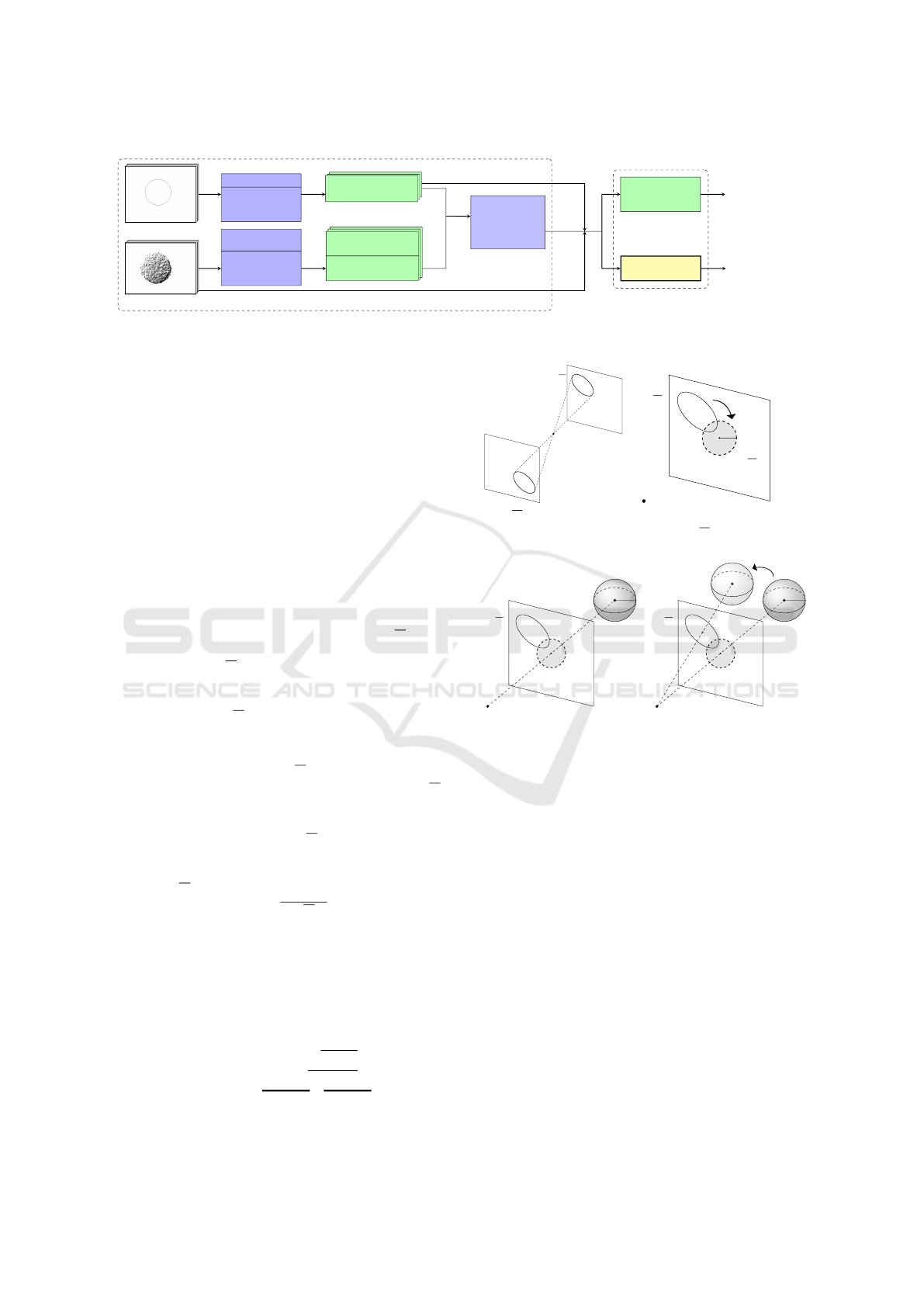
RGB Image i
Depth Point Cloud i
Ellipse Detection
RANSAC-based
Least square
Ellipse Fitting
Sphere’s Points
Detection
Iterative
Least square
Sphere Fitting
Ellipse
R
C
i
R
O
e
i
:=
R
(u
i
,v
i
,1)
T
Sphere Centers
D
O
s
i
:
= (x
i
,y
i
,z
i
)
T
Projected Centers
D
o
s
i
:
=
D
(u
i
,v
i
,1)
T
At least 6 couples
(
R
O
e
i
, z
i
.
D
o
s
i
) +
R
K
Selection &
Calibration
Parameters
Estimation
DLT
Initialization
D
b
K
[
(R|t)
Staranowicz
et al. function
ρ
1
L
1
+ ρ
2
L
2
Our function
ρ
1
L
1
+ ρ
3
L
3
D
b
K
1
,
[
(R|t)
1
D
b
K
2
,
[
(R|t)
2
R
C
Non Linear Optimization
Figure 2: Simplified pipeline of the Staranowicz et al. (Staranowicz et al., 2014) method, with our proposed objective function
(in yellow).
3.3 Retrieving a Sphere Center From an
RGB Ellipse
To define Equation 7, it is necessary to determine the
3D Spheres centers
R
O
s
i
with respect to the RGB ca-
mera. To retrieve the 3D sphere center
R
O
s
from a
2D view, the knowledge of the conic shape
R
C, the
intrinsic parameters
R
K and the 3D sphere radius R
are necessary. We propose to use a linear approach
(Schnieders and Wong, 2013), which gives a perfect
estimate given noise free data. This method is com-
posed of four main steps:
Step 1 (3a) : The effect of
R
K on the conic
R
C is
withdrawn, by normalizing it with
R
K
T
. The conic
R
C is transformed as the normalized conic
R
C :
R
C =
R
K
T R
C
R
K (8)
Step 2 (3b) : A rotation
R
U
T
is performed to trans-
form the ellipse
R
C as a circle
R
D. This circle is
centered at the origin (0,0) of the camera plane. The
rotation
R
U
T
is found by applying a Singular Value
Decomposition (SVD) on
R
C.
R
U is the orthogo-
nal matrix whose columns are the eigenvectors of
R
C.
Thus, the circle
R
D is defined as following:
R
D =
R
U
T R
C
R
U (9)
The circle matrix
R
D is normalized by its first ele-
ment as
R
D =
R
D/
R
D
00
. The radius r of the circle
can be computed as r =
p
−
R
D
22
.
Step 3 (3c) : The sphere center O
s
is retrieved by
using the relationship between r and the radius R of
the sphere, as expressed in Equation 10.
Step 4 (3d) : The rotation
R
U is applied to reverse the
rotation
R
U
T
, and express the sphere with respect to
the ellipse as
R
O
s
.
R
O
s
=
R
U[0 0 R(
√
1 + r
2
r
)]
T
| {z }
O
s
(10)
R
C
R
C
(a)
R
C is the conic
R
C
without the effect of
R
K.
R
C
R
U
T
r
R
D =
R
D
(b)
R
U
T
is applied to express
the conic
R
C as a circle
R
D.
R
C
R
D
R
O
s
(c) The circle
R
D is back
projected as a sphere.
R
C
R
U
R
D
R
R
O
s
(d)
R
U is applied to retrieve
the sphere center
R
O
s
.
Figure 3: Overview of the steps in order to back project an
ellipse C into a sphere (Schnieders and Wong, 2013).
4 EXPERIMENTS
We evaluate the accuracy of the ellipse back pro-
jection approach exposed in Section 3.3 with synt-
hetically generated data, and assess its suitability for
RGB-D calibration. We then evaluate our proposi-
tion, derived from Equation 7 to Staranowicz et al.
method. on several synthetic and real datasets (Boas
et al., 2018). It is important to note that in order to
have a fairer comparison, we use the sphere radius
knowledge for both approaches.
4.1 Ellipse Back Projection Accuracy
The ellipse back projection method (Schnieders and
Wong, 2013) provides the real sphere 3D position
VISAPP 2019 - 14th International Conference on Computer Vision Theory and Applications
94
with noise free data. The method accuracy depends
on the estimation of the ellipse
R
C, the estimation of
the intrinsic parameters of the RGB camera
R
K, on
the sphere position O
s
, and on the estimated sphere
radius R. In a calibration setup, the sphere radius can
be considered known with high accuracy. However,
noise is typically observed on the estimations of
R
C
and
R
K. To further evaluate the method validity in a
calibration context, synthetic scenes with known pa-
rameters were created.
Scene Description. A reference sphere of radius R =
40 mm is placed at O
s
= (100,100,700)
T
. The sphere
is projected onto the camera plane with known intrin-
sic parameters
R
K as f
u
= f
v
= 1000, and (u
0
,v
0
) =
(640,480). The ellipse back projection method is
then applied to estimate the sphere’s center. During
the experiments, a zero-mean Gaussian noise N is
applied on either the ellipse’s points or the intrinsic
parameters. To obtain a reliable metric, each experi-
ments were performed 1000 times, and use the Mean
Absolute Error (MAE) of the sphere’s center parame-
ters.
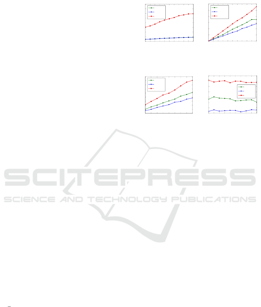
Analysis. The Figure 4a shows the results of the el-
lipse back projection method against noise applied on
the RGB frame. This kind of noise originates from
blur in the image and inaccuracies in ellipse fitting. To
replicate this behavior, a zero-mean Gaussian noise
N (0,σ
R
) is applied on every pixel belonging to the
ellipse. A Least-Square ellipse fitting algorithm is
used to fit the new ellipse. On Figure 4b, the noise
applied on the intrinsic parameters is observed. The
noise observed on
R
K originates from inaccuracies
during the RGB calibration method. A zero-mean
Gaussian noise N (0, σ
K
) is applied on all calibration
parameters ( f
u
, f
v
,u
0
,v
0
). A study on current RGB
calibration methods (Wong et al., 2011; Liu et al.,
2017) allows us to estimate σ
K
between 1‰ and 5‰
of the real calibration parameters values.
On Figure 4c, the sphere is placed along the vec-
tor between the origin and the reference sphere center
O
s
, but with varying distance. The intrinsic Gaus-
sian noise standard deviation is fixed at σ
K
= 2‰.
On Figure 4d, the effect of rotation is studied. A
rotation is performed along the normal of the ca-
mera plane (i.e. the (z) axis) to modify the sp-
here’s center position. The center position goes from
(
√
2∗100, 0, 700)
T
(0 deg.) to the initial reference sp-
here center (100,100,700)
T
(45 deg.). The intrinsic
Gaussian noise σ
K
is also applied.
Figure 4 shows that the back projection method is
sensible to noisy ellipse detection and inaccurate in-
trinsic parameter estimation. In all cases, the error
is mostly on the (z) parameter estimation, (x, y) pa-
rameters estimation being more accurate. This error
0.0 0.1 0.2 0.3 0.4 0.5 0.6 0.7 0.8 0.9 1.0
Noise σ
R
applied on the Ellipse (px)
0.0
0.2
0.4
0.6
0.8
1.0
1.2
1.4
1.6
Spheres centers parameters MAE (mm)
|
b
x − x|
|
b
y − y|
|
b
z − z|
(a) MAE against Gaussian
noise N (0, σ
R
) applied on
the ellipse points.
0.0 0.2 0.4 0.6 0.8 1.0 1.2 1.4 1.6 1.8 2.0
Noise applied on
R
K (‰px)
0.0
0.2
0.4
0.6
0.8
1.0
1.2
Spheres centers parameters MAE (mm)
|
b
x − x|
|
b
y − y|
|
b
z − z|
(b) MAE against Gaussian
noise N (0,σ
K
) applied on
R
K.
400 500 600 700 800 900 1000 1100 1200
Sphere Distance (mm)
0.2
0.4
0.6
0.8
1.0
1.2
1.4
1.6
1.8
2.0
Spheres centers parameters MAE (mm)
|
b
x −x|
|
b
y − y|
|
b
z − z|
(c) MAE with increasing dis-
tance and Gaussian noise
N (0, σ
K
= 2h).
0 5 10 15 20 25 30 35 40 45
Axis Rotation (deg.)
0.5
0.6
0.7
0.8
0.9
1.0
1.1
1.2
Spheres centers parameters MAE (mm)
|
b
x − x|
|
b
y − y|
|
b
z − z|
(d) MAE with increasing
angle and Gaussian noise
N (0, σ
K
= 2h).
Figure 4: Ellipse back projection
R
C into a sphere O
s
mean
absolute error (MAE) for several parameters.
is amplified by the distance between the sphere and
the camera, but is robust to angle variations. At most,
the back projection error is at 2 mm. Nonetheless,
the suitability of this approach for RGB-D calibration
will be demonstrated below.
It is important to note that this approach requires
the sphere radius to be known with high accuracy (no
more than a few % of error). However, this is not a
problem in the case of a 3D printed sphere (with sub-
millimeter printing accuracy).
4.2 Synthetic Scene Setup
The synthetically generated sequences are designed to
evaluate the robustness of both methods against vari-
ous measurements noise (see Figure 5).
Data Generation. An RGB-D camera couple with
known extrinsic parameters is placed in a 3D scene.
The spheres positions and radius, the transformation
(R|t) and the intrinsic parameters
R
K and
D
K are
known and fixed.
The RGB camera is placed 30 mm above the
Depth camera, with no rotation. The rotation vector is
defined as θ = (θ
x
,θ
y
,θ
z
)
T
. θ is the representation of
R as Euler angles in degrees. The translation vector
is defined as t = (t
x
,t
y
,t
z
)
T
in mm.
As proposed by Staranowicz et al. (Staranowicz
et al., 2014), twenty 3D points
D
O
s
i
,i ∈ [1,20] are
randomly generated at the intersection of the field of
view of the two cameras. For each sphere center
D
O
s
i
,
Relative Pose Improvement of Sphere based RGB-D Calibration
95
Reference Scene :
R
K;
D
K;(R|t);
20 Spheres (O
s
,R)
Apply Noise
Fixed RGB Noise : σ
R
Fixed Intrinsic Noise : f (
R
K)
Depth Noise : σ
D
Noise σ
D
= 0.8
Noise σ
D
= 0.4
Noise σ
D
= 4.0
.
.
. σ
D
∈ [0, 4.0]
Evaluation i
Evaluation 1
Evaluation 100
.
.
. i ∈ [1, 100]
Figure 5: Overview of synthetic data generation.
100 3D points p
i j
, j ∈[1,100] are randomly generated
on the periphery of half of the sphere by using the
parametric equation of a sphere. The input data of
the algorithm is generated from these twenty sets of a
hundred points. These spheres are projected onto the
RGB camera plane to obtain the associated ellipses.
Associated Depth maps are generated by projecting
the points p
i j
onto the Depth camera plane.
Noise Application. The noise on the RGB camera
is modeled with a zero-mean Gaussian noise on the
RGB frames similarly to Section 4.1, with σ
R
= 0.6.
A fixed Intrinsic noise on
R
K is applied by multi-
plying each calibration parameters by the value η =
1 + 2‰ in order to have a similar noise on each se-
quence. Its value is determined similarly as σ
K
in
Section 3.3. Depth camera noise is modeled by a shift
on the sphere points p
i j
, and thus
D
O
s
i
, to characte-
rize any kind of error. This noise is labeled σ
D
, and
is our variable of interest. All tests were evaluated a
hundred times.
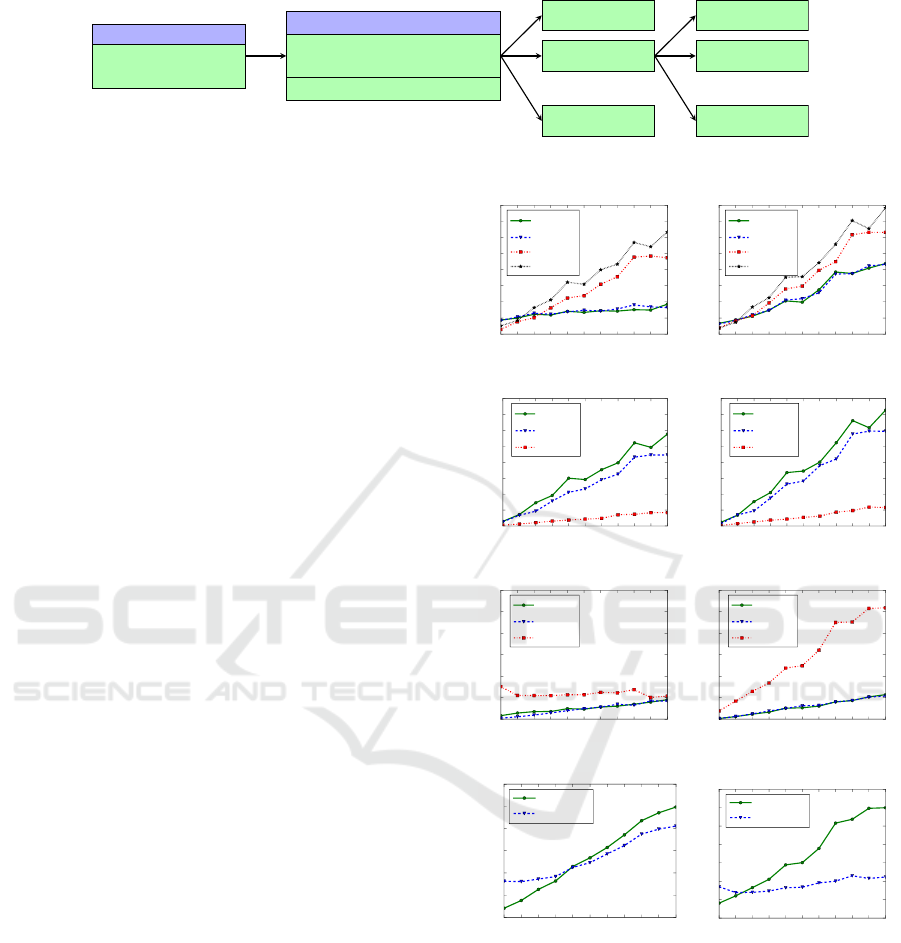
4.3 Synthetic Data Comparison
Figure 6 summarizes the results after evaluating both
methods on synthetically generated data. Increasing
Depth noise σ
D
is applied on Depth data. The Mean
Absolute Error (MAE) is used to compare every pa-
rameters involved in the RGB-D calibration, as well
as the 2D (e
r
) and 3D reprojection error (E
r
). The 3D
reprojection error (Equation 11) is the Euclidean dis-
tance between the real spheres centers and the ones
estimated from Section 3.3 approach. This metric
more accurately accounts for Depth evaluation errors,
as the 2D reprojection error tends to hide depth dis-
placements (in the case both cameras are close).
E
r
i
= ||
R
O
s
i
−(R
D
O
s
i
+ t)|| (11)
On Figure 6, better results are observed for our
proposition (Equation 7), especially for parameters
involving distances, as this approach allows to recover
depth information from the RGB camera. This is par-
ticularly visible on Figures 6a and 6e, with the focal
estimation f
u
, f
v
and the translation along the depth
axis t
z
. Both reprojection errors are higher on error
free Depth data as our proposition is more sensible to
RGB noise than the Staranowicz et al. method.
0.0 0.4 0.8 1.2 1.6 2.0 2.4 2.8 3.2 3.6 4.0
Noise σ
D
(mm)
0
2
4
6
8
10
12
14
16
Intrinsic parameters MAE (px)
Proposed Equation 7
|
b
f
u
− f
u
|
|
b
f
v
− f
v
|
|
b
u
0
− u
0
|
|
b
v
0
− v
0
|
(a)
0.0 0.4 0.8 1.2 1.6 2.0 2.4 2.8 3.2 3.6 4.0
Noise σ
D
(mm)
0
2
4
6
8
10
12
14
16
Intrinsic parameters MAE (px)
Staranowicz et al. Equation 2
|
b
f
u
− f
u
|
|
b
f
v
− f
v
|
|
b
u
0
− u
0
|
|
b
v
0
− v
0
|
(b)
0.0 0.4 0.8 1.2 1.6 2.0 2.4 2.8 3.2 3.6 4.0
Noise σ
D
(mm)
0.0
0.2
0.4
0.6
0.8
1.0
1.2
1.4
1.6
Rotation MAE (deg.)
Proposed Equation 7
|
b
θ
x
− θ
x
|
|
b
θ
y
− θ
y
|
|
b
θ
z
− θ
z
|
(c)
0.0 0.4 0.8 1.2 1.6 2.0 2.4 2.8 3.2 3.6 4.0
Noise σ
D
(mm)
0.0
0.2
0.4
0.6
0.8
1.0
1.2
1.4
1.6
Rotation MAE (deg.)
Staranowicz et al. Equation 2
|
b
θ
x
− θ
x
|
|
b
θ
y
− θ
y
|
|
b
θ
z
− θ
z
|
(d)
0.0 0.4 0.8 1.2 1.6 2.0 2.4 2.8 3.2 3.6 4.0
Noise σ
D
(mm)
0
2
4
6
8
10
12
Translation MAE (mm)
Proposed Equation 7
|
b
t
x
− t
x
|
|
b
t
y
− t
y
|
|
b
t
z
− t
z
|
(e)
0.0 0.4 0.8 1.2 1.6 2.0 2.4 2.8 3.2 3.6 4.0
Noise σ
D
(mm)
0
2
4
6
8
10
12
Translation MAE (mm)
Staranowicz et al. Equation 2
|
b
t
x
− t
x
|
|
b
t
y
− t
y
|
|
b
t
z
− t
z
|
(f)
0.0 0.4 0.8 1.2 1.6 2.0 2.4 2.8 3.2 3.6 4.0
Noise σ
D
(mm)
0.0
0.5
1.0
1.5
2.0
2.5
3.0
Mean 2D reprojection error (px)
2D Reprojection error
e
r
- Eq. 2
e
r
- Eq. 7
(g)
0.0 0.4 0.8 1.2 1.6 2.0 2.4 2.8 3.2 3.6 4.0
Noise σ
D
(mm)
0
2
4
6
8
10
12
14
Mean 3D reprojection error (mm)
3D Reprojection error
E
r
- Eq. 2
E
r
- Eq. 7
(h)
Figure 6: Simulation results of both approaches : (a) & (b)
- Mean absolute Intrinsic parameters errors with increasing
noise on Depth data. (c) & (d) - Mean absolute Translation
error. (e) & (f) - Mean absolute Rotation error. (g) & (h) -
2D and 3D Reprojection error.
The main improvement is particularly visible on
Figure 6h, with 3D reprojection error E
r
results im-
proving by many millimeters, something that is due
to the better estimated Depth intrinsic parameters and
relative pose between both cameras. The constraint
on sphere centers introduced by the ellipse back pro-
VISAPP 2019 - 14th International Conference on Computer Vision Theory and Applications
96

jection attenuates calibration parameters divergence
as σ
D
increases. It is interesting to note that E
r
clo-
sely follows the mean absolute translation errors on t
z
.
Obviously, the more accurate the RGB intrinsic para-
meters estimation, as well as the ellipse detection, the
better our results. Considering the ellipse back pro-
jection method introduced on average an error of 2
mm, an improvement of this approach should further
improve Equation 7 results.
4.4 Real Data Comparison
Both approaches are evaluated on a real dataset, com-
prising three sequences, each representing a different
scenario. For each of these sequences, RGB frames,
Depth points clouds, and manufacturer intrinsic para-
meters are available. The Random and Equidistant se-
quences have been taken with a separated RGB-D ca-
mera couple, where the Depth camera is placed above
the RGB camera. The Random sequence consists of
72 RGB-D frames couples of a randomly distributed
sphere’s position. The Equidistant sequence consists
of 27 RGB-D frames couples of a sphere positioned to
equidistantly cover the field of view of both cameras.
Both datasets use a Hololens (Microsoft, Redmond,
USA) front facing RGB camera and Picoflexx (PMD
Technologies, Siegen, Germany) Depth camera cou-
ple. The Double sequence has been taken with a Real-
sense SR300 (Intel, Santa Clara, USA), which allows
us to compare against the manufacturer given extrin-
sic parameters (R|t). This sequence consists of 20
RGB-D frames couples of a support with two sphe-
res. The spheres are painted in blue to ease the ellipse
detection step.
Data Extraction. Ellipse detection follows the next
approach. An initial estimate is obtained by color
thresholding. A Canny-edge algorithm is then per-
formed around the ellipse’s outline. The final ellipse
is determined by a RANSAC based Least-Square (in
the algebraic distance sense) ellipse-fitting method to
have a robust estimate. Points cloud segmentation is
performed by an internal algorithm. Finally, an Ite-
rative Least-Square sphere fitting using the Radius R
knowledge is performed to obtain
D
O
s
. This algo-
rithm minimize the difference between the radius R
and the Euclidean distance of the points with respect
to
D
O
s
using the centroid as the initial guess. The
sphere center is then projected back onto the Depth
camera plane using the manufacturer intrinsic para-
meters. All RGB-D frames couples are selected, as
long as their sphere fitting error (Root Mean Square
error of the points distance to the center) is below a
fixed threshold. These couples allows to build the ho-
mogeneous system according to the DLT algorithm.
The linear estimate is then refined by optimization,
using the Levenberg-Marquardt algorithm.
Calibration results are shown on Table 1. A re-
projection error improvement is visible for our propo-
sition. The resulting calibration parameters are, ho-
wever, quite different. The synthetic results suggest
that the estimated parameters associated with the new
approach are more accurate. Figure 7 gives a visua-
lization of the RGB-D alignment at different step of
the calibration. As expected by the synthetic results,
the visualization is similar for the Staranowicz et al.
and our method. However, the improvement is clearly
visible against the manufacturer provided calibration,
and the initialization phase.
5 DISCUSSION AND FUTURE
WORK
The results demonstrate that the initial method (Stara-
nowicz et al., 2014) is quite sensitive to noise, especi-
ally on depth sphere center
D
b
O
s
i
estimate. This does
not impact to a great extent the 2D reprojection error,
but ultimately leads to inaccurate translation
b
t
z
and fo-
cal ( f
u
, f
v
) estimates. We identify this translation er-
ror as one of the main drawbacks of the Staranowicz
et al. approach. Using the back projection of RGB el-
lipses into spheres allows for a more precise relative
pose estimation. We believe our approach allows to
use the advantages of both sensors.
In practice, it is possible to accurately detect an
ellipse on an RGB frame in a controlled calibration
scene. However, the sphere fitting on a points cloud
offers more challenges, because of the presence of
outliers and the depth distance error of the Depth ca-
mera, leading to a difference of several millimeters.
Our contribution allows to mitigate this aspect, by
making use of the RGB ellipses which can be esti-
mated with the knowledge of the sphere radius. Ho-
wever, our approach requires a highly accurate cali-
bration and ellipse detection.
Constraining the (z) axis is particularly important,
considering the noise increasing with the distance ty-
Table 1: 2D Reprojection error e
r
by applying both approaches on real datasets.
Metric \ Dataset Random Equidistant Double
Mean ± STD Stara. Our Stara. Our Stara. Our Manufacturer
e
r
(px) 2.25 ± 1.28 2.17 ± 1.10 2.49 ± 1.29 2.33 ± 1.05 7.03 ± 2.76 6.48 ± 2.82 28.8 ± 3.61
Relative Pose Improvement of Sphere based RGB-D Calibration
97
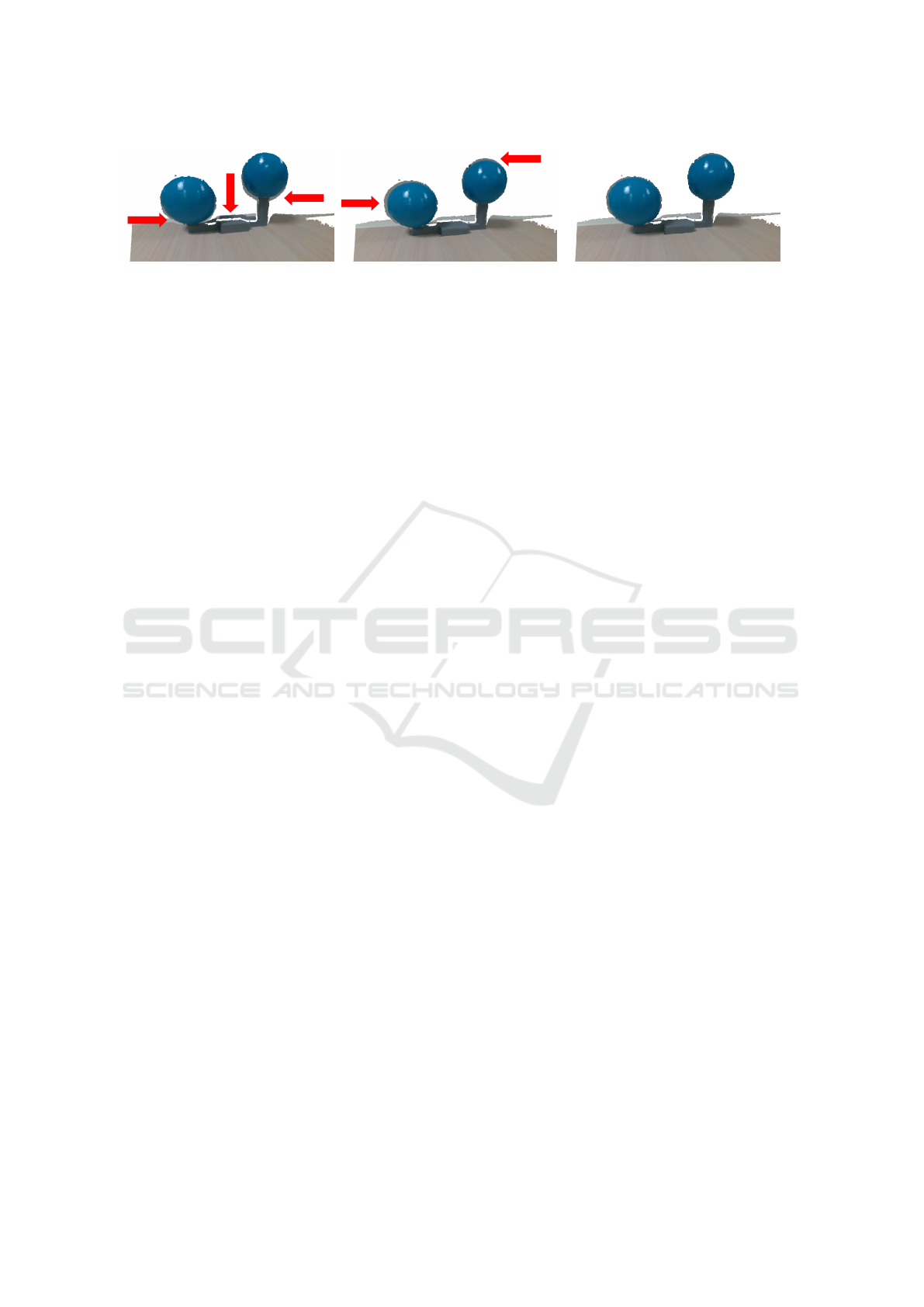
(a) Manufacturer calibration. (b) Initialization calibration. (c) Proposed minimization. Staranowicz
et al. minimization alignment is similar.
Figure 7: Alignment results on the Double dataset. Misalignments are highlighted in red.
pically observed by Depth cameras. These methods
are restricted to low range RGB-D calibration, as no
modelization of the Depth noise is proposed. In future
work, we seek to deal with the noise increasing with
the distance observed by Depth camera, and improve
the ellipse back projection accuracy.
6 CONCLUSION
This work demonstrates the sensitivity of the Starano-
wicz et al. method (Staranowicz et al., 2014) to noisy
measurements. We proposed a new minimization ob-
jective function to better constrain the relative transla-
tion and the intrinsic parameters of the Depth camera.
Multiple simulations with both synthetic data that re-
produces real conditions and real data were perfor-
med to determine and quantify the evolution of cali-
bration parameters. We showed that using the 3D cen-
ters of spheres, instead of their 2D projection allows
to improve the calibration parameters estimation, es-
pecially with high accuracy cameras and noisy Depth
data.
REFERENCES
Basso, F., Menegatti, E., and Pretto, A. (2018). Robust In-
trinsic and Extrinsic Calibration of RGB-D Cameras.
IEEE Transactions on Robotics, pages 01–18.
Boas, D. J. T., Ramel, J.-Y., Slimane, M., and Poltaretskyii,
S. (2018). Rgb-d sphere-based calibration dataset.
http://www.rfai.li.univ-tours.fr/tools-and-demos/.
Darwish, W., Tang, S., Li, W., and Chen, W. (2017). A New
Calibration Method for Commercial RGB-D Sensors.
Sensors, 17(6):1204.
Guan, J., Deboeverie, F., Slembrouck, M., van Haeren-
borgh, D., van Cauwelaert, D., Veelaert, P., and Phi-
lips, W. (2015). Extrinsic Calibration of Camera Net-
works Using a Sphere. Sensors, 15(8):18985–19005.
Hartley, R. and Zisserman, A. (2004). Multiple View Ge-
ometry in Computer Vision. Cambridge University
Press, ISBN: 0521540518, second edition.
Herrera C., D., Kannala, J., and Heikkila, J. (2012). Joint
Depth and Color Camera Calibration with Distortion
Correction. IEEE Transactions on Pattern Analysis
and Machine Intelligence, 34(10):2058–2064.
Liu, Z., Wu, Q., Wu, S., and Pan, X. (2017). Flexible and
accurate camera calibration using grid spherical ima-
ges. Optics Express, 25(13):15269–15285.
Mikhelson, I. V., Lee, P. G., Sahakian, A. V., Wu, Y., and
Katsaggelos, A. K. (2014). Automatic, fast, online
calibration between depth and color cameras. Journal
of Visual Communication and Image Representation,
25(1):218–226.
Minghao Ruan and Huber, D. (2014). Calibration of 3D
Sensors Using a Spherical Target. Proceedings of the
International Conference on 3D Vision, 01:187–193.
Schnieders, D. and Wong, K.-Y. K. (2013). Camera and
light calibration from reflections on a sphere. Compu-
ter Vision and Image Understanding, 117:1536–1547.
Shen, J., Xu, W., Luo, Y., Su, P.-C., and Cheung, S.-c. S.
(2014). Extrinsic calibration for wide-baseline RGB-
D camera network. IEEE 16th International Workshop
on Multimedia Signal Processing .
Staranowicz, A., Brown, G. R., Morbidi, F., and Mariottini,
G. L. (2014). Easy-to-Use and Accurate Calibration of
RGB-D Cameras from Spheres. In Image and Video
Technology, volume 8333, pages 265–278. Springer
Berlin Heidelberg.
Su, P.-C., Shen, J., Xu, W., Cheung, S.-C., and Luo, Y.
(2018). A Fast and Robust Extrinsic Calibration for
RGB-D Camera Networks. Sensors, 18(1):235.
Sun, J., He, H., and Zeng, D. (2016). Global Calibration of
Multiple Cameras Based on Sphere Targets. Sensors,
16(1):77.
Wong, K.-Y. K., Zhang, G., and Chen, Z. (2011). A Strati-
fied Approach for Camera Calibration Using Spheres.
IEEE Transactions on Image Processing, 20(2):305–
316.
Zhang, C. and Zhang, Z. (2014). Calibration Between
Depth and Color Sensors for Commodity Depth Ca-
meras. In Computer Vision and Machine Learning
with RGB-D Sensors, pages 47–64. Springer Interna-
tional Publishing.
VISAPP 2019 - 14th International Conference on Computer Vision Theory and Applications
98
