
Using fUML Combined with a DSML: An Implementation using
Papyrus UML/SysML Modeler
Maurice Theobald
1
and Jérémie Tatibouet
2
1
SAFRAN/SAFRAN Tech, Magny-Les-Hameaux, France
2
CEA, LIST, Laboratory of Model Driven Engineering for Embedded Systems, P.C. 174, Gif-sur-Yvette, 91191, France
Keywords: fUML, UML, SysML, Systems Architecture, DSML, Papyrus.
Abstract: The definition of standards is an efficient way to ensure a consensus on concepts and usages for a given
domain. Unified modeling language (UML) and System modeling language (SysML) are standards: UML
provides a large set of concepts enabling the specification of software-oriented systems meanwhile SysML
specializes UML for system engineering. Both languages have an accurate semantics, this is especially true
for UML which has a subset of objects (classes, composite structures, activities and state machines) that can
be executed. Executable UML is driven by the following standards: Foundational subset for executable UML
(fUML), precise semantics of UML composite structure (PSCS) and precise semantics of UML state machines
(PSSM). From the UML based standard contributor standpoint, there is a great temptation to conclude that
system architects can use these standards easily to model complex systems, and run simulations.
Unfortunately, in practice, this assumption hardly ever holds. Indeed, these standards are built to be generic
enough to apply for the largest possible set of systems. This implies that their scopes are wider than what is
required by a user to work in its domain. This problem is solved by using and specializing (if required) a
subset of these generic languages to match the needs. This paper shows how to reuse the power of UML,
SysML, fUML, PSCS and PSSM efficiently, with a customized version of Papyrus dedicated to system
architecture design.
1 INTRODUCTION
SysML (OMG, 2017a) provides many concepts that
can be reused to specify complex systems. To get the
benefits of this language (e.g., SysML), our company
has defined its profile on top of it. This profile is
implemented in a specialized version of Papyrus as a
pilot, to support the model-based systems engineering
(MBSE) (Cameron and Adsit, 2018) methodology
adopted by the group SAFRAN. Then it’s easier for a
system architect to use the profile and the methods
implemented in the tool, to model the architecture of
a system. However, while the language is well suited
to specify complex systems, it doesn’t provide the
capability to use models defined with this language
for simulation. This problem is mainly related to the
fact that SysML and its specialization have no formal
definition for their semantics. This assertion is true
for both SysML and its specialization at SAFRAN
since their semantics are defined in natural language.
Nevertheless, now, it became essential for SAFRAN
to validate the system designed based on its modeling
framework using simulation. To reach that goal,
models formalizing the system to be simulated must
be executable ones. Making models executables can
be performed in two ways: by formalizing the
execution semantics of the language used to specify
the model or by mapping the model to a language that
can be executed. At SAFRAN, the choice is to map
the models of a system into an equivalent model
conforming to an executable UML subset. The
rationale behind this choice is the following. First,
SAFRAN profile is based on the UML (OMG, 2017b)
and SysML (OMG, 2017a) standards, hence, if
semantics are defined for the models then they shall
be captured based on the standard semantics defined
for UML. Second, SAFRAN strongly advocates for
keeping the system specification models separated
from the model used to simulate. Indeed, at
SAFRAN, the system architect and the simulation
engineer are two contributors involved, to design the
system models. But only the simulation engineers
design the simulation model.
248
Theobald, M. and Tatibouet, J.
Using fUML Combined with a DSML: An Implementation using Papyrus UML/SysML Modeler.
DOI: 10.5220/0007310702480255
In Proceedings of the 7th International Conference on Model-Driven Engineering and Software Development (MODELSWARD 2019), pages 248-255
ISBN: 978-989-758-358-2
Copyright
c
2019 by SCITEPRESS – Science and Technology Publications, Lda. All rights reserved
The contribution reported in this paper is the
definition of the transformation rules to map a SysML
model to an executable model compliant with the
executable subset of UML. Beyond the
transformational aspects that remain classical, this
article shows how standards from the OMG,
specifying the semantics of subsets of UML could be
used to execute models.
The paper is organized as follows:
Section 2 presents the MBSE architecture framework
used in Safran, with a focus on the functional
architecture design. Section 3 presents an overview of
the intended semantics for functional models
specified within the architecture framework. Lastly,
section 4, presents how to generate a model used to
simulate from a functional specification. We used the
model of a toy quadcopter to illustrate our works.
2 OVERVIEWS OF THE MBSE
ARCHITECTURE
FRAMEWORK
The MBSE system architecture framework used in
Safran (Theobald et al., 2018) is made of three main
views:
Operational
Functional
Physical
A system architecture is designed and organized
according to these views.
The operational view defines the system as a black
box. Its main purpose is to capture how the system
interacts with its environment, collect and consolidate
the requirements specified by the stakeholders.
The physical view describes how the system
functions are implemented. It shows the interactions
between the system components, the subset of
components that are active according to the system
functional mode and the physical scenarios.
2.1 The Functional View
The functional point of view describes what the
system should do to provide the services required by
the stakeholders. Here the focus is on the
transformation process of functional flows inside the
system. These flows can be from many types: data,
mechanical, fluids, thermal, electrical, or
electromagnetic. During this transformation process,
the functional mode of the system is changing
depending on events; the system or its environment
generate these events. For functional mode, a set of
functions is enabled.
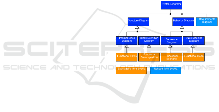
Four types of diagrams describe the functional
aspects:
The Functional mode diagram displays
the system functional state.
The Functional decomposition diagram
represents the system’s functional
breakdown structure. Here, the highest-
level functions are more abstract than the
lower-level functions.
The Functional flow diagram shows how
the flows are transformed within the
system.
The Functional scenario diagram
describes the temporal relationships
between the executions of the functions.
Figure 1 shows these diagrams.
Figure 1: The set of diagrams used to model the functional
view.
In this document the focus is on simulations from
the functional architecture view. Section 3 presents
the supported semantics.
3 THE FUNCTIONAL
INTERACTIONS SEMANTICS
The functional interaction diagram shows the
relationships between the function’s inputs and
outputs. It describes how the flows are consumed or
transformed within the system. However, it doesn’t
show the sequence of execution: parallel, alternate
path, sequence.
Functions are run in the following way:
A function can start its execution when flows
are ready on a subset of its inputs; data don’t
need to be ready for all inputs at the same time.
Using fUML Combined with a DSML: An Implementation using Papyrus UML/SysML Modeler
249
Note: In section 4 we consider a pure dataflow
case where all inputs are required to start the
execution.
The order in which the flows are ready for the
inputs of a function is not relevant.
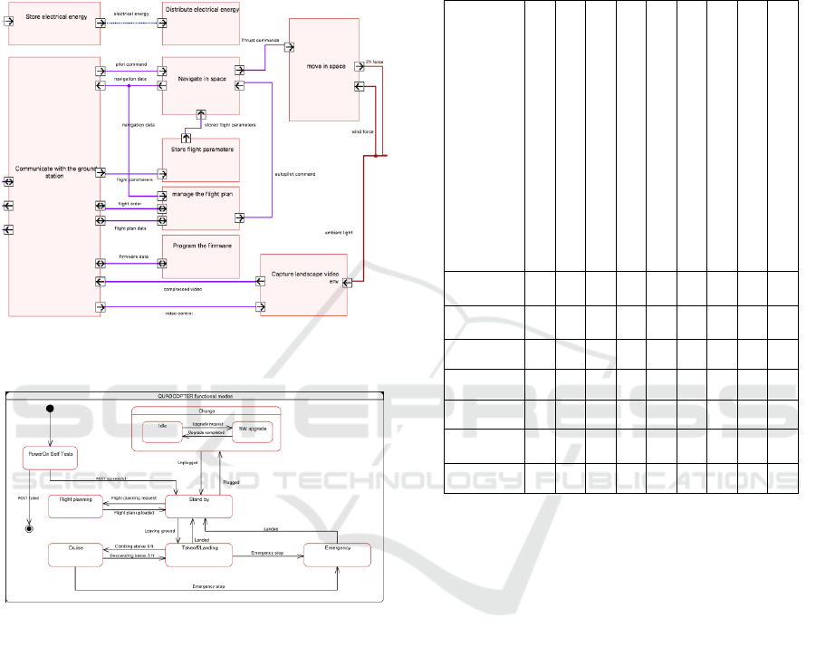
Let’s consider Figure 2, and Figure 3.
Figure 2: Abstract of functional flow diagram from the
quadcopter model.
Figure 3: The functional mode diagram of the quadcopter.
For each mode in Figure 3, a subset of functions from
Figure 2 is enabled.
For example, when the system is in Charge
mode, the function Program the firmware is
enabled, and can be executed. The other functions are
disabled, except the functions that manage the energy
of the drone. The reason is that functions Store
electrical energy and Distribute
electrical energy are transverse, and must be
active, as far as the system is powered on.
Table 1 shows the allocation of the functions to the
system functional modes.
Modeling an executable behavior with UML,
requires a deep knowledge of this language.
The proposed tooling avoids the simulation engineer
the need of such knowledge. The functions designed
by the system architect are translated automatically
into executable functions. This translation is
described in section 4.
Table 1: Functions allocated to functional model.
Navigate in space
Communicate
with the ground station
Store electrical energy
Program the firmware
move in space
manage the flight plan
Store flight parameters
Distribute electrical energy
Capture landscape video
PowerOn
Self Tests
X
X
Flight
planning
X
X
X
X
X
Cruise
X
X
X
X
X
X
X
Charge
X
X
X
Stand by
X
X
Takeoff/
Landing
X
X
X
X
X
X
X
Emergency
X
X
X
X
4 GENERATION OF THE
EXECUTABLE MODEL FOR
SIMULATION
4.1 Rationale
fUML (OMG, 2017c), PSCS (OMG, 2018), and
PSSM (OMG, 2017d) identify a subset of UML
defined with a precise semantics. Models built using
this subset are by construction executable. While
these standards offer the means to specify simulation
models, they require a high skill in UML to be used
efficiently. One of the challenges is to abstract some
aspect of the language from the domain simulation
engineer (i.e., a domain expert responsible for
specifying/completing the simulation model). Indeed,
it’s useless for a simulation engineer to know that
sending an integer through a port requires to: (1) read
the execution context, (2) encapsulate the integer into
signals (3) and finally send out the parameterized
MODELSWARD 2019 - 7th International Conference on Model-Driven Engineering and Software Development
250
signal through a port. These different actions are
UML internal/technical mechanism. To be efficient,
a simulation engineer should omit this from its
activities.
Based on this analysis, we propose an approach to
generate the full skeleton of an executable UML
model from the definition of functions at the system
level. After the transformation process, the resulting
model is completed to get the expected behavior.
Let’s call the functions designed by a system
architect, the abstract functional specification.
Sections 4.2 and 4.3. describe this approach with an
example. Section 4.5 presents how relationships are
performed between the abstract function definition
and the executable model. Section 4.6 introduces the
implementation and the testing of the model
transformation.
4.2 Simulation Model Structure
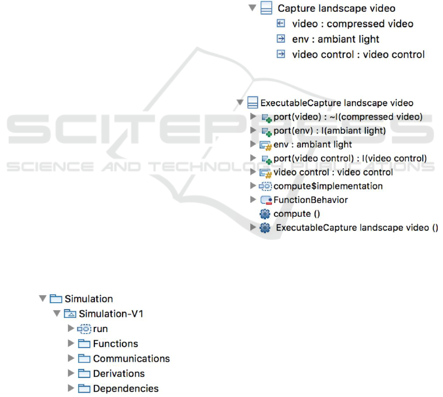
4.2.1 Packages
The model produced from the abstract functional
specification is organized into packages:
Functions: this package contains the
executable version of the functions designed by
the system architect.
Communications: this package contains
signals used to communicate between
functions. It also contains interfaces that
transformed functions require or provide to
send or receive signals.
Derivations: this package contains the links
used to make the relationships between the
abstract functional specification and the
executable model. The sterotype for these links
is Derive.
Dependencies: this package contains a set of
Dependency links. They represent the
relationship between a port, and a property
within the model generated.
Figure 4: The organization of the model generated.
4.2.2 Functions
An abstract functional specification is an UML
composite structure. The graph formalized within this
structure is a network of communicating functions
(see Figure 2). The first step of the transformation is
to replicate this network in the Communications
package. While the result looks very close to the
original model, the transformation makes some
changes to make the model executable.
Let’s consider the mapping of function
CaptureLandscapeVideo in Figure 5. The class
ExecutableCaptureLandscapeVideo in
Figure 6 is the translated version of
CapturelandscapeVideo.
Figure 5: Function Capture landscape video.
Figure 6: Executable version of function Capture landscape
video.
The differences between the original and the
transformed classes are
Class status: the executable class has the UML
active flag set. This implies that when
instantiated, the class can run on its thread of
execution and to communicate asynchronously
with other instances.
Ports: the executable class has the same
number of ports than the original one.
However, these ports are typed with interfaces.
For example, the interface I(ambient
light) provides the capability to receive the
signal S[ambient light] (see Figure 6).
This interface types the port port(env)
Using fUML Combined with a DSML: An Implementation using Papyrus UML/SysML Modeler
251

which makes any instance of
ExecutableCaptureLandscapeVideo
able to receive signals encapsulating the data
ambient light. The generation of these
elements (signals and interfaces) is rationalized
by the need to move from a model not
compliant with PSCS to a conformable one.
The compliance to PSCS ensures the functional
specification to become executable.
Properties: the executable class has as many
properties as the number of input ports owned
by the class it is mapped from. This modeling
choice is rationalized by the need for the
executable class instances to store values
embedded into signals received through its
input ports. Indeed, these signals may not be
received simultaneously and a function
instance is required to wait for the reception of
all initial inputs before computing its outputs.
Based on this semantics,
ExecutableCapturelandscapeVideo
integrates two properties: env and video
control (see Figure 6) which respectively
plays the role of a buffer for values received
through port(env) and port(video
control).
4.3 Simulation Model Behaviour
4.3.1 Function Dataflow Semantics
In the abstract functional specification (i.e., the model
from which the executable functional specification is
generated), there are no behaviors (i.e., functions only
have a structural definition). However, in the
executable functional specification, functions are
expected to be executed according to a dataflow
semantics (i.e., all inputs need to be received before
computing outputs). This model of computations is
not the one supported by executable UML for active
classes. Indeed, fUML states that when a signal is
received by an active class then, it is placed into the
event pool. If when dispatched the signal is accepted
by the classifier behavior then it triggers a run-to-
completion step. Along this step, a signal might be
sent from the active class to its environment. In other
words, fUML and PSCS do not put any constraints
regarding the reception inputs and the productions of
outputs.
We introduced a constraint: all inputs must be
received before computing outputs. Then the
classifier behaviors attached to the various functions
defined in our model needs a form allowing the
expected semantics to be respected, while keeping the
model compliant with executable UML. There is no
added value to get the simulation engineer
implementing this aspect. This, constraint is managed
during the transformation: a classifier behavior
forces all inputs to be received, before computing
outputs. Figure 6 shows such classifier behavior for
ExecutableCaptureLandscapeVideo.
The rules to generate the classifier behavior are the
following:
If the mapped class has input ports then the
init state is a composite and contains as
many regions as the number of input ports. In
this situation, each region specifies the waiting
of an input on a specific port. For instance, in
the init state left region, a waiting for the
signal S[ambient light] is specified.
Also, an activity is added on the transition
leaving state Init[port[env]]. The role
of this activity is to enable the update of the
buffer env with the value embedded in the
signal triggering the transition. Note: if the
mapped class has no input ports then the init
state is simple rather than composite.
The state machine init state always has a
transition to a compute state. If the function
does not need to wait for data then this
transition has a trigger for a Start signal. It is
used to force all functions with no data
dependencies to wait until the other functions
finish their initial run-to-completion step.
Conversely (i.e., for functions with data
dependencies), it remains a completion
transition. The compute state is always added
to the generated state machine. It has an entry
behavior responsible for calling the compute
operation that is generated for the executable
class (see Figure 7).
Notice that the compute state has as many
self-transitions as the number of input ports
specified in the mapped class. This enables the
classifier behavior to trigger the execution of
the compute operation if one of the input
changes.
The executable class state machine in Figure 7 is
intended to run as follows. The initial run-to-
completion state brings the state machine into a wait
point where initial inputs for ports env and video
control are expected. When both inputs are
received, then completion transition between init
and compute can be traversed. When entering
compute, the operation compute is called.
This implies the execution of the business logic of the
MODELSWARD 2019 - 7th International Conference on Model-Driven Engineering and Software Development
252
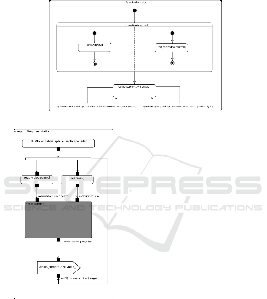
Figure 7: ExecutableCaptureLandscapeVideo classifier behavior.
Figure 8: Implementation of the activity compute.
function according to the received data. At this point,
the state machine enters a new wait point. It will be
allowed to exit, only if the one of the expected input
changes.
4.3.2 Function Business Logic
All compute operations generated for executable
classes are implemented as activities. The simulation
engineer uses these activities to specify the business
logic of the simulated functions. In each activity, the
behavior model is isolated in a structured activity
node (see section 16.14.55 in (fUML, 2018)). This
structured activity node may have input and output
pins. Input pins provide access to input data received
by the function while the output pins enable to
propagate values produced by the function to its
environment. Parts of the activity dedicated to read
the inputs and compute the outputs are generated
automatically. Subsequently, the simulation engineer
updates only the structured activity node. Figure 8
shows the activity implementing the compute
operation after the transformation of the function
Capture landscape video.
4.4 Simulation Instantiation
The initialization of the simulation model is
performed by the generation of an activity called
Run. This activity is the entry point of the simulation
model. It instantiates the function network, and
triggers the execution of all functions that don’t need
to wait for data. This triggering relies on the sending
of a Start signal to these functions. In a situation
where the model has bidirectional dependencies
between functions, the simulation engineer should
define how to solve the dependencies and put default
data on functions’ inputs identified as weak
dependencies.
Using fUML Combined with a DSML: An Implementation using Papyrus UML/SysML Modeler
253

4.5 Traceability
The transformed model maintains a strong
relationship with the abstract functional specification
designed by the system architect. The traceability
links are formalized as UML abstraction (see
section 7.8.1 in (OMG, 2017b) relationships with the
Derive stereotype applied. These relationships are
used during the simulation by the animation engine,
and the debugger to analyze the data flowing between
functions at the abstract functional specification level
(i.e., the one the system architect is working on).
By this way, the system architect can analyze his
model, as if it is an executable one. But behind the
scene a transformed model is running.
4.6 Implementation
The work described above is fully implemented with
the operational query view transformation language
(QVTo). It is included in the Papyrus customization
developed by Safran. With that language, the
implementation was easy, because of the tight
integration with the Papyrus application
programming interfaces (API). No performance
issues were noticed during our tests.
4.7 Related Works
There were many proposals to produce simulation
models from SysML models. Works achieved in (G.
Kapos et al., 2014) and (Bocciarelli et al., 2012)
highlight some of them. The first proposal is to
transform SysML models to DEVS models while the
second proposal is to transform SysML models to
HLA models. While the target languages are
different, the underlying objective is the same: make
sure that output models conform to language with
precise semantics. This ensures that these models can
be used in a simulation since they can be
unambiguously interpreted. The approach presented
in this paper follows the same objective. However, it
differs from existing approaches in two aspects. First,
it keeps the simulation model in the same
environment as the one it is derived from. This has
the advantage to let the simulation engineer to work
in the same environment as the system architect. In
addition, it maintains a strong relationship between
both models. Second, the simulation model is
compliant with the executable UML subset identified
in fUML, PSCS and PSSM. Debugging can be
performed at the transformed model level or from the
original model.
5 CONCLUSIONS
The design of executable UML models requires a
deep knowledge of UML and the fUML standard.
This can be a problem, because unlike software
engineers, systems architects for example are not
familiar with these languages. Then executable UML
languages is not widely used in the industry to model
systems architecture.
We explored a way to reduce this barrier by
generating executable UML model from a higher
abstraction model like a system architecture model.
Then the system architect is not disturbed by the
details and the rigor of fUML. He stays focused on
his work, and use a DSML to model the system at the
right level of abstraction. On the other side, the
simulation engineer requires a formal language to
design an executable model. Then the translation of
the architecture model to an executable UML model
satisfy his requirements.
With this method, we keep the consistency between
the system architect activity and the simulation
engineer activity. Like that, the simulation engineer
doesn’t need to recapture the system architecture
mode model during the handover.
In our work, we used only the graphical notation of
UML to design the executable model. We can
improve the process by using scripting languages
with the UML notations. For example, it is faster to
define an addition or a subtraction with Python or
Javascript than using the UML notation.
So, the next step is dedicated experiments the support
of scripting language, but also to extend the
translation to other executable languages like
Simulink™ or Modelica®. In that case the scope shall
include the physical level. The objective here is to
keep the interfaces defined at the architecture level
consistent between the modeling languages, all along
the MBSE process using a model interface
coordination (Bailey et al., 2018).
REFERENCES
Bailey, W.C., Che, J., Tsou, P., Jennings, M., 2018. A
framework for automated model interface coordination
using SysML. J. Comput. Inf. Sci. Eng. 18.
https://doi.org/10.1115/1.4039474.
Bocciarelli, P., D’Ambrogio, A., Fabiani, G., 2012. A
model-driven approach to build HLA-based distributed
simulations from SysML models.
Cameron, B., Adsit, D.M., 2018. Model-Based Systems
Engineering Uptake in Engineering Practice.
https://doi.org/10.1109/TEM.2018.2863041.
MODELSWARD 2019 - 7th International Conference on Model-Driven Engineering and Software Development
254

G. Kapos, V. Dalakas, A. Tsadimas, M. Nikolaidou, D.
Anagnostopoulos, 2014. Model-based system
engineering using SysML: Deriving executable
simulation models with QVT, in: 2014 IEEE
International Systems Conference Proceedings.
Presented at the 2014 IEEE International Systems
Conference Proceedings, pp. 531–538.
https://doi.org/10.1109/SysCon.2014.6819307.
OMG, 2018. Precise Semantics of UML Composite
Structures version 1.1 [WWW Document]. URL
https://www.omg.org/spec/PSCS/1.1/PDF (accessed
9.26.18).
OMG, 2017a. The OMG System Modeling Language
Specification Version 1.5 [WWW Document]. URL
https://www.omg.org/spec/SysML/1.5/ (accessed
9.26.18).
OMG, 2017b. The Unified Modeling Language
Specification Version 2.5.1 [WWW Document]. URL
https://www.omg.org/spec/UML/2.5.1/ (accessed
9.26.18).
OMG, 2017c. The Semantics of a Foundational Subset for
Executable UML Models Specification Version 1.3
[WWW Document]. URL
https://www.omg.org/spec/FUML/1.3 (accessed
9.26.18).
OMG, 2017d. Precise Semantics of UML State Machines
[WWW Document]. URL
https://www.omg.org/spec/PSSM/1.0/Beta1/PDF
(accessed 9.26.18).
Theobald, M., Palladino, L., Virelizier, P., 2018. About
DSML design based on standard and open-source -
REX from SAFRAN tech work using Papyrus-SysML.
Int. J. Electr. Electron. Eng. Telecommun. 7, 70–75.
https://doi.org/10.18178/ijeetc.7.2.70-75.
Using fUML Combined with a DSML: An Implementation using Papyrus UML/SysML Modeler
255
