
DNA Detection Method based on the Microbead Velocity under
Traveling Wave Dielectrophoresis
Zhenhao Ding
1
, Michihiko Nakano
2
and Junya Suehiro
2
1
Graduate School of Information Science and Electrical Engineering, Kyushu University, 744 Motooka, Fukuoka, Japan
2
Faculty of Information Science and Electrical Engineering, Kyushu University, 744 Motooka, Fukuoka, Japan
Keywords: DNA Detection, Traveling Wave Dielectrophoresis, Microbeads.
Abstract: Polymerase chain reaction (PCR) is a highly specific and sensitive detection method for bacterial and viral
infections by amplifying the specific regions of DNA or RNA via enzymatic reaction. The authors have
developed a rapid DNA detection method based on the dielectrophoresis (DEP) characteristic of DNA
labeled microbeads for the rapid detection of the DNA that amplified by PCR. This method is based on the
change of the Clausius-Mossotti (CM) factor K of DEP when DNA is attached onto microbeads. In former
studies, we developed a new DNA detection method based on the change of the real part of K (Re[K]).
However, this method requires a large amount of DNA attaching to a microbead to alter the microbead DEP
behaviour for DNA detection. In this study, we focus on the imaginary part of K (Im[K]), which
theoretically will change more dramatically than Re[K] when DNA is attached onto the microbeads. Since
the traveling wave dielectrophoresis behaviour is based on the Im[K], we propose a new method for DNA
detection based on the traveling wave dielectrophoresis (twDEP) of microbeads.
1 INTRODUCTION
There are various diseases caused by bacterial or
viral infections. In order to select an appropriate
treatment for an infectious disease, the early
detection and identification are extremely important.
A nucleic acids amplification assay is a highly
sensitive and specific method among various
diagnosis methods for infectious diseases. The
polymerase chain reaction (PCR) is a type of nucleic
acids amplification assay, which is well developed
for clinical applications. The PCR is used to amplify
specific regions of DNA or RNA of a target
pathogen via enzymatic reaction. The amplicons
amplified by PCR are generally detected by the
agarose gel electrophoresis, which is well
established and reliable. However, the agarose gel
electrophoresis requires time-consuming manual
operation by experts.
The authors develop and demonstrate a novel
electrical method for rapid detection of amplicons by
dielectrophoresis (DEP) of microbeads (Nakano et
al. 2014). In the method, the amplicons are
chemically attached to dielectric microbeads so that
the DNA attaching alters the surface conductance of
microbeads and result in the change of Clausius–
Mossotti (CM) factor K of DEP. When enough
amount of DNA is attached to the microbeads, the
real part of K (Re[K]) will change from negative to
positive, which means the DNA-labeled microbeads
will be trapped on a microelectrode under the action
of positive DEP, whereas pristine ones are not
trapped. Combining this dramatic alteration in DEP
phenomena with impedance measurement allows
rapid and quantitative detection of the amplicons,
and can be used for bacterial detection (Ding et al.
2016). However, this method requires a large
amount of DNA attaching to a microbead to alter the
microbead DEP behaviour for DNA detection.
In this study, we propose a new DNA detection
method based on the traveling wave
dielectrophoresis (twDEP), which is a phenomenon
affected by the imaginary part of K (Im[K]). Since
the Im[K] will change more dramatically than Re[K]
against DNA attachment on the microbeads when
microbeads surface conductance is small, the twDEP
can lead to a more sensitive detection of DNA. Since
the velocity of microbeads will change due to
different twDEP forces, we measured the velocity of
DNA labeled microbeads under twDEP force using
computer-based image analysis.
Ding, Z., Nakano, M. and Suehiro, J.
DNA Detection Method based on the Microbead Velocity under Traveling Wave Dielectrophoresis.
DOI: 10.5220/0007341800210025
In Proceedings of the 12th International Joint Conference on Biomedical Engineering Systems and Technologies (BIOSTEC 2019), pages 21-25
ISBN: 978-989-758-353-7
Copyright
c
2019 by SCITEPRESS – Science and Technology Publications, Lda. All rights reserved
21
2 THEORY
DEP is the electrokinetic motion of dielectrically
polarized materials in non-uniform electric fields,
and it is currently an active area of research for
manipulation of biological particles and
nanomaterials, including bacterial cells and DNA
molecules (Pethig, 2010, Hughes, 2000, Washizu
and Kurosawa, 1990). The DEP force acting on a
spherical dielectric particle of radius r suspended in
a medium of absolute permittivity ε
m
is given by as
follows
2
Re
(1)
where E is the magnitude of the applied field.
Re[K(ω)] is the real component of the Clausius–
Mossotti (CM) factor, given by
∗
∗
∗
2
∗
(2)
where ε
*
p
and ε
*
m
are the complex permittivities of
the particle and the surrounding medium,
respectively. For a real dielectric, the complex
permittivity is defined as ε
*
= ε-j(σ/ω), where ε is the
permittivity, σ is the conductivity of the dielectric,
and ω is the angular frequency of the applied electric
field. When Re[K(ω)] has a positive value, the
particle is propelled toward the high field region
(positive DEP, p-DEP). With a negative value of
Re[K(ω)], the particle is repelled from the high field
region (negative DEP, n-DEP).
The conductivity of a solid dielectric particle, σ
p
,
can be expressed by the following equation (Zhou
et
al.
1995, Ermolina and Morgan, 2005).
2
(3)
where σ
b
and K
s
are the bulk conductivity and the
surface conductance of the particle. Equations 1–3
imply that the dielectric properties and the resultant
DEP force acting on a smaller particle should be
more dependent on the surface conductance K
s
.
Hughes et al. reported that antibody (protein)
coating of submicrometer latex spheres altered the
surface conductance and DEP spectrum of the
particles, enabling the separation of unlabeled and
protein-labeled particles (Hughes and Morgan,
1999).
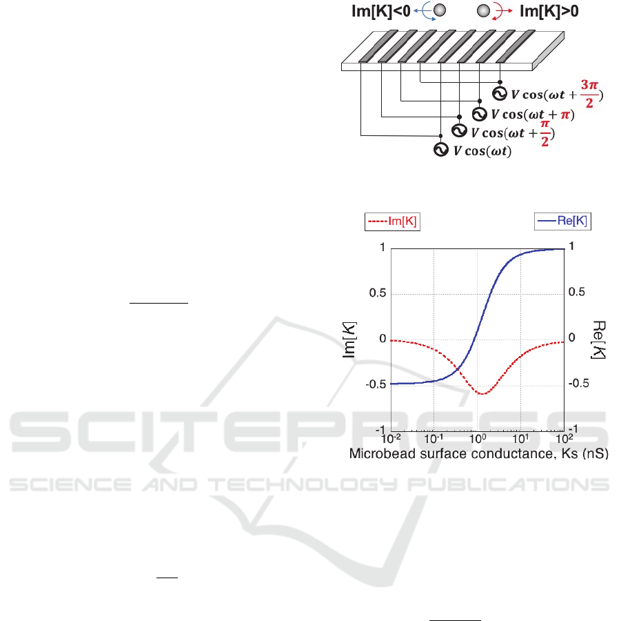
Figure 1: The twDEP of microbeads under four voltage
waveforms with shifted phase.
Figure 2: Calculation results of relationship between
microbeads surface conductance and Re[K], Im[K].
The twDEP will be generated when the electric field
has a spatially varying phase. When the electrodes
are equally spaced, the phase angle change across
each electrode will be the same. The twDEP force is
given by (Cheng et al. 2009, Fathy et al. 2017):
4
Im
(4)
where is the distance between every four
electrodes. Microbeads will experience twDEP force
against or along the direction of field travel when the
Im[K] is positive or negative as shown in Fig. 1. The
theoretical calculation results of relationship
between microbeads surface conductance and Re[K]
as well as Im[K] are shown as Fig. 2. The voltage
frequency used in the calculation is 100 kHz. The
Im[K] changed more dramatically than Re[K] when
microbeads surface conductance is small (less than
0.2 nS), which means Im[K] will change more
dramatically when less DNA was attached on the
microbeads. Since the twDEP force is associated
with the Im[K] and change the velocity of the
BIODEVICES 2019 - 12th International Conference on Biomedical Electronics and Devices
22
microbeads, the target DNA can be detected more
sensitively by measuring the velocity of microbeads
under the twDEP.
3 EXPERIMENTS
We used pUC 19 DNA as the template for PCR. The
5’ end of forward primers were labeled with biotin.
As the results of PCR, 391 bp DNA were amplified
and the amplicons were confirmed by standard
agarose gel electrophoresis.
Magnetic microbeads (Dynabeads
®
M-280, Life
Technologies 2.8 μm in diameter) were used in this
experiment. The surface of the microbead was
coated with streptavidin, which binds specifically to
biotin. Microbeads (3x10
4
beads/μl) were mixed
with the reaction solution (5 mM Tris-HCl (pH 7.5),
0.5 mM EDTA, 1 M NaCl), including the
amplicons. The amplicon concentrations in the
solution were 3.5x10
7
copies/μl and 3.5x10
8
copies/μl, which make the ratio of DNA to
microbeads as 10
3
: 1 and 10
4
: 1, respectively. The
mixtures of the amplicons and microbeads were
incubated at room temperature for 30 minutes.
Hence, the microbeads were labeled with amplicons
via biotin-streptavidin interaction. Then, the DNA
labeled microbeads were suspended in deionized
water (conductivity 4 × 10
−4
S/m).
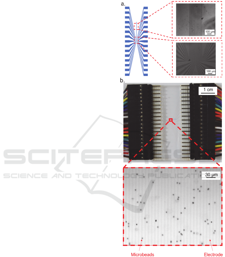
In order to manufacture the Indium Tin Oxide
(ITO) microelectrode with 30 fingers, the glass
substrate with ITO thin film (Narika, Inc.) was used.
The microelectrode was fabricated by
photolithography and wet etching. The schematic
diagram and microscope image of the micro
electrode were show as figure 3.a. The ITO
microelectrode, which is transparent, was chosen in
this study in order to simplify the process of velocity
analysis by computer-based image analysis.
20 μl of the solution containing the DNA-labeled
microbeads was placed on the microelectrode and
covered with a cover slip. The microscope image of
the microbeads solution at the detection region was
shown as figure 3. b. Then the voltage (6 Vp-p, 100
kHz) was applied on the microelectrode with 90-
degree phase shift between each electrode fingers to
generate twDEP and the twDEP was confirmed by
microscope observation. As a result, the microbeads,
which were shown in figure 3.b. moved horizontally
to the left. The movements of microbeads were
recorded by a CCD camera at 100 fps and used for
velocity analysis.
Figure 3: a. The schematic diagram and microscope image
of the microelectrode; b. The photo of the electrode and
the microscope image of detection region after the
microbeads solution was placed on the microelectrode.
The velocities of microbeads were analysed by
image analysis software Image-Pro (Media
Cybermetics Inc). The trajectories of microbeads
DNA Detection Method based on the Microbead Velocity under Traveling Wave Dielectrophoresis
23
inside the detection region were automatically
tracked and analysed.
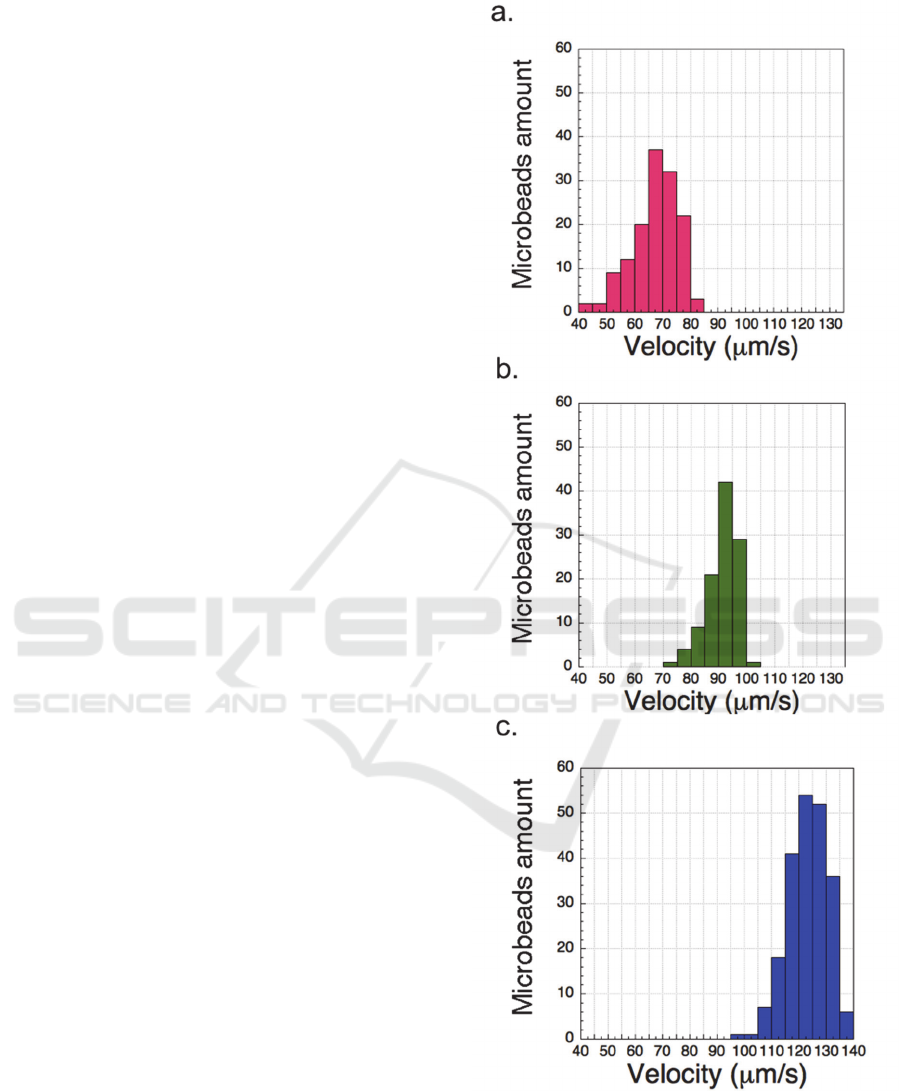
4 RESULTS AND DISCUSSION
The velocity of bare microbeads and DNA labeled
microbeads at ratio of 10
3
and 10
4
copies DNA to 1
microbead was shown in figure 4.a. b. and c.
respectively. The velocity of microbeads distributed
in a range of velocities. The main reason was that
the amount of DNA attached to each microbead was
not perfect uniform.
The average velocity of bare microbeads and
DNA labeled microbeads at ratio of 10
3
and 10
4
copies DNA to 1 microbead was calculated and
shown in figure 5. The average velocity of
microbeads increased as the labeled DNA amount
increased. This is because the increase of labeled
DNA will result in the increase of the surface
conductance of microbeads. As shown in figure 2,
the Im[K] will increase against the increase of
microbead surface conductance when the surface
conductance is small. Hence, the twDEP force that
microbeads experienced would increase along with
the increase of labeled DNA and result in the
increase of the average velocity as shown in the
figure 5.
As shown in figure 5, the velocity of microbeads
under twDEP force can only be measured when less
than 10
4
copies of DNA attached on 1 microbead.
This was because the twDEP would only occur
when the Re[K] was negative. When the Re[K] was
positive, the microbeads would experience positive
DEP and be trapped to the gap of microelectrode.
Hence, the microbeads would not be able to move
upon the electrode. Since the microbeads would
experience positive DEP when the ratio of DNA to
microbeads was above 10
5
:1, the twDEP would
only occur when the labeled DNA was less than 10
5
copies on 1 microbead. Hence, the velocity of
microbeads under twDEP force can be measured
when less than 10
4
copies of DNA were labeled on 1
microbead as shown in figure 5. However, when the
Re[K] was positive, which means the microbeads
would be trapped between the microelectrode and
induce the impedance change of the microelectrode
as former proposed method (Nakano et al. 2014).
Hence, the detection sensitivity can be increase by
applying the twDEP and the detection range can be
increase by combine the former method and twDEP
based method.
Figure 4: The velocity of a. bare microbeads; b. DNA
labeled microbeads at ratio of 10
3
copies DNA to 1
microbead; c. DNA labeled microbeads at ratio of 10
4
copies DNA to 1 microbead.
BIODEVICES 2019 - 12th International Conference on Biomedical Electronics and Devices
24
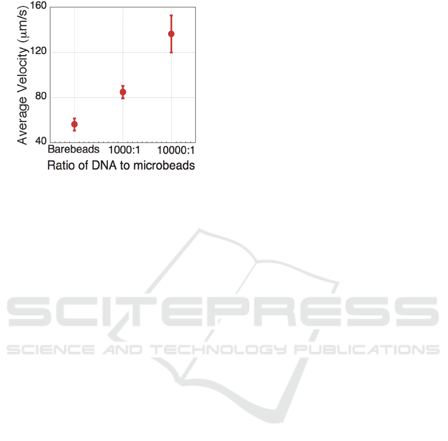
Figure 5: The velocity of bare microbeads and DNA
labeled microbeads at ratio of 10
3
and 10
4
copies DNA to
1 microbead.
5 CONCLUSION
The velocity of DNA labeled microbeads under
twDEP was measured and analysed by image
analysis. The average velocity of DNA labeled
microbeads would increase along with the increase
of the amount of the labeled DNA when the ratio of
DNA to microbead is above 10
3
: 1. Since the former
proposed method required the amount of DNA to
alter the DEP force from negative to positive, which
requires the amount of DNA to achieve the ratio of
DNA to microbeads above 10
5
: 1, this method can
increase the sensitivity of rapid DNA detection
based on the twDEP. Furthermore, by combing this
method with the former proposed method, the
detection range of DNA can be increased as well.
For example, by measuring the impedance change of
the electrode as well as the velocity of the
microbeads after unknown amount of DNA labeled
microbeads placed on the microelectrode, the DNA
can be detected as long as there were more than 10
3
copies of DNA labeled on one microbeads.
ACKNOWLEDGEMENTS
This work was partly supported by JSPS KAKENHI
Grant number JP17H03277.
REFERENCES
Cheng, I.-F., Froude, V. E., Zhu, Y., Chang, H.-C. and
Chang, H.-C., 2009, A continuous high-throughput
bioparticle sorter based on 3D travelling-wave
dielectrophoresis, Lab on chip, 9, 3193-3201.
Ding, Z., Kasahara, H., Nakano, M. and Suehiro, J., 2017.
Bacterial detection based on polymerase chain reaction
and microbead dielectrophoresis characteristics. IET
Nanobiotechnology, 11, 562-567.
Ermolina, I. and Morgan, H., 2005. The electrokinetic
properties of latex particles: comparison of
electrophoresis and dielectrophoresis. Journal of
Colloid and Interface Science, 285, 419-428.
Fathy, J., Pourmand, A. and Ghavifekr, H. B., 2017,
Design and simulation of a MEMS based separator
utilizing 3D travelling-wave dielectrophoresis,
Microsystem Technologies, 23, 1351-1360.
Hughes, M. P. and Morgan, H., 1999. Dielectrophoretic
characterization and separation of antibody-coated
submicrometer latex spheres. Analytical Chemistry,
71, 3441-3445
Hughes, M. P., 2000. AC electrokinetics: applications for
nanotechnology. Nanotechnology, 11, 124-132.
Nakano, M., Ding, Z., Obara. R., Kasahara, H. and
Suehiro, J., 2014. Rapid DNA detection based on
direction reversing of dielectrophoresis of DNA-
attached microbeads. Biosensor 2014.
Pethig, R., 2010. Review article-dielectrophoresis: status
of the theory, technology and applications.
Biomicrofluidics, 4, 022811.
Washizu, M. and Kurosawa, O., 1990. Electrostatic
manipulation of DNA in microfabricated structures.
IEEE Transactions on Industry Applications, 26,
1165-1172.
Zhou, X. F., Markx, G. H., Pethig, R. and Eastwood, I.M.,
1996. Effect of biocide concentration on
electrorotation spectra of yeast cells. Biochimica et
Biophysica Acta, 1281, 60-64.
DNA Detection Method based on the Microbead Velocity under Traveling Wave Dielectrophoresis
25
