Combining Two-level Data Structures and Line Space Precomputations
to Accelerate Indirect Illumination
K. Keul, T. Koß, F. L. Schr
¨
oder and S. M
¨
uller
Institute for Computational Visualistics, University of Koblenz-Landau, Germany
Keywords:
Visualization, Ray Tracing, Data Structures.
Abstract:
We present a method for combining two-level data structures and directional precomputation based on the
Line Space (LS). While previous work has shown that LS precomputation significantly improves ray traversal
performance of typical spatial data structures, it suffers from high memory consumption and low image quality
due to internal approximations. Our method combines this technique with two-level BVHs, where the LS is
integrated within second-level object BVHs. The advantages are, among others, optimizations in terms of
approximation accuracy and required memory. In addition, we propose a method to use an accurate BVH in
combination with the fast approximation-based LS for path tracing in order to further reduce image errors of
the LS while still benefitting from its gain in performance.
1 INTRODUCTION
Besides ray tracing acceleration through spatial data
structures, there have been many attempts based on
directional visibility information. Recently, the Line
Space (LS) was proposed as extension of spatial struc-
tures (Keul et al., 2016) (Billen and Dutr
´
e, 2016).
There, rays are clustered and classified within shafts
during initialization. A representative candidate was
used per shaft, which acted as blocker approxima-
tion during runtime (Keul et al., 2018). This accel-
erated ray traversal significantly, however, at the cost
of approximation-based errors in the resulting image
and high memory consumption.
In the context of object instancing and rigid ob-
ject movements, two-level structures are employed,
which build a top-level structure around second-level
object structures. Their performance is in general in-
ferior compared to their single-level flat counterparts
(Benthin et al., 2017). With this work, we first pro-
pose a combination of two-level BVHs and represen-
tative candidate LS precomputations to combine the
advantages of both. Typically, second-level object
bounding volumes of two-level structures are small
and tightly-fit to the contained objects. This property
makes LS approximations more accurate and reduces
image errors, as demonstrated in figure 1. In addition,
less LS nodes need to be generated and therefore less
memory is consumed, especially in scenes that rely
on object instancing.
In a second step, we propose a method for combin-
ing different data structures in path tracing systems.
While BVHs are used on earlier path segments, where
accurate results are needed, approximation-based LS
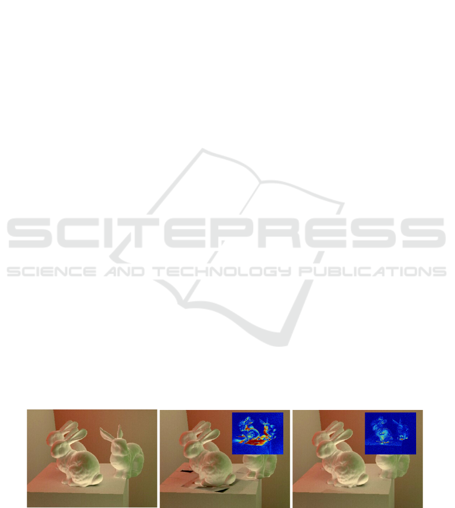
Reference (BVH)
F-LS (10) Ours: 2L-LS (4)
Figure 1: Improvements in indirect lighting calculation. We combine two-level BVHs with an approximation-based represen-
tative candidate Line Space (2L-LS). Even with a lower depth parameter (in brackets), we achieve less approximation errors
compared to a LS integrated in a single-level flat BVH (F-LS). Additionally, less errors appear when used in later bounces.
228
Keul, K., Koß, T., Schröder, F. and Müller, S.
Combining Two-level Data Structures and Line Space Precomputations to Accelerate Indirect Illumination.
DOI: 10.5220/0007345902280235
In Proceedings of the 14th International Joint Conference on Computer Vision, Imaging and Computer Graphics Theory and Applications (VISIGRAPP 2019), pages 228-235
ISBN: 978-989-758-354-4
Copyright
c
2019 by SCITEPRESS – Science and Technology Publications, Lda. All rights reserved

results are used in later path segments, where accu-
racy is less relevant. By this, errors in the final image
are nearly eliminated and the fast performance of the
LS can be used almost without any drawbacks in im-
age quality.
2 RELATED WORK
Indirect lighting calculation and ray tracing systems
are extensively studied topics, which are well pre-
sented in previous work (Ritschel et al., 2012)(Pharr
et al., 2016). Acceleration structures for ray tracing
have been researched intensively as well. Hence, we
present a brief overview of the most relevant litera-
ture in the most related topics of our work. We fo-
cus on bounding volume hierarchies (BVHs), as cur-
rent research suggests, that these result in the highest
ray tracing performance (Havran, 2000) (Zlatu
ˇ
ska and
Havran, 2010) (Vinkler et al., 2016).
Bounding Volume Hierarchies. Since the first au-
tomatic construction algorithm of BVHs was pub-
lished (Kay and Kajiya, 1986), many extensions and
optimizations for BVHs have been proposed (Aila
et al., 2012) (Aila et al., 2013). Most construction
algorithms work in a top-down manner, splitting the
scene along a promising plane in order to narrow the
domain of scene triangles that need to be tested for in-
tersection during runtime (Wald, 2007) (Wald, 2012).
Spatial splits in the BVH (called SBVH) are used
for better arrangement of the bounding volumes, but
lead to higher depths in the hierarchy (Stich et al.,
2009). More recently, SBVHs were optimized for bet-
ter SIMD parallelization (Fuetterling et al., 2016), im-
proved subdivision of the scene triangles (Ganestam
and Doggett, 2016) and better split cost prediction
through temporarily constructed BVHs (Wodniok and
Goesele, 2017). These approaches result in high qual-
ity BVH trees with good performance but higher and
mostly non-interactive construction time.
Construction algorithms based on Morton codes
result in interactive build times with the hierarchical
linear BVH (HLBVH) (Lauterbach et al., 2009) (Pan-
taleoni and Luebke, 2010) (Garanzha et al., 2011).
Recent advances extend Morton codes by also encod-
ing the object size and using adaptive axis order and
bit size to improve the handling of non-uniform scene
distribution (Vinkler et al., 2017). Morton codes were
also used to cluster scene primitives with a parallel ap-
proximate agglomerative clustering method (Gu et al.,
2013) (Meister and Bittner, 2017). Further, the Bon-
sai algorithm was proposed, where subtrees are later
gathered by a top-tree (Ganestam et al., 2015). Re-
cent methods start from fast-initialized HLBVHs that
are optimized afterwards. This can be done by conse-
quent remove-and-insert updates (Bittner et al., 2013)
(Meister and Bittner, 2018), optimization of the spa-
tial splits (Hendrich et al., 2017) or subsequent paral-
lel treelet optimization (Karras and Aila, 2013).
Two-level Data Structures. It is also possible to
use a two-level subdivision scheme with second-level
object hierarchies and a top-level structure that is built
on top of these objects. While the tree quality is typ-
ically worse in comparison to flat (i.e. single-level)
structures, which is due to the irregular tree depth,
two-level approaches grant some benefits. Therein,
dynamic scenes with rigid object animation are im-
plemented through transformation of the previously
built object hierarchies. Object instancing results in
less memory consumption, as the data structure used
per object can be reused. This technique was first
proposed for k-d-trees (Wald et al., 2003), but since
also applied to other data structures like grids (Kalo-
janov et al., 2011) and BVHs in OptiX (Parker et al.,
2010) and Embree (Wald et al., 2014). However,
overlapping object hierarchies lead to multiple ob-
jects that need to be tested for intersections in or-
der to find the nearest intersection point. For this
disadvantage, two-level BVHs were extended by us-
ing partial re-braiding (Benthin et al., 2017), which
opens and merges overlapping object BVHs during
runtime. Also, in comparison to its flat counterpart,
the tree structure of two-level structures is less bal-
anced, which results in inferior SIMT parallelization
when traversing different objects. This disadvantage
is regarded in our approach, as the Line Space is able
to limit the maximum depth of object BVHs to a fixed
level, leading to more balanced hierarchies.
Visibility Structures. In terms of directional data
structures, the accumulation of rays to beams is
known as beam tracing and was shown to result in
good performance, however, at the cost of high mem-
ory consumption and initialization time (Reshetov
et al., 2005) (Mortensen et al., 2007) (Laine et al.,
2009). The general approach is to generate mul-
tidimensional visibility fields around scene objects,
granting precomputed classification schemes for the
contained rays. These methods are for instance used
in radiosity systems (Cohen and Wallace, 2012) or for
accelerated computation of indirect illumination in
ray tracing (Gaitatzes et al., 2010), sometimes based
on approximated results (Bashford-Rogers et al.,
2011).
Newer work introduces the Line Space (LS) as a
classification scheme for rays, which groups the rays
into shafts within a regularly subdivided bounding
box, based on top of a spatial data structure (Keul
et al., 2016) (Billen and Dutr
´
e, 2016). Information is
Combining Two-level Data Structures and Line Space Precomputations to Accelerate Indirect Illumination
229
precomputed based on shafts and applied to all con-
tained rays during runtime. This was used as an ac-
celeration structure on top of grids and BVHs for ap-
proximate soft shadow and indirect lighting calcula-
tions (Keul et al., 2017) (Keul et al., 2018). While the
resulting images have visible artifacts due to the shaft
approximations, it was shown that some artifacts are
negligible when approximations are only used for in-
direct lighting computations (Yu et al., 2009). With
this, the LS is one magnitude faster in ray tracing
performance in comparison to typical data structures.
Besides the image quality, the main disadvantages are
the extensive memory usage and build time that arise
from the high number of precomputed shafts.
3 TWO-LEVEL LINE SPACE
An observation, used in our work, is that approxi-
mation accuracy is higher, when smaller and more
tightly-fitting bounding volumes are used for the LS.
For this purpose, we adapt the LS to two-level BVHs
that grant smaller bounding volume sizes in second-
level object BVHs, leading to higher LS precision.
We first revise the representative candidate LS tech-
nique as proposed by (Keul et al., 2018). Afterwards,
we describe the adaption to two-level BVHs, which is
one of the main contributions of this paper. Lastly, we
give a short discussion of all parameters involved.
3.1 Representative Candidate LS
Tracing cost is dividable in traversal cost of the un-
derlying tree and cost of intersection tests that are
made to find the intersected scene primitive. The rep-
resentative candidate LS finds characteristic intersec-
tion candidates for shafts during initialization. With
this, the tree traversal is cut at a specific level, where
the representative candidate LS nodes are integrated.
Then, instead of calculating intersection tests between
rays and geometric scene primitives, the precomputed
representative shaft candidate approximates the ray
intersection within that shaft. While this improves
performance remarkably, the candidate approxima-
tion leads to visible errors.
The initialization of the representative candidate
LS is straightforward. First, the underlying spatial
data structure (i.e. the BVH) is constructed. Then
a LS node is constructed for every node in a given
depth of the underlying BVH. A LS node is a bound-
ing volume, where all sides of the bounding box sur-
face are subdivided into equally sized patches. Every
two distinctive patches are joined to result in a shaft
connecting those patches. Hence, each ray through
S
E
O
S
E
O
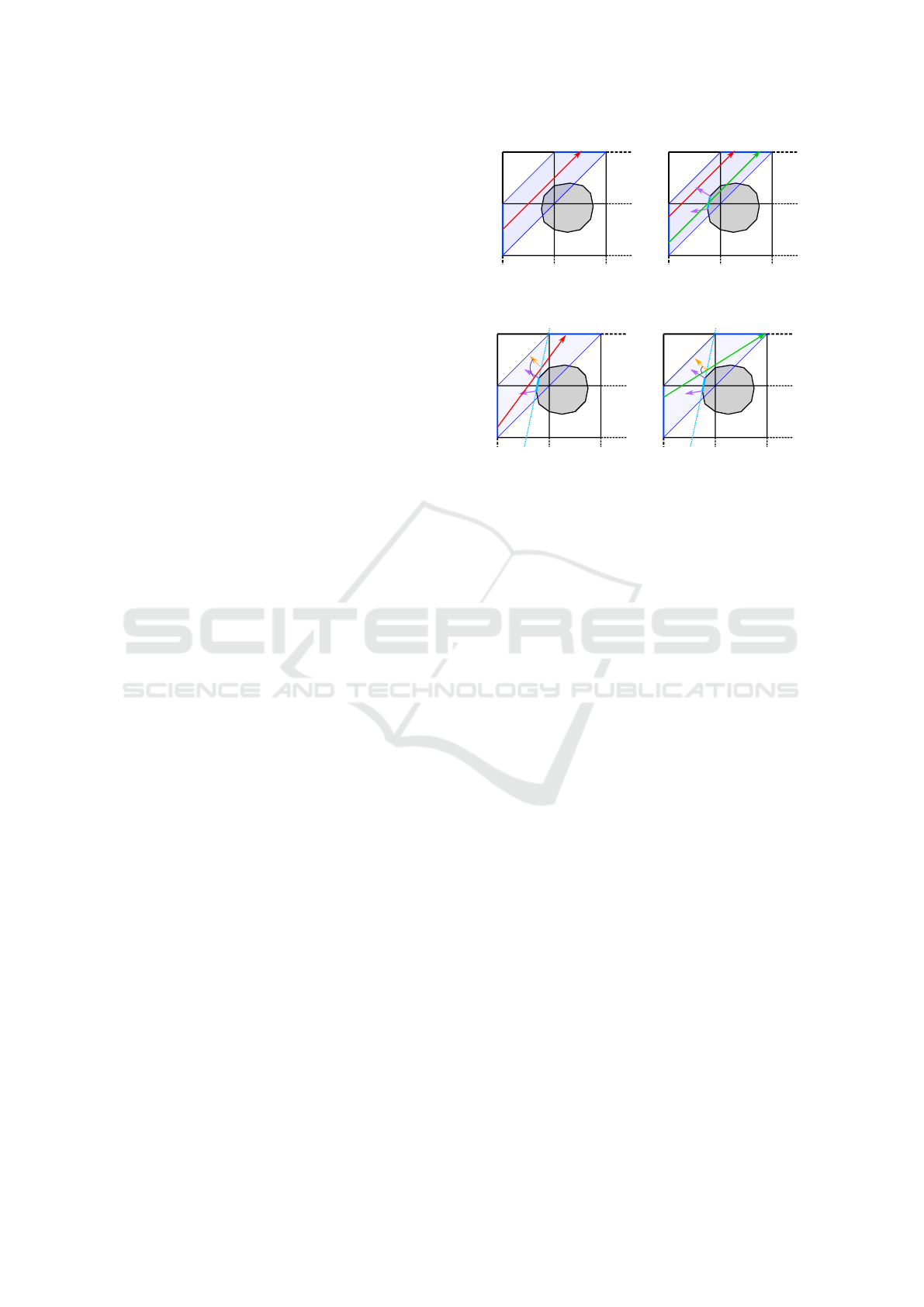
Figure 2: Initialization with representative shaft candidate
search. If the midpoint ray of the shaft between patches S
and E has no intersection (left), further rays are used (right).
P
c
α
P
c
α
Figure 3: Runtime usage of the shaft candidate c. It is used
as ”infinite plane” P for all rays of the shaft. If angle α
between a ray and the extrapolated normal (yellow) is too
big, blocker approximation is refused (left). Otherwise it is
used, even with no actual object intersection (right).
the bounding volume can be assigned to a single shaft.
In the representative candidate LS every shaft has a
triangle reference, which describes the surface of the
scene primitives covered by the shaft. The triangle
(the representative candidate) is found by simple ray
traversal within the underlying data structure during
initialization. The ray used for traversal is determined
by the midpoints of the patches that represent the
shaft. If this ray has no intersection, additional rays
can be traced. If still no intersection was found, the
shaft is declared as empty. This process is shown in
figure 2. During runtime, the representative candidate
is used as a blocker approximation for all rays of the
given shaft, resulting in an ”infinite plane”. However,
if the extrapolated normal of the approximation ex-
ceeds a given threshold, a potential boundary of the
contained object can be assumed, as illustrated in fig-
ure 3. The approximation is then discarded and traver-
sal continues.
3.2 Two-level LS Structure
The main idea of our work is to combine the LS
with previously generated two-level BVHs, that ar-
range logical scene objects on the first level and in-
volve scene primitives only within the second level.
The second-level object BVH nodes have a tighter fit
to their content, which makes them smaller in size
and more beneficial for the LS. This reduces the to-
tal number of LS nodes needed while simultaneously
improving approximation accuracy. We differentiate
four different setups of the data structure, as also vi-
GRAPP 2019 - 14th International Conference on Computer Graphics Theory and Applications
230

Flat BVH
Two-Level BVH BVH-LS (2)
Two-Level BVH-LS (1)
Object Root Node
BVH
Top-Level BVH Geometry
LS
Figure 4: Acceleration structures used. Flat BVHs are the most common structures. Two-level BVHs are used for rigid
object dynamics, granting minimal tree updates for object movements but worse runtime performance. The LS improves
performance, due to early approximation-based traversal termination. Our work combines the LS and two-level BVHs, to gain
fast performance and higher approximation accuracy. The numbers show the integration depth within (object-) hierarchies.
sualized in figure 4:
1. Flat BVH, as state-of-the-art ray tracing structure;
2. Two-level BVH, better suited for rigid object dy-
namics and instancing, but with higher tree com-
plexity and lower runtime performance;
3. Flat BVH with LS integration, for fast blocker ap-
proximations, but with higher memory consump-
tion and visible errors due to approximation, as in
(Keul et al., 2018);
4. Two-level BVH with LS integration, same advan-
tages as two-level BVHs and flat BVH-LS, with
less approximation errors, presented in our work.
The LS adaption improves second-level object
BVHs with LS nodes, that are integrated in a specific
hierarchy depth. Similar to other two-level structures,
the two-level LS is well suited for rigid object dynam-
ics and instancing. This way, every unique logical ob-
ject contains its own BVH-LS, whereas the top-level
hierarchy stores references to those object structures
in its leafs. Therefore, the two-level LS benefits sig-
nificantly from object instancing, as every memory
consuming LS is only stored once per geometrical ob-
ject. Our results further demonstrate, that the perfor-
mance benefit gained through LS approximations out-
performs traditional BVHs, even when used in typi-
cally slower two-level data structures. Because of the
tighter fit to contained objects, the two-level LS im-
proves approximation accuracy, even when less nodes
are generated and less memory is consumed. These
theoretical considerations are summarized in table 1.
As shown in figure 4, two-level structures in gen-
eral result in more unbalanced and partly deeper tree
hierarchies compared to their flat counterpart. This is
especially problematic when complex and simple ob-
jects are used simultaneously. During SIMT traver-
sal, kernels are not able to benefit from thread co-
herency, which decelerates the overall traversal step.
Table 1: Expected results for the data structures. In terms of
quality, flat BVHs and two-level BVHs give correct results,
while LS techniques have better runtime performance.
Memory
Performance
Quality
F-BVH 888 8899 888
2L-BVH 888 8999 888
F-LS 899 8888 899
2L-LS 889 8889 889
Our technique represents a solution to this two-level
imbalance, as the LS limits the maximum object hi-
erarchy depth to a specified level. This, along with
the approximation-based early ray termination, im-
proves SIMT thread coherency and traversal perfor-
mance, due to less overhead caused by bad thread par-
allelism. Concerning BVH initialization, any of the
existing construction or optimization algorithms can
be used. However, bad BVH quality in general re-
sults in larger bounding volumes, leading to bigger
shafts and therefore worse LS approximation accu-
racy. Consequently, a high-quality BVH builder gen-
erates a lower number of nodes, that additionally have
better scene coverage and are smaller in size, which
improves runtime performance and approximation ac-
curacy. Hence, less LS nodes are needed for better
quality and runtime performance. As the top-level
BVH has no connection to the LS, it can be created
with any build algorithm.
3.3 Parameter Discussion
As in previous work, there are two different parame-
ters for our technique: the LS integration depth and
the subdivision parameter. The integration depth is
the depth within the base structure that stores LS
nodes instead of children information. A higher depth
results in a deeper hierarchy, more LS nodes and
therefore higher memory consumption and lower run-
Combining Two-level Data Structures and Line Space Precomputations to Accelerate Indirect Illumination
231
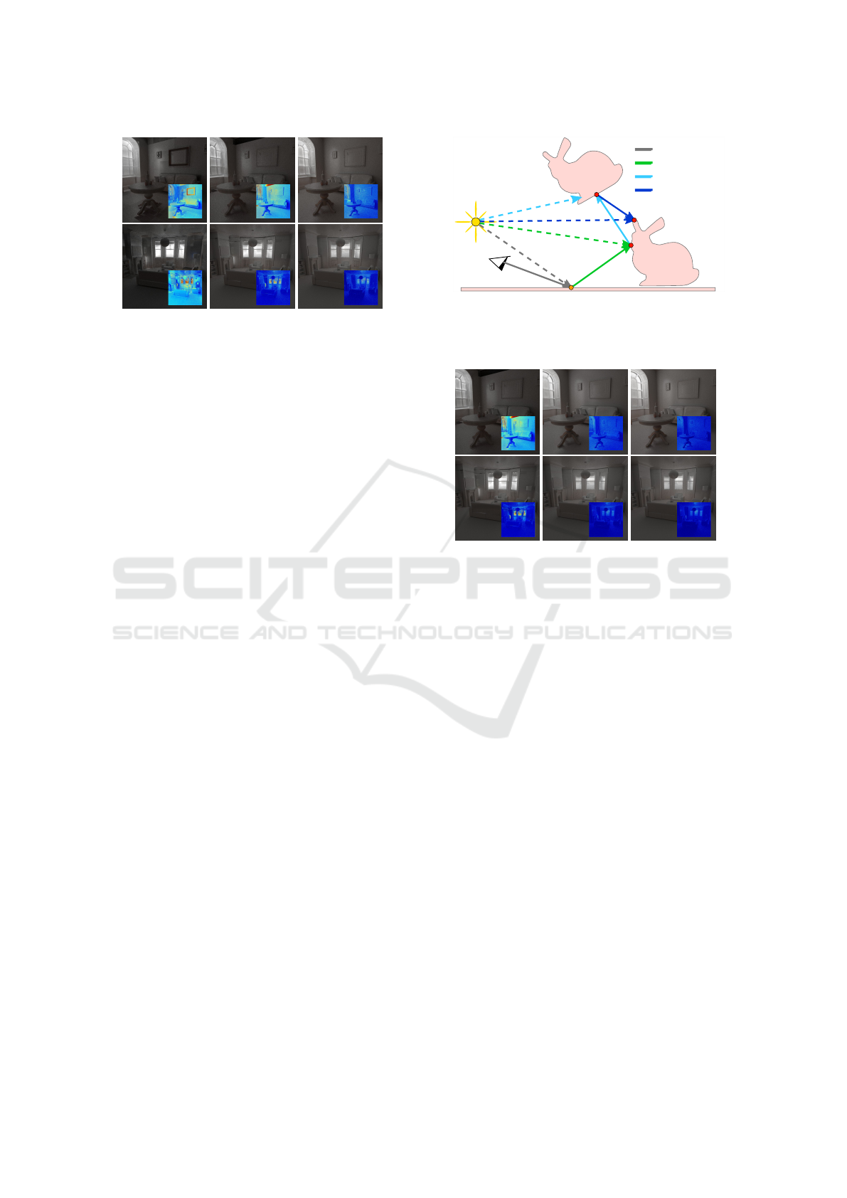
2L-LS (0) 2L-LS (4) 2L-LS (8)
Figure 5: Indirect lighting results of different LS integration
depths (marked in brackets - 0 means root node stores LS).
Higher depths grant better approximations and less errors.
As shown, the needed integration depth is scene dependent.
time performance. However, image quality improves,
due to higher shaft precision. This is demonstrated
in figure 5. The subdivision parameter N determines
LS accuracy. Shafts are created from the surface
patches of the node’s subdivided bounding volume.
Higher subdivision leads to smaller patches and there-
fore thinner shafts and more precise approximations.
Nevertheless, significantly more shafts are generated
and more memory is consumed. In agreement with
previous work, we favor two different parameter val-
ues for N, targeting either low memory consumption
(N = 6) or higher approximation accuracy (N = 10).
The differences in quality are presented in figure 8.
4 PATH TRACING WITH
MULTIPLE DATA
STRUCTURES
The early traversal termination with candidate ap-
proximation of the LS leads to a significant improve-
ment in tracing performance, however, at the cost of
approximation errors. By using an adequate param-
eter set, these errors can be greatly reduced, while
in turn memory consumption increases tremendously.
Keeping this in mind, our goal is to use different pa-
rameter sets and data structures in different segments
of path tracing. With this, we can use the BVH, in sit-
uations that need correct results and the LS with dif-
ferent parameter sets depending on whether the focus
lies on accuracy or tracing performance.
During path tracing, there are several ways to de-
termine, whether a ray can be approximated or should
be calculated accurately. It is possible to use the
evaluation of the probability density function of the
current path segment or to distinguish its type, i.e.
whether a shadow, reflected or diffuse ray is evalu-
Direct
BVH
High Quality LS
Low Quality LS
B0
B1
B2
B3
Figure 6: 3-bounce path using different data structures de-
pending on the bounce depth. Primary and direct shadow
rays use rasterization techniques. BVH path segments have
precise results, while LS segments are traced faster.
1. Bounce 2. Bounce
3. Bounce
Figure 7: Results of different bounce depths of LS us-
age. The number marks the path depth, from which on
approximation-based LS (2L-LS (4)) is used. Later usage
of LS results in less errors as well as less performance gain.
ated. For simplicity, we make this distinction based
on the bounce depth of the current path segment in a
backward path tracing system. There, the first bounce
(indirect illumination through one object) and its ac-
cording shadow ray are calculated correctly with a
BVH. The second bounce (indirect illumination with
two intermediate objects) is less relevant and there-
fore calculated with the faster approximation-based
LS. Further rays have decreasing relevance in illumi-
nation and are calculated with a lower-quality higher-
performance LS. This process is illustrated in figure
6 and with the resulting errors demonstrated in figure
7. Primary rays and the according shadow rays can be
rendered with rasterization-based approaches, which
are fast and generate correct results.
5 RESULTS
We tested and compared our two-level LS approach
(2L-LS) as approximation-based method for indirect
lighting calculation. Our test setup is comparable to
(Keul et al., 2018), where the single-level flat BVH-
GRAPP 2019 - 14th International Conference on Computer Graphics Theory and Applications
232
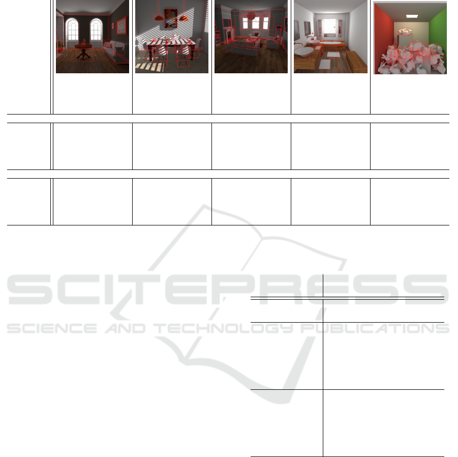
Table 2: Construction results of the single-level flat BVH-LS (F-LS) and the two-level BVH-LS (2L-LS) in terms of the total
number of generated LS, memory consumption (in MB) and build time (in s). The integration depths are shown in brackets.
FIREPLACE
143k triangles
49 objects
BREAKFAST
269k triangles
45 objects
LIVING ROOM
576k triangles
78 objects
SALLE DE BAIN
1231k triangles
39 objects
BUNNY SCENE
4467k triangles
64 instances
Structure
#LS
MB
s
#LS
MB
s
#LS
MB
s
#LS
MB
s
#LS
MB
s
N = 6, ≈ 38k shafts per LS
F-LS (8) 226 28.1 0.82 186 26.4 1.58 198 38.4 1.58 207 53.4 3.07 245 141.2 10.29
F-LS (10) 763 80.9 2.17 641 70.8 4.11 620 81.5 2.77 706 98.0 4.97 954 199.5 13.05
F-LS (12) 2223 206.0 5.83 2185 214.3 12.49 1936 199.1 6.33 2628 238.7 11.90 3750 407.4 23.78
2L-LS (0) 49 8.4 0.81 45 11.0 1.11 78 22.8 1.95 39 35.5 2.64 9 2.5 0.24
2L-LS (4) 526 53.4 1.62 648 68.5 2.89 940 109.2 3.60 467 76.1 3.87 24 3.8 0.29
2L-LS (8) 4195 344.9 8.27 7351 646.5 21.78 7373 631.7 15.92 6296 490.5 18.55 264 20.2 0.98
N = 10, ≈ 300k shafts per LS
F-LS (4) 16 18.0 0.52 16 21.8 1.12 16 29.6 1.36 16 46.9 2.59 16 132.9 9.83
F-LS (6) 63 57.2 1.24 54 51.4 2.70 59 70.1 2.05 59 85.1 3.31 63 170.9 11.01
F-LS (8) 226 184.8 3.78 186 147.1 7.89 198 190.6 4.31 207 194.2 6.66 245 294.4 15.39
2L-LS (0) 49 38.0 1.24 45 35.8 2.05 78 74.7 2.71 39 62.3 3.21 9 7.0 0.30
2L-LS (4) 526 366.7 6.50 648 450.0 14.10 940 708.4 12.66 467 362.1 10.45 24 16.7 0.59
2L-LS (6) 1634 1058.4 19.62 2328 1549.6 47.93 2931 1926.1 37.25 1719 1079.0 32.82 72 42.6 1.49
LS (F-LS) was proposed, which is our main com-
petitor in terms of performance. For a complete
evaluation we also compare against the pure under-
lying structures (F-BVH and 2L-BVH) which pro-
duce approximation-free results. For all BVH al-
gorithms we use state-of-the-art techniques targeting
good tree quality and fast runtime performance, as
shown in (Aila et al., 2012). We compare all meth-
ods in terms of traversal performance, memory con-
sumption and build time. Additionally, we compare
the approximation-based results per bounce to ground
truth data and show, that approximations produced by
our technique are more precise than those of F-LS.
The chosen test scenes are commonly used ar-
chitectural scenes (FIREPLACE ROOM, BREAKFAST
ROOM, LIVING ROOM and SALLE DE BAIN) and a
scene with instanced objects (BUNNY SCENE). These
scenes consist of multiple manually separated ob-
jects, which are used as second-level object BVHs,
as shown in table 3. We use a multiple-bounce path
tracing system for indirect lighting calculation with
different data structures that can be used in different
path depths, as explained in section 4. Image reso-
lution was 1024 × 1024. Primary and direct shadow
rays are not computed via ray tracing, as there are
faster rasterization-based approaches. The test sys-
tem consists of an Intel i7-6800k 3.6 GHz CPU and a
NVidia GeForce GTX 1080 GPU using GLSL Com-
pute Shaders. To guarantee a fair comparison of the
used data structures, we do not use any third party im-
plementations. Overall, the presented results confirm
the theoretical considerations from section 3.2.
Table 3: Path tracing performance and per bounce error of
varying LS integration depth (in brackets) and subdivision
parameter (N) averaged over all scenes.
ALL SCENES Perf RMSE on Bounce
Structure MRays/s 1 2 3
F-BVH 70.7 – – –
2L-BVH 34.3 – – –
F-LS (8) , N = 6 377.0 .030 .011 .004
F-LS (10) , N = 6 313.0 .025 .008 .002
F-LS (12) , N = 6 268.3 .021 .006 .002
2L-LS (0) , N = 6 208.0 .023 .008 .003
2L-LS (4) , N = 6 120.2 .012 .004 .002
2L-LS (8) , N = 6 92.5 .009 .003 .002
F-LS (4) , N = 10 622.6 .044 .019 .006
F-LS (6) , N = 10 440.6 .033 .012 .004
F-LS (8) , N = 10 346.6 .018 .007 .002
2L-LS (0) , N = 10 201.8 .015 .005 .002
2L-LS (4) , N = 10 117.7 .008 .003 .001
2L-LS (6) , N = 10 102.2 .006 .002 .001
Table 2 shows construction results of our method
compared to the single-level LS. We used two differ-
ent subdivision parameters (N = 6 and N = 10) and
three different integration depths, leading to mostly
similar memory consumption for all data structures,
which makes them comparable. Obviously, mem-
ory usage and build time are dependent on the total
number of nodes containing LS information. Hence,
scenes using object instancing have significantly less
memory consumption and by far lower build times in
two-level structures, as shown by the BUNNY SCENE.
Table 3 and figures 1 and 8 show the runtime
Combining Two-level Data Structures and Line Space Precomputations to Accelerate Indirect Illumination
233
BVH
Reference
F-LS (8)
N = 6
F-LS (10)
N = 6
2L-LS (0)
N = 6
2L-LS (4)
N = 6
F-LS (4)
N = 10
F-LS (6)
N = 10
2L-LS (0)
N = 10
2L-LS (4)
N = 10
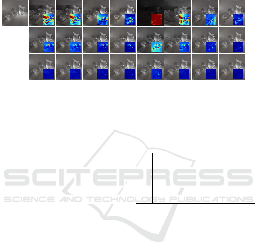
3. Bounce 2.Bounce 1.Bounce
Figure 8: Per bounce results of F-LS and 2L-LS using different parameter sets. Obviously, higher integration depths (in
brackets) and subdivision parameters (N) lead to less errors in the resulting images. In turn, higher parameters in general
result in larger memory consumption, as illustrated by table 2. The exact performance and error values are shown in table 3.
results, i.e. tracing performance and error values
for indirect rays. Approximation-based errors pro-
duced by the LS are specified by RMSE (root-mean-
squared error) values, based on the per-pixel differ-
ences to ground truth data. The bounce depth marks
the depth from which on the shown data structure is
used - earlier bounces use the BVH for correct re-
sults. It is noticeable, that later bounces traced with
approximation-based LS structures lead to insignifi-
cant errors but much faster tracing performance. Two-
level structures in general have inferior performance
in comparison to their single-level flat counterparts,
as explained in section 3.2. In turn, they produce less
errors in general, even with lower depth integration
parameters. Our results also show that higher subdivi-
sion parameters need significantly more memory and
therefore lower integration depths are used, which in
turn reduces approximation accuracy leading to worse
image results. Due to this, higher subdivision pa-
rameters are more suitable for later path segments,
in which the lower integration depth leads to better
performance, while the higher subdivision preserves
accuracy to a higher degree. Summarized results for
different data structures used in different bounces, av-
eraged over all scenes, are shown in table 4.
6 CONCLUSION
We proposed a novel combination of two-level BVHs
and recently introduced LS approximations. We ex-
plained how the combination benefits from both of
their advantages, while also reducing their disadvan-
tages. The object-level LS reduces approximation er-
rors and increases tracing performance by limiting
the integration depth. Consequently, our approach re-
Table 4: Summarized path tracing results with different
data structures for different path segments averaged over all
scenes. Used LS structures are: 2L-LS 1 = 2L-LS(4) N = 6,
2L-LS 2 = 2L-LS(0) N = 10, F-LS = F-LS(8) N = 6.
Data Structure in bounce Average of all scenes (tables 2 and 3)
1 2 3 Memory (MB) MRays/s RMSE
F-BVH F-BVH F-BVH 21.0 70.7 –
F-BVH F-BVH 2L-LS 1 83.2 87.2 .002
F-BVH 2L-LS 1 2L-LS 1 83.2 103.7 .004
F-BVH 2L-LS 1 2L-LS 2 126.8 130.9 .004
F-BVH 2L-LS 2 2L-LS 2 64.6 158.1 .005
F-BVH 2L-LS 1 F-LS 140.7 189.3 .006
F-BVH F-LS F-LS 78.5 274.9 .011
sults in better runtime performance compared to tradi-
tional BVHs, with less memory consumption and ap-
proximation errors compared to single-level LS struc-
tures. Furthermore, we presented a method to con-
nect the strengths of different structures in a multiple-
bounce path tracing system, with a per bounce se-
lection that indicates, whether accurate BVH or fast
approximation-based LS results are used.
In an extensive evaluation we presented the use-
fulness of these approaches, showing different pa-
rameters and per bounce results for the flat BVH-LS
and two-level BVH-LS combination and compared
the results with state-of-the-art techniques. In that,
our evaluation shows that our two-level approach is
an improvement of the flat technique. Moreover, the
two-level approach makes LS approximations usable
in scenes with rigid object animations and especially
useful coupled with object instancing. Finally, the per
bounce usage reduces approximation errors at a high
level, while at the same time enables better LS usage
in combination with traditional data structures.
GRAPP 2019 - 14th International Conference on Computer Graphics Theory and Applications
234

REFERENCES
Aila, T., Karras, T., and Laine, S. (2013). On quality metrics
of bounding volume hierarchies. In Proc. High Perfor-
mance Graphics.
Aila, T., Laine, S., and Karras, T. (2012). Understanding
the efficiency of ray traversal on gpus–kepler and fermi
addendum. NVIDIA Technical Report.
Bashford-Rogers, T., Debattista, K., Harvey, C., and
Chalmers, A. (2011). Approximate visibility grids for
interactive indirect illumination. In Conf. Games and
Virtual Worlds for Serious Applications.
Benthin, C., Woop, S., Wald, I., and
´
Afra, A. T. (2017).
Improved two-level bvhs using partial re-braiding. In
High Performance Graphics.
Billen, N. and Dutr
´
e (2016). Visibility acceleration using
efficient ray classification. Department of Computer
Science, KU Leuven.
Bittner, J., Hapala, M., and Havran, V. (2013). Fast
insertion-based optimization of bounding volume hier-
archies. In Computer Graphics Forum.
Cohen, M. F. and Wallace, J. R. (2012). Radiosity and real-
istic image synthesis. Elsevier.
Fuetterling, V., Lojewski, C., Pfreundt, F.-J., and Ebert,
A. (2016). Parallel spatial splits in bounding volume
hierarchies. In Eurographics Symposium on Parallel
Graphics and Visualization.
Gaitatzes, A., Andreadis, A., Papaioannou, G., and
Chrysanthou, Y. (2010). Fast approximate visibility on
the gpu using precomputed 4d visibility fields. WSCG.
Ganestam, P., Barringer, R., Doggett, M., and Akenine-
M
¨
oller, T. (2015). Bonsai: rapid bounding volume hier-
archy generation using mini trees. Computer Graphics
Techniques 4.
Ganestam, P. and Doggett, M. (2016). Sah guided spatial
split partitioning for fast bvh construction. In Computer
Graphics Forum.
Garanzha, K., Pantaleoni, J., and McAllister, D. (2011).
Simpler and faster hlbvh with work queues. In Proc.
High Performance Graphics.
Gu, Y., He, Y., Fatahalian, K., and Blelloch, G. (2013). Ef-
ficient bvh construction via approximate agglomerative
clustering. In Proc. High Performance Graphics.
Havran, V. (2000). Heuristic ray shooting algorithms. PhD
thesis, Czech Technical University in Prague.
Hendrich, J., Meister, D., and Bittner, J. (2017). Parallel bvh
construction using progressive hierarchical refinement.
In Computer Graphics Forum.
Kalojanov, J., Billeter, M., and Slusallek, P. (2011). Two-
level grids for ray tracing on gpus. In Computer Graph-
ics Forum.
Karras, T. and Aila, T. (2013). Fast parallel construction
of high-quality bounding volume hierarchies. In Proc.
High Performance Graphics.
Kay, T. L. and Kajiya, J. T. (1986). Ray tracing complex
scenes. SIGGRAPH Comput. Graph.
Keul, K., Klee, N., and M
¨
uller, S. (2017). Soft shadow com-
putation using precomputed line space visibility infor-
mation. Journal of WSCG.
Keul, K., Koß, T., and M
¨
uller, S. (2018). Fast indirect light-
ing approximations using the representative candidate
line space. Journal of WSCG.
Keul, K., M
¨
uller, S., and Lemke, P. (2016). Accelerating
spatial data structures in ray tracing through precom-
puted line space visibility. WSCG.
Laine, S., Siltanen, S., Lokki, T., and Savioja, L. (2009).
Accelerated beam tracing algorithm. Applied Acoustics.
Lauterbach, C., Garland, M., Sengupta, S., Luebke, D., and
Manocha, D. (2009). Fast bvh construction on gpus. In
Computer Graphics Forum.
Meister, D. and Bittner, J. (2017). Parallel locally-ordered
clustering for bounding volume hierarchy construction.
IEEE Trans. on Visualization and Computer Graphics.
Meister, D. and Bittner, J. (2018). Parallel reinsertion for
bounding volume hierarchy optimization. In Computer
Graphics Forum.
Mortensen, J., Khanna, P., Yu, I., and Slater, M. (2007). A
visibility field for ray tracing. In Computer Graphics,
Imaging and Visualisation.
Pantaleoni, J. and Luebke, D. (2010). Hlbvh: hierarchical
lbvh construction for real-time ray tracing of dynamic
geometry. In Proc. High Performance Graphics.
Parker, S. G., Bigler, J., Dietrich, A., Friedrich, H., Hobe-
rock, J., Luebke, D., McAllister, D., McGuire, M., Mor-
ley, K., Robison, A., et al. (2010). Optix: a general pur-
pose ray tracing engine. ACM Transactions on Graph-
ics (TOG).
Pharr, M., Jakob, W., and Humphreys, G. (2016). Physi-
cally based rendering: From theory to implementation.
Morgan Kaufmann.
Reshetov, A., Soupikov, A., and Hurley, J. (2005). Multi-
level ray tracing algorithm. ACM Transactions on
Graphics (TOG).
Ritschel, T., Dachsbacher, C., Grosch, T., and Kautz, J.
(2012). The state of the art in interactive global illu-
mination. In Computer Graphics Forum.
Stich, M., Friedrich, H., and Dietrich, A. (2009). Spatial
splits in bounding volume hierarchies. In Proc. High
Performance Graphics.
Vinkler, M., Bittner, J., and Havran, V. (2017). Extended
morton codes for high performance bounding volume
hierarchy construction. In High Performance Graphics.
Vinkler, M., Havran, V., and Bittner, J. (2016). Perfor-
mance comparison of bounding volume hierarchies and
kd-trees for gpu ray tracing. In Computer Graphics Fo-
rum.
Wald, I. (2007). On fast construction of sah-based bound-
ing volume hierarchies. In 2007 IEEE Symposium on
Interactive Ray Tracing.
Wald, I. (2012). Fast construction of sah bvhs on the intel
many integrated core (mic) architecture. IEEE Trans-
actions on Visualization and Computer Graphics.
Wald, I., Benthin, C., and Slusallek, P. (2003). Distributed
interactive ray tracing of dynamic scenes. In Proc.
IEEE Symposium on Parallel and Large-Data Visual-
ization and Graphics.
Wald, I., Woop, S., Benthin, C., Johnson, G. S., and Ernst,
M. (2014). Embree: a kernel framework for efficient
cpu ray tracing. ACM Transactions on Graphics (TOG).
Wodniok, D. and Goesele, M. (2017). Construction of
bounding volume hierarchies with sah cost approxima-
tion on temporary subtrees. Computers & Graphics.
Yu, I., Cox, A., Kim, M. H., Ritschel, T., Grosch, T., Dachs-
bacher, C., and Kautz, J. (2009). Perceptual influence
of approximate visibility in indirect illumination. ACM
Transactions on Applied Perception (TAP).
Zlatu
ˇ
ska, M. and Havran, V. (2010). Ray tracing on a
gpu with cuda–comparative study of three algorithms.
WSCG.
Combining Two-level Data Structures and Line Space Precomputations to Accelerate Indirect Illumination
235
