
The Stray Light Absorption and Anti-photobleaching Capacity of
Matting Materials on Optical System
Rou-Jhen Chen, Chun-Han Cho, Chia-lien Ma, Liang-Chieh Chao, Kuo-Cheng Huang
and Yu-Hsuan Lin
Instrument Technology Research Center, National Applied Research Laboratories, Hsinchu, Taiwan
Keywords: Matting Materials, Stray Light, Anti-photo Bleaching.
Abstract: Eliminating stray light is a very important item in optimizing optical systems. The typical method is to use
matting materials to coat onto the optomechanical component. However, the material will deteriorate or
bleaching after being exposed to long periods of time and high UV energy. The performance of the optical
system will be therefore affected. In this study, the anti-photobleaching capacity of matting materials on
various substrates was discussed. A high intensity UV source was used to radiate the samples for long time.
The changes of the morphology and relative reflectance of sample were observed and analysed. Also, a 355
nm pulsed laser was used to perform the surface modification on samples. An improvement of the matting
performance was expected. This study succeeded in establishing a comparing procedure, which enabled the
characteristic comparison between the various experimental conditions. This study provides a useful
database for the development of matting material technology.
1 INTRODUCTION
Optical systems are widely used in various fields
such as imaging, illumination, and spectral
detection. The modules of its extension are very
versatile and closely related to people's modern life.
In the development process of various consumer and
professional-grade optical systems, the
specifications focused on are often different.
Therefore, it should be optimized for the demand
during the optical design. For example, cameras
require high-quality resolution, light sources require
uniform light field distribution, display systems
require high collimation, and so on. However, all
optical systems always have the same requirement,
that is, less stray light. (Cheng, 2018) (Buisset,
2015) (Williams, 2018). The reason is that these
undesired beams often interfere with the original
ideal optical system. Typical examples are camera
produces ghost and illumination becomes uneven.
They result in a significant drop in optical quality.
Sources of stray light often come from the edges of
optical systems with limited dimensions or the
imperfect lens quality. The beam is constantly
reflected in the system and deviates from the optical
path that was originally expected. This problem can
be overcome by the anti-reflective film coated on the
lens surfaces and the matting materials processed on
the optomechanical component (Patterson, 2003)
(Benjamin, 1962). The anti-reflection coatings were
a common and mature technology, we notice that the
matting process on the optomechanical surface is a
topic worth studying. Generally, it is not difficult to
achieve high-quality stray light elimination under a
low-brightness optical system, but a high radiation
optical system (such as an photo lithographer)
requires a much higher level of extinction capability.
In addition, the matting material also needs to have
excellent anti-bleaching properties in order to make
the optical system have a long service life.
In figure 1, the stray ray distribution of the lens
edge, stop and barrel inner wall of the lithography
light source system by the optical simulation
software was analyzed. The simulation model was
traced by ten million samples. It can be seen from
the figure that since the illuminating light source
cannot be perfectly spatially symmetrical, the
irradiated intensity of the lens edge will be uneven.
If the edge of each lens provides a slight
contribution to the intensity difference, the entire
system will be affected by a non-negligible noise.
This represents a need for matting at the edge of the
lens. For the vicinity of Stop, since the energy is
Chen, R., Cho, C., Ma, C., Chao, L., Huang, K. and Lin, Y.
The Stray Light Absorption and Anti-photobleaching Capacity of Matting Materials on Optical System.
DOI: 10.5220/0007377300590065
In Proceedings of the 7th International Conference on Photonics, Optics and Laser Technology (PHOTOPTICS 2019), pages 59-65
ISBN: 978-989-758-364-3
Copyright
c
2019 by SCITEPRESS – Science and Technology Publications, Lda. All rights reserved
59
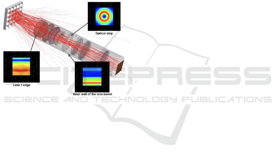
concentrated in the middle of the hole, the beam that
has not been successfully passed will expose the
edge of the hole to form a donut-like shape. This
part of the energy is very high (red area). Therefore,
even though the surface of the Stop has been matted,
it is still prone to failure due to photo bleaching
effect. Finally, the matte treatment of the inner wall
of the lens barrel is inevitable because of it always
encounter a mount of stray lights. In general low-
brightness optical systems, most of them are treated
with black fluffs or black paint. This is not the case
in high-brightness systems, which the scorched
fluffs might contaminate the lens surface. High-
brightness optical systems often use complex surface
modification process, and require good anti-
photobleaching capacity.
Figure 1: Optical intensity distribution of stray light on the
lens edge, stop and inner wall of lens barrel.
In general, the matting treatment on the surface
of the object is divided into two types, one is coating
of the light absorbing material, and the other is
surface modification to form a scattering structure.
A wide variety of light absorbing materials was
formulated for the wavelength match. Some people
created the coating with high melting point and high
absorbance characteristics (Suzanna, 2015)
(Draggoo, 1986) (Jürgen, 2008). The advantages of
these kinds of coating are easily manufacturing and
low cost. The disadvantages of them are that the
absorbances usually lower than 90% and easy to
increase the optical element temperature. The other
people design the diffuser structure on the
optomechanical surface to reduce the effects of stray
ray (Amemiya, 2015) (Mohammad, 2018). A rough
and irregular structure was obtained by destroying
the flatness of the material surface. The specular
reflection behaviour will be converted into diffuse
behaviour, meaning that the directionality of the
light beam will be attenuated by optical scattering.
The advantage of this method is that the extinction
effect is good, but the processing cost is high and
has the risk to damage the optomechanical accuracy.
Surely, the really best way is to combine the two to
achieve a balance between performance and cost. In
this study, a self-made high-intensity UV source was
used to radiate several kinds of matting materials.
The matting materials were coated onto the glass
and metal substrate, and the light exposure time was
over 8 days. By analysing the changes of the surface
structures and relative reflectance, the anti-
photobleaching capacity could be estimated. In
addition, we also try to directly surface-modify these
materials by a UV pulse laser. A novel method was
proposed to increase the matting performance with
the advantages of simple, fast processing and low-
cost. We believe that this study provides a useful
database for matting processing technology.
2 EXPERIMENTAL SETUP AND
SAMPLE PREPARTION
In order to avoid the deterioration of the optical
quality caused by the stray light generated at the
"inner wall of the optical tube" and the "edge of the
lens", a proper design of the matting treatment is
necessary. There are two typical matting treatments,
one is surface modification and the other is black
painting. The former is to manufacture a high-rough
surface to achieve a large amount of optical
scattering, that is, to achieve the extinction by means
of optical diffusion (Diffuse). The effect is very
obvious, but has the disadvantage of high processing
costs. The latter achieves extinction by using an
absorbing material for the wavelength, which is
performance acceptable and inexpensive, but has the
disadvantage of easily accumulating energy to cause
deterioration of the material. In this paper, we
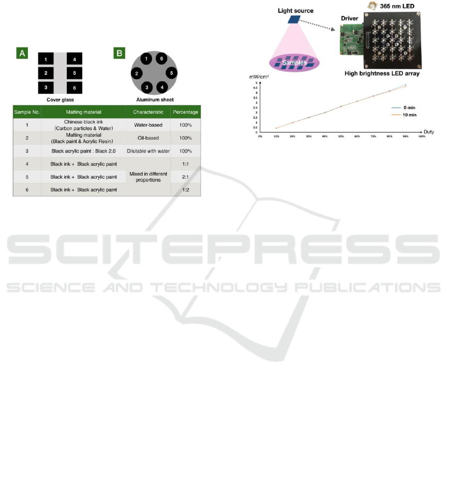
prepared six types of materials as experimental
samples, and were coated on the two types of
substrates. The material information are shown in
Figure 2, where numbers 1~3 are pure matting
materials, and numbers 4~6 are materials mixed in
different proportions. The material types,
characteristics and proportions are also shown in
Figure 2. There are two types of substrates, matte
glass and aluminium metal, which are used to
simulate the "edge of the lens" and the "inner wall of
the optical tube" respectively. The materials was
applied to the substrate in the same manner, and the
position was as shown in the top of Figure 2. The
entire sample has a size of about 10 mm, and the six
PHOTOPTICS 2019 - 7th International Conference on Photonics, Optics and Laser Technology
60
materials are sustained the similar luminance values
during the optical exposure experiment. When
various materials are applied to the substrate, they
will form a slightly rough surface due to cohesive
force, but the contribution of the extinction mainly
comes from the light absorbing ability of the
material. In the second experiment, a pulsed laser
was used to try to form a highly scattering surface
structure on the matting materials.
Figure 2: Configuration diagram of the matting material
and substrate type.
Figure 3 shows the experimental setup. The light
source is a high brightness LED array with a
wavelength of 365 nm. Arranging 25 LEDs in a
square shape makes the illumination more uniform.
The 100mm * 100mm panel size provides a stable
and a large exposure environment. The samples
prepared in Figure 2 are placed in the middle of the
projected range. Before performing the exposure
experiment, the stability of the light source was
verified. As shown in the lower figure in Figure 3,
the linear characterises and intensity did not change
or drift after gradually increasing the electric power
and starting in ten minutes. This plot was measured
when the distance between the sample and the
sensor is 30 cm. The extinction material experiment
was performed for 192 hours, that is, the samples
were exposed to continuous high-intensity
ultraviolet light for 8 days. Each sample receives an
illumination value of approximately 100mW / cm2
and the distance between the sample and the light
source is about 10 mm. Subsequently, the surface
degradation of the material was observed by
confocal optical microscopy to analyse and estimate
the anti-photobleaching capacity of the material. The
confocal microscope used in this study has an axial
resolution of up to 1 μm. Further, in order to make
the matting material have both optical absorption
and structural scattering characteristics, this study
also uses 355 nm pulsed lasers to perform a surface
modification to achieve a better matting
performance. This approach allows for faster and
lower cost surface processing and also can directly
improve the quality of the optical system.
Figure 3: Experimental setup and light source stability test
for anti-photobleaching experiment.
3 RESULTS AND DISCUSSION
To understand the change of the matting material
with time under the exposure of high-intensity
ultraviolet light, an optical confocal microscope was
used to obtain the roughness of the surface of the
sample. The surface morphology of the 12 samples
(two kinds of substrates) were measured after each
day of light exposure. The samples were illuminated
for a total of 8 days, so a total of 96 sets of data were
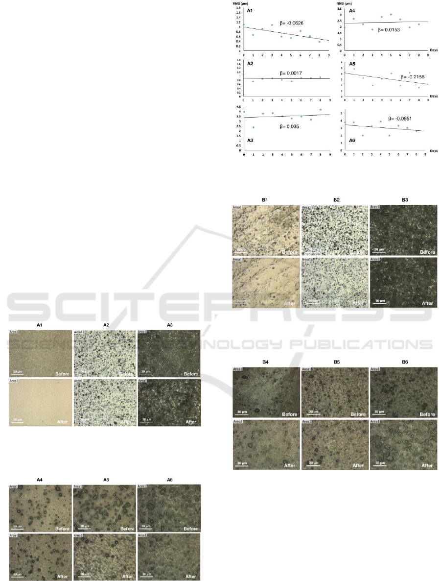
obtained after the end of the experiment. Figure 4
and Figure 5 show the morphologies of the sample
surface before and after light exposure (8 days). The
symbol A indicates the use of a glass substrate, and
No. 1 to 6 individually represents the matting
material shown in figure 3. The measurement results
show that different materials have different particle
and pore distributions. The surface of the sample A1
is fine-grained after light exposure, and therefore it
leads to an increase of the reflected light. The
morphology changes of sample A2 and A4 are not
significant. The sample A3 has a tendency to
increase the particles on surface, and A5 and A6
have significantly less particles. Obviously, the
surface changes of various materials after light
exposure are different.
The surface roughness of the sample determines
the characteristics of light extinction. In general, the
higher the roughness, the better the matting
performance. In the experiment, root mean square
(RMS) roughness of each sample surface was
measured and analysed, as shown in figure 6. The
The Stray Light Absorption and Anti-photobleaching Capacity of Matting Materials on Optical System
61
horizontal axis is the number of exposure days, and
the vertical axis is the measured RMS roughness
value. Since the sample would still be slightly
uneven in each area during the fabrication process,
the change in sample roughness over time should be
represented by a trend line. The β value indicates the
slope of the trend line. We assume that the change is
nearly linear. It can be found that the surface of the
sample A1 has a significantly flattened appearance,
and thus its matting efficiency is lowered. This is
consistent with the results in Figure 4. The surface
morphology of sample A2 is almost unaffected by
the high intensity light exposure, and therefore can
be considered as a matting material with the most
anti-photobleaching characteristics. Although the
sample A3 slowly increase the roughness, it was not
obvious. The samples mixed in different proportions
can theoretically adjust the desired effect. The
sample A5 has a higher contribution of water-based
black ink, so its trend line is similar to the sample
A1. However, it become flatten because it is affected
by the influence of the sample A3. The sample A6
was flatter than A5 because the contribution of the
sample A3 is increased. The most appropriate
proportion may be A4 because its flatness is closest
to A2 and ignore the influence of light exposure. It
means that the sample A4 also has the good anti-
photobleaching capacity.
Figure 4: The morphology changes of the matting
materials (#1~3) on glass substrate after high intensity
light exposure.
Figure 5: The morphology changes of the matting
materials (#4~6) on glass substrate after high intensity
light exposure.
Figure 6: The roughness of different matting materials on
glass substrate varies with exposure time.
Figure 7: The morphology changes of the matting
materials (#1~3) on metal substrate after high intensity
light exposure.
Figure 8: The morphology changes of the matting
materials (#4~6) on metal substrate after high intensity
light exposure.
Figure 7 and Figure 8 show the morphologies of
the sample surface before and after light exposure (8
days). The symbol B indicates the use of a metal
substrate (aluminium), and No. 1 to 6 individually
represents the matting material shown in figure 3.
The measurement results show that different
materials have different particle and pore
distributions. The surface distribution of sample B1
PHOTOPTICS 2019 - 7th International Conference on Photonics, Optics and Laser Technology
62
has lower frequency structures after light exposure.
The morphology changes of sample B2 are still not
significant. The samples B3 and B6 show an
increased phenomenon on surface roughness. The
surface change of sample B4 and B5 cannot be
judged by image observation, thus software was
used to perform the surface structural analysis. The
metal substrates have a higher capacity of heat
dissipation, so it will benefit the anti-bleaching
performance of the matting materials.
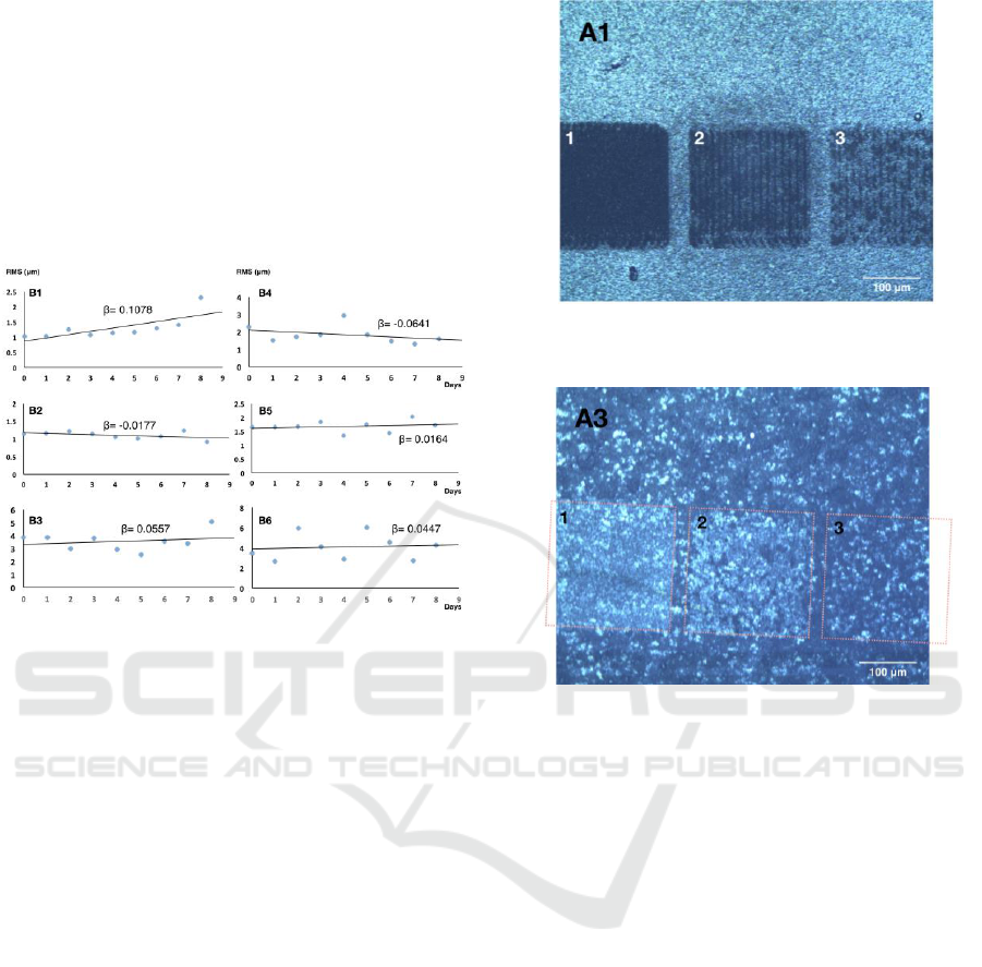
Figure 9: The roughness of different matting materials on
metal substrate varies with exposure time.
Figure 9 shows the roughness of different
matting materials on metal substrate varies with
exposure time. The surface of the sample B1 was
gradually roughened, which was completely
opposite to the case of the A1. This means that the
stability of the water-based black ink is not very
good. The sample B2 is still unaffected by the light
exposure and is the most stable material for anti-
photobleaching. Although sample B3 slowly
increase the roughness, it wasn't obvious. The result
was completely consistent with sample A3. The
results also show that the morphologies of the
sample B4, B5 and B6 are only slightly affected by
the water-based black ink. Their characteristics are
very similar to those of the B3. That is, the increase
and decrease in roughness are not significant. The
experimental results show that the matting materials
on the metal substrate have good anti-
photobleaching capacity, except for the water-based
black ink. Therefore, experimentally, it is necessary
to perform a longer light exposure or higher light
intensity to see an obvious difference in the anti-
photobleaching capacity of the matting material on
the metal substrate.
The matting materials in this experiment all have
good optical absorption characteristics, but the
Figure 10: Laser surface modification of the A1 matting
material.
Figure 11: Laser surface modification of the A3 matting
material.
scattering efficiency contribution of their surface
roughness is not actually significant. Then a 355 nm
pulsed laser was used to perform a surface
modification on them. The matting ability was
expected to be further increased. The experimental
results show two typical effects:First type is that
the surface modification of the sample generates a
highly scattering surface structure. The second type
is that the surface modification forms a photo
bleaching effect. Figures 10 and 11 show the
experimental results of surface modification
performed lasers on samples A1 and A3. Zone 1, 2
and 3 in Fig. 10 and 11 represent the morphology
and brightness of the sample processed by the laser
power of 3W, 1W and 0.5W, respectively. The
brightness change of the zones in image
demonstrates that different matting materials under
laser processing have two type results : Some
materials can increase their extinction by laser
modification, while the others only have the
opposite effect. It means that the laser surface
modification do not necessarily increase the
performance of the matting materials.
The Stray Light Absorption and Anti-photobleaching Capacity of Matting Materials on Optical System
63
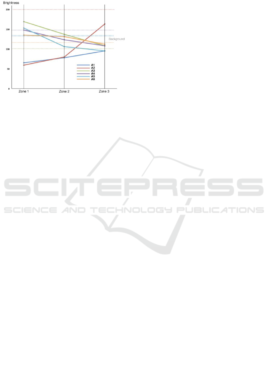
Figure 12: Reflected brightness change of the different
matting materials after laser surface modification.
Figure 12 shows the reflected brightness change
of the different matting materials after laser surface
modification. The horizontal axis is the surface
modification area under different laser powers. The
smaller the zone number, the greater the power. The
vertical axis is the relative brightness value. The
values are obtained by averaging the brightness in
the processing area. The dotted lines represent the
original brightness values of the matting samples.
They are relative reflectance before laser processing.
The experimental results show that both samples A1
and A2 become darker after laser treatment.
Conversely, the samples A3~6 become brighter. The
sample A2 has not only been demonstrated its ability
to resist photobleaching in previous experiments, but
also it has significantly increased its light extinction
capacity after laser surface modification. We can
therefore believe that it is the highest quality matting
material among these materials. This study proposes
a procedure for testing and analysing the matting
material quality. The performance of the materials in
optical absorption and anti-photobleaching could be
accordingly determined.
4 CONCLUSIONS
This study succeeded in developing a simple, rapid
and relative accurate method for the quality
estimation of the matting materials on glass and
metal substrate. A high intensity UV light source
with a wavelength of 365 nm was used to irradiate
the prepared matting materials for 8 days. With the
optical observation of experimental results, many
samples have the reflectance and morphology
changes. Roughness and brightness analysis allows
us to understand the anti-bleaching capacity of the
samples. The experimental results shows that the oil-
based matting paints and 1:1 mixed materials are the
most stable materials that have good anti-
photobleaching characteristic. A UV pulsed laser
was further used to try to improve the matting
performance of the materials. However, only some
materials can benefit from it. The other materials
have become less effective. This study procedure is
compatible with the other matting materials and can
be applied to various optical systems. This study
provides a useful database for optical matting and
anti-photobleaching technology.
ACKNOWLEDGEMENTS
The authors would like to express their appreciation
for financial aid from the Ministry of Science and
Technology, R.O.C under grant numbers MOST
107-2622-E-492-019-CC3. The authors would also
like to express their gratitude to the Instrument
Technology Research Center of National Applied
Research Laboratories for the support.
REFERENCES
Cheng, Y., Cheng D., Wang Y., 2018. “Design and stray
light analysis of a lenslet-array-based see-through
light-field near-eye display.” Digital Optics for
Immersive Displays. Vol. 10676. International Society
for Optics and Photonics.
Buisset, C., Prasita, A., Leckngama, A., Lépineb, T.,
Poshyajindaa, S., Soonthornthuma, B., Irawatia, P.,
Richichia, A., Sawangwita, U., Dhillonc,d, V., Hardy,
L. K., 2015, “Progress on the prevention of stray light
and diffraction effects on the Thai National
Telescope.” Optical Systems Design 2015: Optical
Design and Engineering VI. Vol. 9626. International
Society for Optics and Photonics.
Williams, E. A., Withington, S., Goldie, D. J., Thomas, C.
N., Chen, J., Ade, P. A. R., Sudiwala, R., Walker, I.
K., Trappe, N. A., 2018, “Ultra-low-noise transition
edge sensors for far infrared wavelengths: optical
design, measurement and stray light
control.” Millimeter, Submillimeter, and Far-Infrared
Detectors and Instrumentation for Astronomy IX. Vol.
10708. International Society for Optics and Photonics.
Patterson, B. A., Wells, M., 2003, “Analysis of scattered
light for VISTA.” Specialized Optical Developments
in Astronomy. Vol. 4842. International Society for
Optics and Photonics.
Benjamin, C., 1962, “Light loss and image formation in
optical systems, with special reference to endoscopic
instruments.” spiral.imperial.ac.uk.
PHOTOPTICS 2019 - 7th International Conference on Photonics, Optics and Laser Technology
64

Suzanna, A., Cohen, R., Magdassi, S., 2015, “Wet
deposition of carbon nanotube black coatings for stray
light reduction in optical systems.” Surface and
Coatings Technology, (262), 21-25.
Draggoo, V. G., Morton, R. G., Sawicki, R. H., Bissinger,
H. D., 1986, “Optical coating absorption measurement
for high power laser systems.” High power and solid
state lasers. Vol. 622. International Society for Optics
and Photonics.
Jürgen, I., 2008, “Micro patterning of fused silica by laser
ablation mediated by solid coating
absorption.” Applied Physics A, (93.1), 65-68.
Amemiya, K., Koshikawa, H., Yamaki, T., Maekawa, Y.,
Shitomi, H., Numata, T., Kinoshita, K., Tanabe, M.,
Fukuda, D., 2015, “Fabrication of hard-coated optical
absorbers with microstructured surfaces using etched
ion tracks: Toward broadband ultra-low
reflectance.” Nuclear Instruments and Methods in
Physics Research Section B: Beam Interactions with
Materials and Atoms, (356), 154-159.
Mohammad, A., Eslamimajd, A., Hajghassem, H., 2018,
“Stray light analysis, baffle, and optical design of a
high-resolution satellite camera.” Journal of Applied
Remote Sensing, 12(2), 026009.
The Stray Light Absorption and Anti-photobleaching Capacity of Matting Materials on Optical System
65
