
Detecting and Tracking Surgical Tools for Recognizing Phases of the
Awake Brain Tumor Removal Surgery
Hiroki Fujie
1
, Keiju Hirata
1
, Takahiro Horigome
1
, Hiroshi Nagahashi
2
, Jun Ohya
1
, Manabu Tamura
3
Ken Masamune
3
and Yoshihiro Muragaki
3
1
Department of Modern Mechanical Engineering, Waseda University, 3-4-1, Ookubo, Shinjuku-ku, Tokyo, Japan
2
Department of Mathematical and Physical Sciences, Japan Women’s University, 2-8-1, Mejirodai,
Bunkyo-ku, Tokyo, Japan
3
Faculty of Advanced Technology and Surgery, Tokyo Women’s Medical University, 8-1, kawada-cho,
Shinjuku-ku, Tokyo, Japan
Keywords: Computer Vision, Multiple Object Tracking, Detection, Data Association, Convolutional Neural Network,
Data Augmentation, Awake Brain Tumor Removal Surgery.
Abstract: In order to realize automatic recognition of surgical processes in surgical brain tumor removal using
microscopic camera, we propose a method of detecting and tracking surgical tools by video analysis. The
proposed method consists of a detection part and tracking part. In the detection part, object detection is
performed for each frame of surgery video, and the category and bounding box are acquired frame by frame.
The convolution layer strengthens the robustness using data augmentation (central cropping and random
erasing). The tracking part uses SORT, which predicts and updates the acquired bounding box corrected by
using Kalman Filter; next, the object ID is assigned to each corrected bounding box using the Hungarian
algorithm. The accuracy of our proposed method is very high as follows. As a result of experiments on spatial
detection. the mean average precision is 90.58%. the mean accuracy of frame label detection is 96.58%.
These results are very promising for surgical phase recognition.
1 INTRODUCTION
In modern operating rooms, the number of sensors
such as cameras has increased and the state of the art
medical instrument and equipment have been
introduced, which causes the advancement of
surgeries. The achievement of a system that
recognizes the situation in the operating room is
desired. Operation room monitoring system, staff
scheduling management etc are required as functions
of the surgical situation recognition system. As
another function, it is important to recognize surgical
phases such as what kind of actions and/or tasks the
doctors currently perform. This is needed for making
surgical work efficient. Many studies have been
conducted to recognize surgical phases based on
image information that can be obtained from cameras
used for the surgery.
The MICCAI 2016 Modeling and Monitoring of
Computer Assisted Interventions Workflow
Challenge in conjunction with the MICCAI
conference held a contest for surgical phase
recognition from videos acquired by a laparoscopic
camera in cholecystectomy surgery. This community
has started thinking the importance of automated
surgical phase recognition.
Various attempts have been made to recognize the
surgical workflows or phases by using various
information such as the signal of the binary
measurement device (Padoy et al., 2012), the RFID
tag (Bardram et al., 2011), the data acquired via
sensors of the tool tracking device (Holden et al.,
2014) and the survey robot (Lin et al., 2005).
However, since the amount of information obtained
from the surgery through the above-mentioned
sensors is huge, collecting these signals requires
almost manual annotation and installation of
additional equipment, which tends to increase in
unnecessary workloads.
Therefore, recent studies consider to identify
workflows based on video data collected during daily
surgical operations. However, it is very difficult to
automatically recognize the surgical phase from
video scene only. Therefore, in early studies, research
190
Fujie, H., Hirata, K., Horigome, T., Nagahashi, H., Ohya, J., Tamura, M., Masamune, K. and Muragaki, Y.
Detecting and Tracking Surgical Tools for Recognizing Phases of the Awake Brain Tumor Removal Surgery.
DOI: 10.5220/0007385701900199
In Proceedings of the 8th International Conference on Pattern Recognition Applications and Methods (ICPRAM 2019), pages 190-199
ISBN: 978-989-758-351-3
Copyright
c
2019 by SCITEPRESS – Science and Technology Publications, Lda. All rights reserved

to extract visual features manually from images was
conducted (Blum et al, 2010) (Lalys et al, 2012)
(Klank et al, 2008). Recently, with the development
of convolutional neural network (CNN), for various
image recognition tasks CNN is used. Studies using
CNN have also been proposed in the field of surgical
phase recognition (Twinanda et al, 2017). Many
studies based on CNN(Raju et al, 2016) (Sahu et al,
2016) use the data set of M2CAI tool to recognize
equipment and process at the frame level.
On the other hand, the surgical phase is a kind of
continuous function on time domain. Therefore, it is
essential to utilize temporal information for accurate
phase recognition so as to effectively extract
continuous dynamics. Specifically, surgical phase
recognition was achieved by Twinanda et al. They
constructed a 9-layer CNN for visual features and
designed a 2-level hierarchical HMM for modelling
temporal information (Twinanda et al, 2017).
Also, as a result of the development of a long-
short term memory (LSTM) network, it is possible to
model nonlinear dependence of long - range temporal
dependence. SV-RCNet (Jin et al, 2018), one of the
cutting-edge research on phase recognition of
surgical operations using LSTM, proposed to learn
both spatial (visual) information and temporal
information.
This paper aims at achieving automatic analysis
of surgical phases using intraoperative microscopic
video images as one of the operator supporting
functions of the project of the intelligent operating
room (SCOT) (Okamoto et al, 2017) for the awake
brain tumor removal surgery. This surgery removes
brain tumor, preserving maximal brain functions; for
this, the doctors communicate with awaking patients
during the surgery. Difficulties in this surgery are
caused by differences in individual patients’ brains.
As a result, the surgical phases becomes complicated;
therefore, only experienced doctors can perform this
surgery. It is difficult for surgical staffs other than the
experienced doctor to confirm the surgical situations
and predict the next surgical step; consequently, the
flow of the operation is stagnant. In order to solve
the above problems, phase recognition is also
required in surgical removal of waking brain tumor.
However, in brain tumor removal surgery, it is
difficult to recognize phases by frame-level
annotation like the conventional method. This is
because brain tumor removal surgery uses multiple
tools for each phase and the same tool, are also used
in different phases; namely, the phases and the tools
used do not have a one-to-one relationship.
Therefore, in the brain tumor removal surgery, in
order to recognize the phase, it is important to focus
on detailed information of the tool: specifically,
temporal motion information of the tool, the pose of
the tool, the type of the tool, and the like.
TSSD (Chen et al., 2018) is an object detection
method using spatial information and time series
information. However, it is not practical to perform
learning using both spatial and temporal information
like Chen et al.’s method, because an enormous
human annotation work is necessary for recognizing
phases of surgical operations. Therefore, in order to
use temporal information, this paper utilizes a fast
conventional tracking method and deep learning
method, but not LSTM.
2 DATA SET
None of data set for recognizing surgical tools of
awake brain tumor removal surgery has been
disclosed. Hence, We gave spatial annotation
(bounding box) to surgical tools in frames of videos
of actual awake brain tumor removal surgery
performed at Tokyo Women's Medical University
Hospital, and constructed a new data set that enables
higher level phase recognition.
Our dataset consists of 8 brain tumor removal
surgeries’ videos recorded at 30 fps. We pick up the
frames every 15 fps, randomly select 11175 frames
and labeled the 11175 frames with spatial bounding
boxes as tool candidates. The 11175 frames consist of
7755, 2270, 1150 frames for training, validation, and
test, respectively. The surgical tools included in the
data set are Bipolar, Electrode, Scissors, Suction tube,
Forceps, Clippers, which are mainly used for brain
tumor removal surgery. The number of annotated
instances per tool category is shown in Table 1.
Figure 1 shows an example of each tool in the data set.
The frequency of using surgical tools greatly varies
depending on tumor location, grade and so on.
Therefore, when learning is performed using n cross
validation method for each patient, bias could occur
in the current data set; therefore n closs validation is
not used in this paper.
Table 1: Number of annotated frames for each tool.
Tool
Number of annotated instance
Bipolar
5789
Electrode
2226
Scissors
1533
Suction tube
10207
Forceps
945
Clippers
896
Total
21596
Number of frame
11175
Detecting and Tracking Surgical Tools for Recognizing Phases of the Awake Brain Tumor Removal Surgery
191
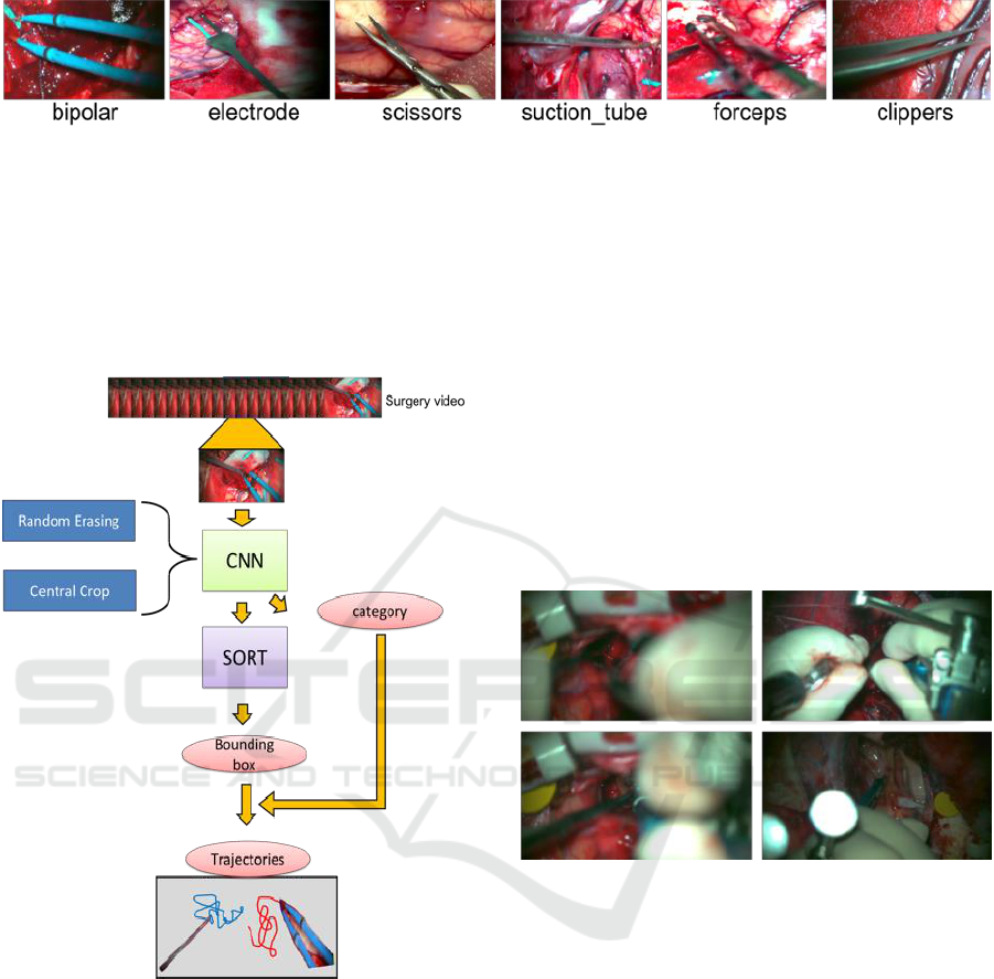
Figure 1: List of six surgical tools used in brain tumor removal surgery.
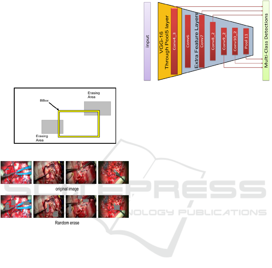
3 PROPOSED METHOD
The proposed method is composed of two parts: a
detection part and a tracking part. Figure 2 shows an
outline of the proposed method of this research.
Figure 2: Diagram of the proposed method.
3.1 Detection
Firstly extract the motion of a surgical tool, we detect
and classify the surgical tool. We can obtain a
candidate bounding box and its corresponding
category of the surgical tool as the output of applying
SSD (Liu et al, 2016) to a frame of the surgical video.
3.1.1 Data Augmentation
Here, before learning the data set, we execute data
augmentation to improve the robustness against
actual environmental changes that could occur at
surgical sites. We conduct central cropping and
random erasing (Zhong et al, 2017), and reinforced
our original data set. In addition to the data
augmentation originally provided by SSD, and
reinforced our data set.
3.1.2 Random Erasing
In actual surgery videos, there are frames in which
occlusions occur, and they make it difficult to detect
surgical tools accurately (Figure 3). The main reason
for the occurrence of occlusions is that the surgeon’s
hands appear between the microscope and the
surgical tool, or multiple tools overlap, etc.
Figure 3: Frame in which occlusion occurs.
In order to solve such a problem, we use random
erasing to improve robustness against the occlusions
in the data set and prevent over-fitting. Object
detection is important in this research. It is supposed
to detect instances of semantic objects of a particular
class in an image. Therefore, we use object-aware
random erasing. The width and height of image be W
× H (pixels) respectively. Thus, the region of the
image is S = W × H (pixels). The area of the erased
area is randomly initialized to
, where
is in
the range between the minimum sl and maximum sh.
The aspect ratio of the erased rectangular area is
randomly initialized to re between r1 and r2.
Parameters of the erasing area are sl=0.05, sh=0.1,
r1=3, r2 = 1/r1.
Here, let the coordinates bounding box of the top
left and the bottom right of the ground truth be (xmin,
ymin) and (xmax, ymax), respectively. Similarly, the
ICPRAM 2019 - 8th International Conference on Pattern Recognition Applications and Methods
192
coordinates of the erased area are expressed as (xe,
ye) (xe_max, ye_max). In this method, an erased area
is generated so as to satisfy the condition expressed
by Eqs. (1) and (2), rather than creating an erased area
in the bounding box of the ground truth.
xmin<xe_max xe < xmax
(1)
ymin<ye_max ye < ymax
(2)
A generation model diagram of the generated erased
area is shown in Figure 4, and an actual image is
shown in Figure 5.
Figure 4: Model of random erasing generation.
Figure 5: Example of applying random erasing to images.
The upper row is the original image which are cut out from
the surgical video. The lower row is an image in which
erased areas are generated for each original image.
3.1.3 Training
We use SSD for spatial detection of surgical tools.
SSD is one of the-state-of-arts of object detection
network. For the base network of SSD, we use VGG-
16 convolutional neural network (Simonyan et al,
2014), which extracts powerful visual features. The
base VGG-16 uses the model pre-trained and
initialized by ILSVRC CLS-LOC dataset
(Russakovsky et al, 2015), and we fine-tune the
model by Dataset that we created. The architecture of
SSD network is shown in Figure 6.
We finetune-tune the VGG-16 network and
optimize the performance of the model using
probabilistic gradient descent with initial learning
rates of
, 0.9 momentum, 0.0005 weight
decoy.
Figure 6: The architecture of SSD network.
3.2 Tracking
We track the surgical tools to detect how they are
moving. In this paper, we do not use a method that
requires large amounts of sequential time series data
such as LSTM. The reason is that it takes a huge
amount of human labor to build and self-tune our own
data set for a network that combines a region proposal
network such as SSD and LSTM.
Therefore, we use Alex's SORT (Bewley et al,
2016) which combines the famous Kalman Filter
(Kalman et al, 1960) and Hungarian algorithm (Kuhn,
1955) as one of the cutting-edge tracking methods for
real-time tracking.
3.2.1 Kalman Filter Estimation Model
The Kalman filter is one of the most stable filters that
can be estimated by predicting and updating the state
of the tracking object (Tracker). Here, the Kalman
filter is used to propagate the identity of the detected
bounding box to the next frame.
Since the predicted state of the current frame
is compared with that of the next frame, a better result
is obtained from the position of the detected object.
The displacement between each bounding box in
frames is approximated by a linear constant velocity
model, which is not related to the motion of other
objects and cameras. The state of each target is
modeled as follows.
(3)
where x and y are the center coordinates of each
bounding box, and scales s and r represent the scale
(area) and aspect ratio of the bounding box
respectively.
Detecting and Tracking Surgical Tools for Recognizing Phases of the Awake Brain Tumor Removal Surgery
193
3.2.2 Assign Detection and Tracker
In tracking multiple objects, the data assignment
process is needed. In our tracking system we use
Hungarian algorithm for data association.
Each detection is estimated by predicting a new
position by a Kalman filter (tracker). It is calculated
using the IOU matrix between the bounding box of
the tracker and the bounding box detected in the
current frame.
The minimum IOU (Intersection over union) is set
as the threshold value in order to reject the assignment
in which the overlap of each bounding box is less than
. In this paper,
= 0.3.
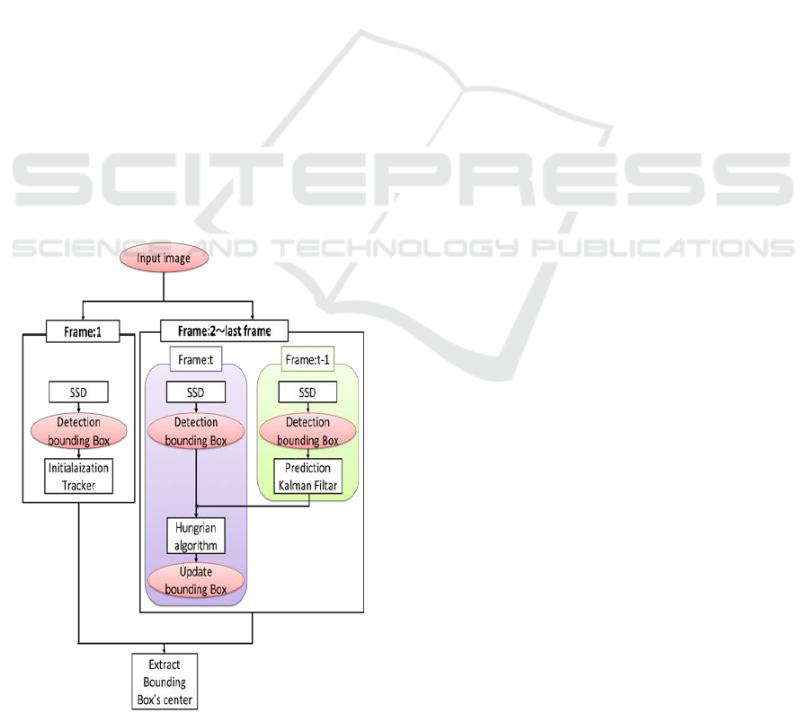
3.2.3 Tracking System
Figure 7 shows a detailed model of the tracking
system.
In order to do the tracking, the algorithm
initializes the tracker using only detected position
information in the first frame of the video. Next, from
the 2nd to final frames, a Kalman filter is applied to
the tracker of the (t-1)-th frame, to predict the t-th
frame, and the prediction of the t-th tracker is
matched with the t-th detection of the Hungarian
algorithm. By using the Hungarian algorithm, the
processing of the bounding box is classified into three
patterns shown below according to the relationship
between tracker and detection.
Figure 7: Our tracking system diagram.
(ⅰ) Matched
In this case, Both results from the tracker and the
detection match. The Kalman filter correction process
is performed to help the system model work better in
the next sequence.
(ⅱ) Unmatched detection
There is the tracker, but there is no corresponding
detection. In this case the tracker is removed. This is
mainly used when the object leaves the image and
deletes the ID unique to the object.
(ⅲ) Unmatched tracker
The detection exists, and there is no corresponding
tracker. In this case we create a tracker that
corresponds to the detection. This is mainly used
when an object enters the image and creates a unique
ID for the object.
By combining (ⅱ) and (ⅲ), in the tracking system,
the tracker is not deleted immediately after the tracker
is hidden, the tracker is deleted only when no tool is
detected in two consecutive frames, and the object ID
is assigned to the corresponding tracker. By
recognizing the object ID, it is considered that the
individual tool can be accurately identified and the
tracking can be performed more accurately.
4 EXPERIMENTS AND RESULTS
In this chapter, we evaluate the method of tracking
surgical tools using our data set we created. In the
detection section (Sec. 4.1) we quantitatively evaluate
the validity of our data augmentation, the task of
spatial detection and frame level presence detection
of surgical tools. In the tracking section (Sec. 4.2), we
evaluate the trajectory of each tool qualitatively.
Note that we have received approval by the ethics
review committee of Tokyo Women's Medical
University (1955-R2).
4.1 Detection
We use SSD for object detection. First of all, in order
to confirm the validity of data augmentation, all
layers of VGG-16 are fine-tuned for repeating 250 K
times with 8 mini batch sizes. The learning rate is
initialized to
, and it decreases by 10 times at
100K, 150K, 200K iterations. Total training time was
approximately 8 days on an NVIDIA GeForce
1080Ti. Finally, the parameters of the model in this
system were learned 150,000 times with batch size
ICPRAM 2019 - 8th International Conference on Pattern Recognition Applications and Methods
194

24. The learning rate is initialized to
, and it
decreases by 10 times at 100K iterations. Total
training time was approximately 10 days on an
NVIDIA GeForce 1080Ti.
4.1.1 Effectiveness of Data Augmentation
We verified the effectiveness of our data
augmentation method. The learning conditions are as
follows. ①Default: the data set described in Section
2. ②CCrop: central cropped data set. ③RE: random
erasing data set. Table 2 summarizes the conditions.
Table 2: Number of annotated frames for each tool.
condition
Train frames
Test frames
Default
7755
1150
CCrop
23418
3296
RE
31020
457
Default
First, we compare the results of testing under each
condition using default test data of our data set. Table
3 summarizes the results.
Table 3: vs Default Test each condition.
Tool
default
CCrop
RE
Bipolar
89.78
89.78
90.72
Electrode
99.38
94.81
99.66
Scissors
97.77
96.61
96.41
Suction tube
89.47
89.22
90.35
Forceps
86.78
85.59
90.11
Clippers
95.58
94.00
90.67
Mean AP
93.02
91.67
92.99
From Table 3, the mean AP (Average Precision)
for default is the most accurate. In case of central crop,
the average precision of all tools decreased. On the
other hand, random erasing reduced the mean AP by
0.02%, but this reduction is ignorable. In addition, for
all tools other than scissors and clippers, it can be seen
that the average precision of all have improved.
Central Crop
Next, we verify using the dataset to which the data
enlarged and cutted off by central crop are added. The
results are shown in Table 4.
As shown in Table 4, the accuracy is improved in
all the tools in the test data for CCrop, although the
improvement is very small. Therefore, performing the
central crop tends to be effective against the
environmental change due to the magnification
change of the microscopic image.
Table 4: vs Central Crop Test Data.
Tool
default
CCrop
Bipolar
90.60
90.64
Electrode
89.54
90.02
Scissors
90.54
90.72
Suction tube
89.49
90.13
Forceps
89.76
90.07
Clippers
89.95
90.30
Mean AP
89.98
90.32
On the other hand, as the reason why the
improvement in accuracy was insignificant is that the
ratio of cutting to the original image is [0.8, 0.9] this
time; it is considered that the image does not change
significantly and the accuracy does not improve.
Random Erasing
Finally, we verify test data with high occlusion
level(RE test in Table. 2 .) as shown in Figure 3. The
results are shown in Table 5. However, clippers are
excluded, because there was no scene in which the
clippers were hidden significantly in the surgery
video.
Table 5: vs Random Erasing Test Data.
Tool
Default
RE
Bipolar
89.86
89.70
Electrode
70.15
66.80
Scissors
46.56
69.35
Suction tube
80.00
84.00
Forceps
81.90
87.68
Clippers
Mean AP
73.69
79.51
From Table 5, accuracy improvement can be seen
in all the tools except Bipolar and Electrode, and the
average accuracy increased by 5.82%. In particular,
Scissors gained dramatically by about 23%. Figure 8
shows some results of detection using the weights of
Default and RE, respectively. (The visual-threshold is
the value of the score : 0.6.)
By doing RE we can successfully detect, classify
and localize surgical tools. Figure 8(a)-(c) show that
the detection is improved. In Figure 8(a), in the
Default, the suction tube existing in the upper left
cannot be detected, but it can be detected in the RE.
In Figure 8(b), the suction tube (the area surrounded
by the red color) existing in the upper left of both
Default and RE is detected as forceps. However,
when comparing the two, RE shows that the score of
forceps classification is lower. (Default: 0.97 > RE:
0.86). In Figure 8(c), two suction tubes overlap in the
lower right corner of the image. In Default it is found
that only one can be detected and bounding box is
Detecting and Tracking Surgical Tools for Recognizing Phases of the Awake Brain Tumor Removal Surgery
195
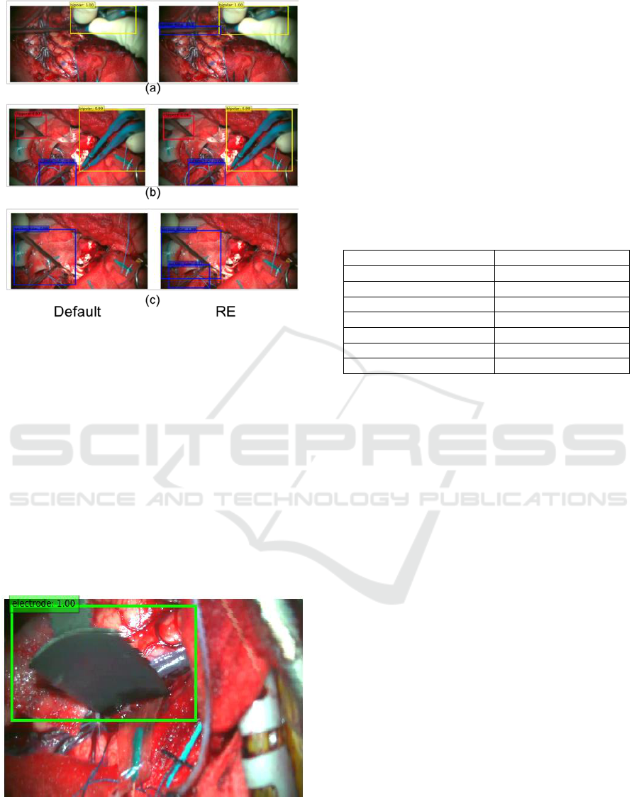
Figure 8: Example of detection result in frame where
occlusion occurs.(Left: Default weight, Right : RE weight).
redundant. In RE, two suction tubes can be detected
and bounding box can be localized more accurately.
However, for Electrode the score drops by 3.35%.
The reason for this is that the shapes of electrodes
excluding the tips and of the surgical tool called brain
spatula, which is not to be classified in this paper,
look very similar to each other. An example of
erroneously recognizing the brain spatula as electrode
is shown in Figure 9.
From the above result, it was found that random
erasing is very effective to the image data set acquired
from an environment like the awake brain tumor
removal surgery where occlusions frequently occcur.
Figure 9: Example of misrecognition that brain spatula as
electrode.
4.1.2 Spatial Detection
To the best of our knowledge, this study first
performed robust localization and classification
according to the actual environment of the surgical
tool with actual brain tumor removed video. We
analyze the movement of the surgical tools in more
detail.
Table 6 shows the performance when using the
average accuracy (AP) for spatial detection of the
surgical tool of brain tumor removal surgery in this
study.
Table 6: Spatial detection average precision (AP) per-class
and mean average precision (Mean AP) in All Dataset.
Tool
AP
Bipolar
90.71
Electrode
90.55
Scissors
90.74
Suction tube
90.18
Forceps
90.72
Clippers
90.57
Mean AP
90.58
Mean AP is 90.58, showing overall good performance.
Figure 10 shows some examples of detection results.
Images surrounded by a red thick frame are these that
can be detected correctly. It can be seen that,
irrespective of class and quantity, existing tools are
successfully detected. In addition, although two
suction tubes in the second row are overlapped, it can
be detected accurately. This also indicates that the
random erasing is effective. Next, the images
surrounded by the blue frame is an incorrectly
detected image. Figure 10(a) is a misdetection of
forceps as scissors. It is considered that this is due to
the similar shape of the tip portion. Figure 10(b)
bipolar appeared in the right part of the image is false
positive. Our system misunderstood that surgeon’s
left hand has the tool(bipolar). Figure 10(c) also
misrecognized bipolar as electrode. Figure 10(d)
shows that forceps existing right in the image is
unrecognized. Since we set visual threshold = 0.6 and
the value of confidence was less than the threshold,
the forceps couldn’t found. Overall our model has
strong accuracy in spatial detection.
4.1.3 Frame Level Presence Detection
Next, in this subsection we calculate the detection
accuracy at the frame level. We computed the
accuracy based on whether the visual threshold of the
detected object is greater than 0.6 for each frame.
The accuracy is shown in Table 7, and the confusion
matrix is shown in Table 8.
ICPRAM 2019 - 8th International Conference on Pattern Recognition Applications and Methods
196
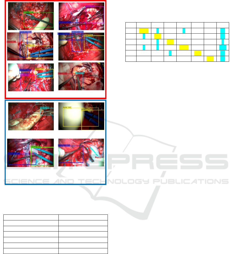
Figure 10: Example of detection result in frame.
Table 7: Flame label detection accuracy per-class and mean
accuracy in All Dataset.
Tool
Accuracy
Bipolar
98.19
Electrode
97.79
Scissors
97.79
Suction tube
94.85
Forceps
95.89
Clippers
94.98
From Table 7, we can see that the detection
accuracy by our approach demonstrates high
performance.
Empty cells in the confusion matrix in Table 8
shows that the value is 0. Yellow cells give correct
detections. False detections are indicated in blue. The
right most column named “RE” in the table indicates
reject, and it is a set of things which cannot be
detected and which are lower than the threshold in the
first place.
Table 8: Confusion matrix. (T0:Biolar, T1: Electrode, T2:
Scissors, T3: Suction tube, T4: Forceps, T5: Clippers, RE:
reject.).
T0
T1
T2
T3
T4
T5
RE
T0
1679
4
3
24
T1
1
620
13
T2
1
443
9
T3
2
2
2891
1
152
T4
1
303
11
T5
265
13
4.2 Tracking
In this section, we show that the bounding box
obtained from the model of the SSD that we have
metastasized and learned is stabilizing the locus
corrected by SORT. The method qualitatively
evaluates the trajectory of the center coordinates of
the bounding box by comparing it with the presence
or absence of SORT.
4.2.1 Detection and Tracker Assignment
The proposed method performs detector and tracker
assignment by using Hungarian method. In trajectory
extraction, this method can delete erroneous
detections and avoid unnecessary their assignment to
the tracker. An example of this deletion is shown in
Figure 11. In Figure 11, on the right side of Figure
11(a), multiple bounding boxes are detected at the tip
of the electrode. On the other hand, on the left Figure
11(a), using SORT, only one bounding box is
generated at the electrode, because a paint of
electrodes was not detected in the previous frame and
there is no corresponding tracker, the single bounding
box was deleted. For Figure 11(b) and Figure 11(c),
erroneous detection is also suppressed for the same
reason.
4.2.2 Trajectory
Figure 12. shows an example of trajectory extraction
using SORT. By using SORT, a smooth trajectory
compared with “not using SORT” is obtained. The
difference between with and without SORT can
clearly be demonstrated by movies, while not clear in
still images such as Figure 12.
10
Correct detections
Incorrect detections
(a) (b)
(c) (d)
Detecting and Tracking Surgical Tools for Recognizing Phases of the Awake Brain Tumor Removal Surgery
197
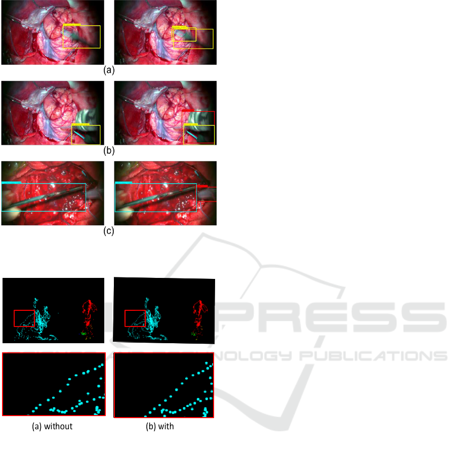
Figure 11: Delete detection with no corresponding
tracker.( Left: SORT, Right: without SORT).
Figure 12: Trajectory.
5 CONCLUSIONS
This paper has proposed a method for detecting and
tracking surgical tools from microscope video of
brain tumor removal surgery. The proposed method
consists of a detection part and tracking part. In the
detection part, object detection (SSD) is performed
for each frame in surgery video, and the category
(tool) and bounding box are acquired. The
convolution layer strengthens the robustness using
Data Augmentation. The tracking part uses SORT,
which predicts and updates the acquired bounding
box to which the object ID is assigned.
Experiments using 3751 frames is conducted.
Main results are as follows.
1. Spatial detection’s mean AP is 90.58%.
2. Frame label detection’s mean accuracy is
96.58%.
The future work of this research is as follows.
In order to deal with unrecognized result,
preprocess for CNN should be improved.
More advanced recognition system will be
studied which utilizes the content obtained from
the time series data trajectory and class
information of each tool.
Using RFID tags the classification accuracy will
be improved. We get information on the
currently used surgical tools. We can improve the
classification of actual surgical tools using
acquired sensor information. In particular , we
believe the above-mentioned method is effective
for detecting tools with similar appearances
(clipper, forceps, scissors).
Furthermore, we plan to conduct research to
identify the surgical phase.
REFERENCES
Bardram, J. E., Doryab, A., Jensen, R. M., Lange, P. M.,
Nielsen, K. L., and Petersen, S. T., 2011. Phase
recognition during surgical procedures using embedded
and body-worn sensors. In IEEE Int. Conf. Pervasive
Comput. Commun. (PerCom), 45–53.
Bewley, A., Ge, Z., Ott, L., Ramos, F. and Upcroft, B. 2016,
Simple online and realtime tracking, in 2016 IEEE
International Conference on Image Processing (ICIP),
3464–3468.
Blum, T., Feußner, H. and Navab, N., 2010, Modeling and
segmentation of surgical workflow from laparoscopic
video. in Proc. Int. Conf. Med. Image Comput.-Assist.
Intervent., 400–407.
Chen, X., Yu, J. and Wu., Z. 2018, Temporally Identity-
Aware SSD with Attentional LSTM. arXiv:
1803.00197.
Okamoto, J., Masamune, K., Iseki, H. and Muragaki, Y.
2017, Development concepts of a Smart Cyber
Operating Theater (SCOT) using ORiN technology.
Biomed Tech (Berl)., 63, 31-37.
Holden, M. S. et al., 2014. Feasibility of real-time workflow
segmentation for tracked needle interventions. IEEE
Trans. Biomed. Eng., 61(6), 1720–1728,.
Jin,Y. et al. 2018, SV-RCNet : workflow recognition from
surgical videos using recurrent convolutional network.
IEEE T-MI 37(5), 1114–1126
Kalman R. E. et al. 1960, A new approach to linear filtering
and prediction problems. Journal of basic Engineering,
82(1), 35–45.
Klank, U., Padoy, N., Feussner, H. and Navab, 2008, N.
Automatic feature generation in endoscopic images. Int.
ICPRAM 2019 - 8th International Conference on Pattern Recognition Applications and Methods
198

J. Comput. Assist. Radiol. Surgery, vol. 3(3–4), 331–
339.
Kuhn, H. W. 1955, The hungarian method for the
assignment problem, Naval research logistics
quarterly,2(1-2), 83–97.
Lalys, F., Riffaud, L., Bouget, D. and Jannin, P., 2012. A
framework for the recognition of high-level surgical
tasks from video images for cataract surgeries. IEEE
Trans. Biomed. Eng., 59(4), 966–976.
Lin, H. C., Shafran, I., Murphy, T. E., Okamura, A. M.,
Yuh, D. D. and Hager, G. D., 2005. Automatic
detection and segmentation of robot-assisted surgical
motions. in Proc. Int. Conf. Med. Image Comput.-
Assist. Intervent., 802–810.
Liu,W., Anguelov,D., Erhan, D., Szegedy, C., S. C., Reed,
Fu, Y. and Berg, A. C. 2016, SSD: Single shot multibox
detector. in Proc. Eur. Conf. Comput. Vis., Amsterdam,
Netherlands, 21–37.
Padoy, N., Blum, T., Ahmadi, S.-A., Feussner, H. , Berger,
M.-O. and Navab, N., 2012. Statistical modeling and
recognition of surgical workflow. Med. Image Anal.,
16(3), 632–641.
Raju, A., Wang, S. and Huang. J. 2016, M2CAI Surgical
Tool Detection Challenge Report.
Russakovsky, O., Deng, J., Su, H., Krause, J., Satheesh, S.,
Ma, S., Huang, Z., Karpathy, A., Khosla, A., Bernstein,
M., Berg, A.C., Fei-Fei, L. 2015, Imagenet large scale
visual recognition challenge. IJCV.
Sahu, M., Mukhopadhyay, A., Szengel, A. and Zachow, S.
2016, Tool and Phase recognition using contextual
CNN features. arXiv:1610.08854
Simonyan, K. and Zisserman., A. 2014, Very deep
convolutional networks for large-scale image
recognition. arXiv:1409.1556.
Tool Presence Detection Challenge Results. http:
//camma.u-strasbg.fr/m2cai2016/index.php/tool-
presence- detection-challenge-results.
Twinanda, A. P., Shehata, S., Mutter, D., Marescaux, J.,
Mathelin, M. de. and Padoy, N. 2017, Endonet: A deep
architecture for recognition tasks on laparoscopic
videos. IEEE Trans. Med. Imag., 36(1), 86–97.
Zhong, Z., Zheng, L., Kang, G., Li, S. and Yang, Y. 2017,
Random erasing data augmentation.
arXiv:1708.04896.
Detecting and Tracking Surgical Tools for Recognizing Phases of the Awake Brain Tumor Removal Surgery
199
