
A Digital in-line Holographic Microscope using Fresnel Zone Plate
Yonghao Liang, Yilei Hua
and Changqing Xie
Laboratory of Microelectronics Devices and Integrated Technology, Institute of Microelectronics,
Chinese Academy of Sciences, Beijing 100029, China
Keywords: Holography, Fresnel Zone Plate, Microscopy.
Abstract: A digital in-line holographic microscope is presented using Fresnel zone plate. The light impinging on the
Fresnel zone plate is divided into a number of diffraction orders. We use the 0rd light, which propagate
along the original direction, as the reference beam. And the first order focus is used as a virtual point source
after which the sample is placed. The light transmitted through the sample is scattered by the object and the
structure information is carried by the light. The interference fringes created by the first and zero order
diffraction are recorded by a digital camera. Afterwards, the object information is retrieved using
reconstruction algorithm. With the aid of the Fresnel zone plate, an image with higher lateral resolution and
lower noise could be obtained. This holographic microscope is tested with several samples and the results
show that the lateral resolution is good, and for the phase object, the measured phased difference is accurate
compared with the AFM test result.
1 INTRODUCTION
Digital in-line holographic microscopy (DIHM) is a
type of lensless Fourier transform digital
holographic, which the object light and reference
light are coaxial, interference pattern are recorded
digitally by CCD camera. (Depeursinge, 2011;
Kreuzer, 2007; Kreuzer, 2010) The amplitude and
phase distributions of the object are obtained by
simulating the reconstruction process numerically.
Compared with traditional microscopy, DIHM is
excellent in simple optical path, speed, real-time,
wide field, non-contact, and differential-
interference-contrast imaging etc. It is widely
applied to measure the three-dimensional shape of
the diffraction optical components, interference,
deformation, vibration, flow field and particle
tracking ,etc.
The most widely used the pinhole DIHM is
among the numerous methods. (Garcia-Sucerquia,
2006; Xu. 2002; Granero, 2011; Kuznetsova, 2007)
Its main factors affecting the imaging have the
following several aspects: the structure size and
shape of pinhole; area and pixel pitch of image
sensor; zero - order image and twin image. In
addition to select a more suitable sensor, composite
image is an effective way to expand the area through
nine images collected by moving CCD.
Twin image is another factor which affects the
performace of the DIHM. Many ways have been
proposed to reduce its effect on reconstructed image,
for instance, off-axis digital holographic, phase shift,
twice positions measurement etc. However, these
optical system or process of measurement is
complicated. So, we proposed a simple way, using
conventional diffraction optical element of Fresnel
zone plate (FZP) to solve this problem.
The FZP is laid behind the pinhole to separate
the point source into the 0th beam and the 1st beam.
The sample is put between the focus of the 1st beam
and the CCD along the optical axis. The interference
fringe pattern, formed by the two beams, is recorded
digitally by CCD. In a different way from point
diffraction interferometers, the interference fringe
pattern is a Fresnel hologram. A novel
reconstruction algorithm is proposed to present the
object image. Besides, it also has the following
advantages: the third problem proposed in previous
paragraph will be solved just through single
inversion; expands field of view, improves lateral
resolution, increases the space around sample plate
to be easy integrated.
Liang, Y., Hua, Y. and Xie, C.
A Digital in-line Holographic Microscope using Fresnel Zone Plate.
DOI: 10.5220/0007388802090212
In Proceedings of the 7th International Conference on Photonics, Optics and Laser Technology (PHOTOPTICS 2019), pages 209-212
ISBN: 978-989-758-364-3
Copyright
c
2019 by SCITEPRESS – Science and Technology Publications, Lda. All rights reserved
209
2 FZP DIHM CONFIGURATION
AND RECONSTRUCTION
ALGORITHM
2.1 DIHM Configuration
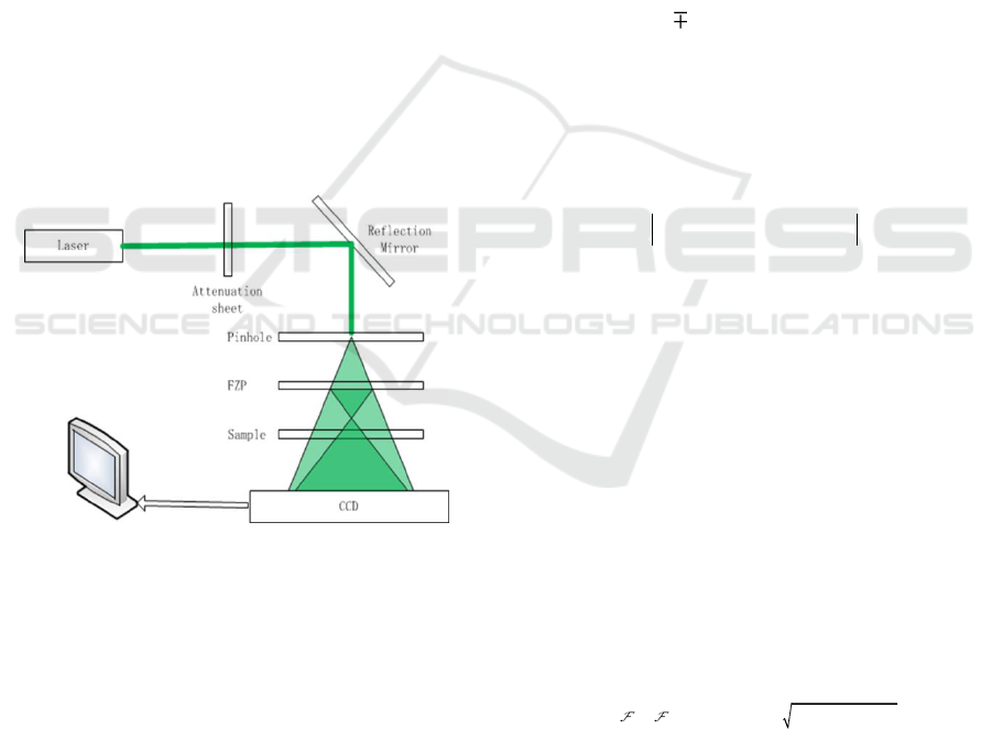
The configuration of the FZP DIHM is shown in
fig.1. The laser reaches pinhole through attenuation
sheet, reflection in turn. A spherical wave of
wavelength λ, emanating from the pinhole which is
regarded as the point source in pinhole DIHM,
illuminates an object. Without FZP, sample is
typically a distance of a few thousand wavelengths
from the source, and forms a highly magnified
diffraction pattern on a CCD much farther away.
The point source is major divided into 0rd scattered
spherical wave along the original direction and 1rd
gathered spherical wave by FZP. Sample is laid
behind the 1rd focus so that object information can
be scattered and form interference fringes with 0rd
reference beam. In order to satisfy the Nyquist
sampling criteria, CCD must be far away from
sample to ensure the finest interference fringe can be
digitally recorded by CCD.
Figure 1: The configuration of the FZP DIHM: laser is
focused onto pinhole after attenuation sheet and reflection
mirror. The emerging spherical wave is separated major
0rd scattering beam along the original direction as
reference light and the scattering object beam after 1rd
gathering. The interference pattern or hologram is
recorded digitally by CCD.
2.2 Interference Pattern
Ideally the reference wave emanating from the
pinhole is a spherical wave, irrelevant with FZP,
, where is the
wavenumber.
denotes the object beam, the
interference pattern as follows :
ref scat
**
ref scat ref scat ref scat
I A A
A A A A A A
2
22
( )=| ( )+ ( )|
=| ( )| +| ( )| + ( ) ( )+ ( ) ( )
r r r
r r r r r r
(1)
As Eq.1, the third term in the second line is the
holographic diffraction pattern in pinhole DIHM,
because it arises from the superposition of the
interference terms between the along the original
direction reference wave from point source and the
scattered wave from the object. The fourth term is
the conjugate function of previous term and also
contains the interference between the scattered
waves.
The structure of FZP can be expressed as a
coordinate transformation structure as follows
2
( , ) exp( )
FZP n
n
t r c jnar
(2)
0 1 2 3
1/ 2 1/ 0 1/ 3 ...c c c c
, , ,
.
Where,
The intensity of higher order diffraction is far
below 0rd and 1rd, moreover, 0rd is the reference
beam and 1rd is the object beam. So Eq.2 can be
simplified only including C
0
and C
1
. Then Eq.1 can
be rewritten as follows:
2
( ) exp( )/2 ( )/
scat
I j A
rr
(3)
It is obvious that first term in the second line is
constant, does not affect the results of the restoration
object. Second term is self-modulation image nearly
constant. According to third term, object information
can be acquired through reverse diffraction
transform. In regard to fourth term, the conjugate
image will appear if we do the forward diffraction
transform.
2.3 Reconstruction Algorithm
We use the angular spectrum method to reconstruct
the complex amplitude of the object. The O(x, y, 0)
stands for the optical field on the object plane and
O(x, y, z) stands for the optical field on the CCD
plane. The standard angular spectrum theory give us
2
2
1
( , ,0) ( , , ) exp 1
xy
O x y O x y z jkz f f
(4)
Where f
x
and f
y
are spatial frequencies.
For amplitude object, the structure can be
recovered by reckoning the amplitude. Phase object
must remove the phase envelope, because the
reference light is spherical wave, that the object
phase contains a phase envelope of a spherical wave
PHOTOPTICS 2019 - 7th International Conference on Photonics, Optics and Laser Technology
210
in general. Moreover, maybe there are some dirty
points on the CCD. Therefore, we use a symmetrical
hologram to restore the object. The equation is as
follows:
0
( , ) ( , ) ( , )I x y I x y I x y
(5)
The former is the hologram with object, the
latter not. Regardless of the type of object, light
changes only in the object exist. It is efficient to
recover the amplitude or phase object.。
3 EXPERIMENT RESULTS AND
DISCUSSION
In order to ensure good coherence on the surface of
CCD, 532nm laser is selected for illumination. After
all, green light is sensitive for our eyes and CCD.
CCD camera comes from Lumenera Company (pixel
pitch of 3.5um, 3000×2208 pixels, size of
10.5mm×7.7mm). The distance between CCD and
pinhole is 130±10mm (10mm is used to adjust Z
axis of CCD). The purpose of such a design is to
manufacture prototype consistent with the ordinary
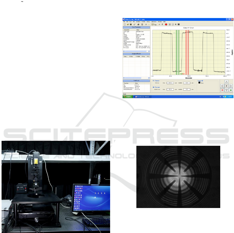
microscope in size. The experimental setup is shown
in fig.2.
Figure 2: The experimental setup.
One key feature of the DIHM is that it can detect the
transparent phase object. Phase object, which is
quite common in biological microscopy, does not
change the amplitude of the light, but change the
phase of the light. Many method, such as Zernike
phase contrast or differential interference contrast,
has been proposed. However, accurately measure the
phase change is still difficult.
To test the capability of our DIHM for phase
object detection, we fabricated a silica sample,
which is transparent, and with only steps on it, it is a
pure phase object. The steps are firstly measure by a
atomic force microscope (AFM), the test result is
shown in fig.3. According to the test result, the step
height is 111nm.
Figure 3: The profile of the silica sample with etched bars.
Then we use the DIHM to measure the height
of the bars. The hologram captured by CCD camera
is shown in fig.4. Auxiliary spokes is shown in the
hologram, for the bars in the center are relatively
small and difficult to find .
Figure 4: The hologram of the silica phase object.
After the hologram is recorded, we use the
numerical method discuss in section II to reconstruct
the profile of the bars. The reconstructed image is
shown in fig.5 , and the height of the step is also
shown, the result is 100nm, which is very close to
the result measured by AFM.
To verify the capability of our DIHM, many other
samples were observed using our experimental setup.
In fig.6, the wings of a fly and a bee is observed in
detail, the reconstructed image of the wings shows
that our DIHM can be applied to observe varies type
of samples.
A Digital in-line Holographic Microscope using Fresnel Zone Plate
211
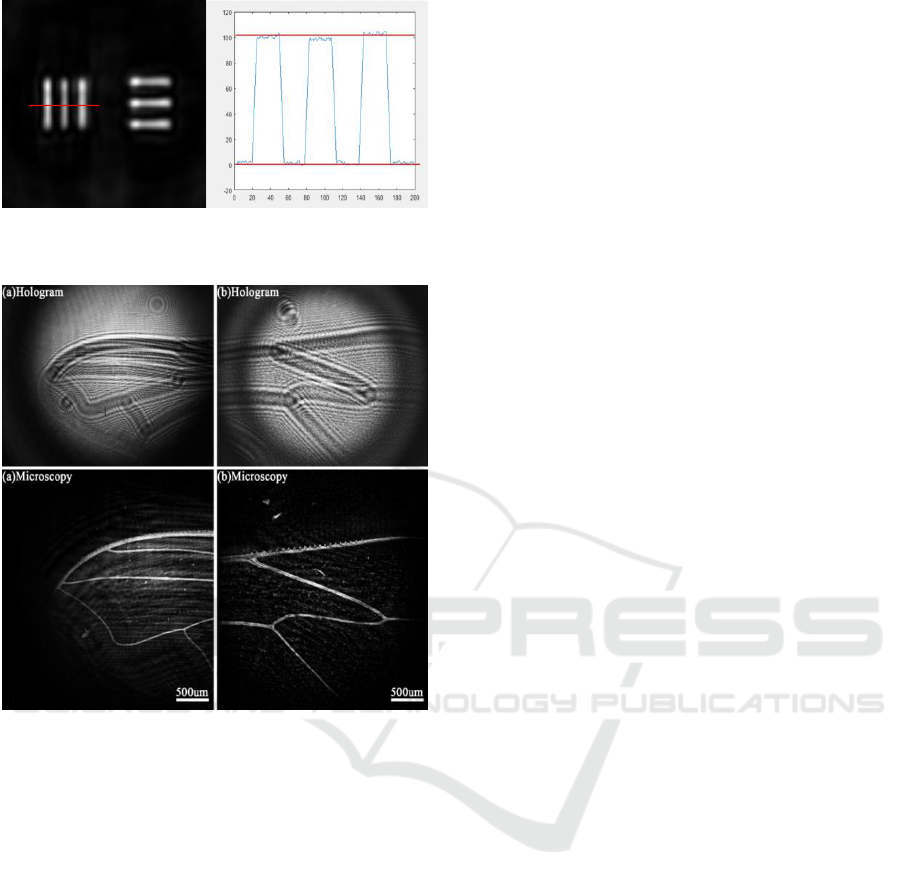
Figure 5: The reconstructed image of the bars and the
measured height.
Figure 6: The hologram and the reconstructed image of a
fly wing (a) and bee wing (b).
4 CONCLUSIONS
Digital in-line holographic microscopy using Fresnel
zone plate is a quick, large visual field and no
damage measurement method based on pinhole
DIHM. 0rd scattered spherical wave and 1rd object
spherical wave, emerging from FZP, form the
interference fringes on the surface of CCD. 1rd
spherical wave is gathered to a virtual point source,
and sample is putted behind the focus. So the
measurement object is easy to replace, because the
distance between FZP and sample is farther than
pinhole to sample in pinhole DIHM. Furthermore,
the field of view is expanded and the resolution is
improved.
Continuing to improve resolution of the
optical system, identification of interference fringes
must be promoted. Using a smaller pixel pitch CCD,
a shorter focal length FZP and composite picture
through moving the CCD to collect nine images are
efficient ways to make the resolution into Nano-
scale at present. Moreover, structured light may be a
way to increase contrast ratio between interfere
pattern and background and narrowband filter is
possible to remove unwanted lights.
The microscopy measurement system can be
used in detection of Micro / Nano element,
measurement and reconstruction of three-
dimensional shape of optical element, biological
recognition, path tracking of plankton etc.
ACKNOWLEDGEMENTS
This work was funded by National Key Research
and Development Program of China (Grant
No.2017YFA0206002)
REFERENCES
Depeursinge C, Moser C, Montfort F, et al. 2011 Dual
wavelength full field imaging in low coherence digital
holographic microscopy. Optics Express, , 19(24):
24005-22.
Kreuzer H J, Manfred J M H. 2007 Digital in-line
holographic microscopy. Imaging & Microscopy, 9(2):
63-5.
Kreuzer J, Jericho M H, Jericho S K. 2010, Digital In-Line
Holographic Microscopy in 4-D. Imaging &
Microscopy, 9(2): 63-5.
Garcia-Sucerquia J, Xu W, Jericho S K, Klages P, Jericho
M H and Kreuzer H J 2006 Digital in-line holographic
microscopy Appl. Opt. 45 836–50
Xu W, Jericho M H, Meinertzhagen I A and Kreuzer H J
2002 Digital in-line holography of microspheres Appl.
Opt. 41 5367–75
Granero L, Zalevsky Z and Micó V 2011 Single-exposure
twodimensional superresolution in digital holography
using a vertical cavity surface-emitting laser source
array Opt. Lett. 36 1149–51
Kuznetsova Y, Neumann A and Brueck S R 2007 Imaging
interferometric microscopy-approaching the linear
systems limits of optical resolution Opt. Express 15
6651–63
PHOTOPTICS 2019 - 7th International Conference on Photonics, Optics and Laser Technology
212
