
3D Cylinder Pose Estimation by Maximization of Binary Masks
Similarity: A simulation Study for Multispectral Endoscopy Image
Registration
O. Zenteno, S. Treuillet and Y. Lucas
PRISME, Univ. d’Orl
´
eans, F-45072 Orl
´
eans, France
Keywords:
Multispectral Endoscopy, Image Registration, Optical Biopsy.
Abstract:
In this paper we address the problem of simultaneous pose estimation for multi-modal registration of images
captured using a fiberscope (multispectral) inserted through the instrument channel of a commercial endoscope
(RGB). We developed a virtual frame using the homography-derived extrinsics parameters using a chessboard
pattern to estimate the initial pose of both cameras and simulate two types of fiberscope movements (i.e, inser-
tion and precession). The fiberscope pose is calculated by the maximization of similarity measures between
the 2D projection of the simulated fiberscope and the fiberscope tip segmentation from the endoscopic images.
We used the virtual frame to generate sets of synthetic fiberscope data at two different poses and compared
them after the maximization of similarity. The performance was assessed by measuring the reprojection error
of the control points for each pair of images and the pose absolute error in a sequential movement mimicking
scenario. The mean reprojection error was 0.38 ± 0.5 pixels and absolute error in the tracking scenario was
0.05 ± 0.07 mm.
1 INTRODUCTION
Gastrointestinal complications are usually produced
by a bacterial pathogen called Helicobacter pylori
(Hp). About 50% of the world’s population is infected
with Hp but most individuals remain asymptomatic
until developing clinical disease. The primary clinical
manifestations of the infection are chronic inflamma-
tion which produce cellular alterations of the gastric
mucosa (degeneration and infiltration) that can lead to
peptic ulcers and malignous complication.
Current early detection capabilities are primarily
based on gastro-endoscopic exploration under seda-
tion or anesthesia during which the clinician may per-
form a biopsy for further histopathological examina-
tion if needed. Some endoscopic systems propose
alternative spectral tools for helping gastric screen-
ing by the use of optical biopsies. Typical examples
are Fuji Intelligent Chromo Endoscopy (FICE), pro-
posed by Fuji and Narrow Band Imaging (NBI), pro-
posed by Olympus (Song et al., 2008). These techni-
ques have shown the benefits of using multiple wave-
lengths to improve the visibility of blood vessels and
other important features. However, they are limited
in the number of wavelengths processed. We believe
that using a larger number of bands in the visible and
near infrared (400-1000 nm) could improve characte-
rization of reflectance properties of the gastric mucosa
varying between healthy tissue and inflammatory or
malignant lesions.
For this purpose we developed a multispectral-
augmented endoscopic prototype illustrated on Figure
1. It is based on a Olympus (Tokyo, Japan) EVIS
EXERA III endoscopic system and a fiberscope (IT-
Concepts microflex m2.5-2500) is inserted into the
operators canal and connected to a multispectral ca-
mera. This allows simultaneous acquisition of white
light (WL) and a multispectral video (i.e., 41 spectral
bands in the range of 470 to 975 nm). This prototype
offers a familiar protocol for the clinician: he first
introduces the endoscope on the patient, then the fi-
berscope into the operator’s canal and performs the
simultaneous multi-modal exploration as with a con-
ventional endoscope. The multispectral probe works
as a localized optical biopsy for medical exploration
with a much smaller field of view.
There are several registration issues to overlay
both modalities (i.e., WL and multispectral): the two
images have different points of view, different reso-
lutions, different focal lengths and distortions. In ad-
dition, a conventional off-line static calibration using
a chessboard pattern can be used to estimate intrinsic
Zenteno, O., Treuillet, S. and Lucas, Y.
3D Cylinder Pose Estimation by Maximization of Binary Masks Similarity: A simulation Study for Multispectral Endoscopy Image Registration.
DOI: 10.5220/0007400808570864
In Proceedings of the 14th International Joint Conference on Computer Vision, Imaging and Computer Graphics Theory and Applications (VISIGRAPP 2019), pages 857-864
ISBN: 978-989-758-354-4
Copyright
c
2019 by SCITEPRESS – Science and Technology Publications, Lda. All rights reserved
857
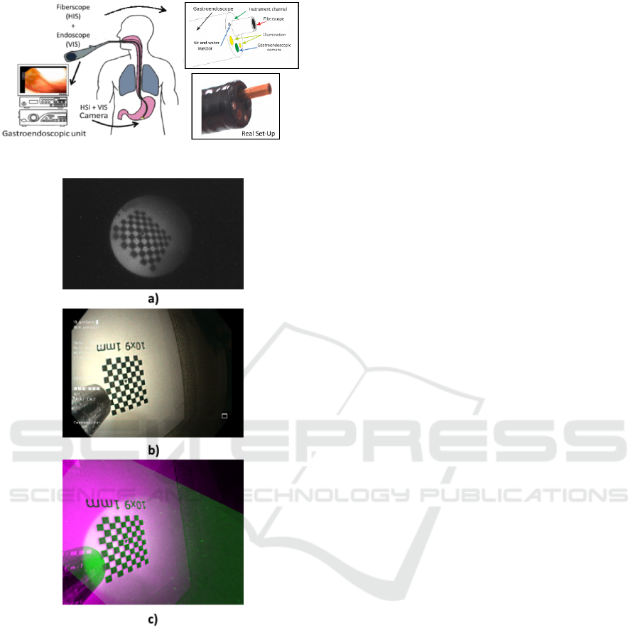
Figure 1: Augmented multispectral prototype.
Figure 2: a) Fiberscopic Image b) Endoscopic Image c)
Multimodal-enhanced image.
parameters of each cameras (focal length and distor-
tions) but the relation of both cameras cannot be con-
sidered rigidly fixed due to the fiberscope being re-
moved between patients for sterilization. Therefore, a
variation in the initial fiberscope insertion and a slight
bending of the fiberscope tip (precession) is always
present.
To perform the multimodal image registration du-
ring exploration we used the fiberscope’s tip, which
is always visible in the endoscopic image. A first ap-
proach was proposed in (Zenteno et al., 2018) ba-
sed on an off-line training with a chessboard pattern
of an adaptive affine transform. The transformation
compensates the zooming and decentering effect pro-
duced by the insertion/retraction movement of the fi-
berscope during in-vivo exploration. Although this is
really useful for insertion and retraction, it does not
take into account more complex movements which
can be induced by fiberscope manipulation like pre-
cession or axis displacement.
This paper presents a new approach based on a 3D
cylinder model of the fiberscope to achieve a more ro-
bust tracking of the tip’s pose and improve the image
registration accuracy. The remainder of this docu-
ment is organized as follow: Section 2 makes a re-
view of related works, Section 3 describes the met-
hod, Section 4 the results obtained and Sections 5
concludes the manuscript.
2 RELATED WORKS
The present multimodal image registration problem is
similar to the pose estimation of a tubular instrument
which is a classic issue of visual servoing for lapa-
roscopy and has been presented before in the litera-
ture. The application of artificial landmarks is a com-
mon practice as in (Kim et al., 2003) or (Tonet et al.,
2007). However, in the case of surgical instruments
with direct contact to human tissue, particular medi-
cal requirements such as the biocompatibility and the
sterilisability of the artificial markers have to be met.
(Doignon et al., 2008) presents several 3-D pose esti-
mation algorithms and visual servoing-based tracking
of tubular instruments with monocular vision systems
such as endoscopes and CT scanners. Another ap-
proaches using the video information provided by the
endoscopic camera have been proposed in (Cabras
et al., 2017) and (Reilink et al., 2013). The first relies
on colored markers attached onto the bending section.
The image of the instrument is segmented using a
graphbased method and the corners of the markers are
extracted by detecting the color transitions along Be-
zier curves fitted on edge points. The latter uses the
positions of three markers in the endoscopic image or
three feature points to update the state of a kinematic
model of the endoscopic instrument. However, these
existing solutions does not use multimodal images or
have been applied to ad-hoc laboratory setup which
cannot be directly used for real surgical systems. In
this paper, we propose a landmark-free approach to
dynamically estimate the pose changes between the
two cameras using only a binary segmentation of the
fiberscope tip in the endoscopic images, for a robust
real time image registration.
VISAPP 2019 - 14th International Conference on Computer Vision Theory and Applications
858
3 METHODOLOGY
3.1 Dual Camera Calibration
A set of chessboard pattern images is used to esti-
mate the intrinsic parameters and the distortion of
both cameras (endoscope and fibroscope). Calibra-
tion from real images of a chess-board pattern gi-
ves a realistic initial pose for the two cameras using
the homography-derived extrinsics parameters which
provide the translation vector T and rotation matrix R
relative to the world coordinates. The reference fra-
mes attached to each camera take the optical center C
for origin with its optical axis Z and the image plane
XY designated as C
z
and C
xy
respectively.
Figure 4 depicts the position of the three coordi-
nate reference frames used for the virtual modeliza-
tion:
- The world reference frame (W ) which origin is
at pattern’s left-top corner. W
xy
correspond to the
pattern horizontal and vertical dimension and W
z
is oriented on the acquisition system opposite di-
rection.
- The Fiberscopic reference frame (FC) which its
origin is at the end of the fibercope. FC
xy
and FC
z
correspond to the camera plane and its camera op-
tical axis respectively.
- The Endoscopic reference frame (EC) which its
origin is at the end of the endoscope. EC
xy
and
EC
z
correspond to the camera plane and its ca-
mera optical axis respectively.
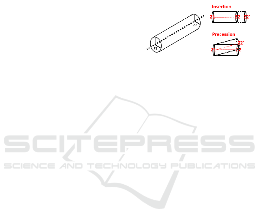
3.2 Fiberscope Model
The fiberscope is represented following its real geo-
metrical properties as a straight cylinder with a fixed
diameter of 2.5mm. The cylinder’s pose is defined by
two points: Z
1
and Z
2
, which are the two extremities
of its axis. The point Z
1
is fixed behind the initial FC
z
to be used as a pivot point. The point Z
2
is at the end
of the tip and it moves with the center of the camera.
We modeled two different movements: insertion
and precession (Fig 3). To model insertion the lo-
cation of Z
2
is translated along FC
z
according to the
desired depth and to model precession the position of
Z
2
moves in FC
xy
by two values (p
x
and p
y
). All coor-
dinate points are then transformed into FC.
The final extremity of the fiberscope’s tubular mo-
del (estimated camera location) is given by:
Z
2
= R
F
· [p
x
, p
y
, depth]
T
+ L
F
(1)
L
F
= −T
F
· R
F
T
(2)
where L
F
is the initial pose given by the initial cali-
bration (i.e, extrinsics parameters of fiberscopic ca-
meras).
Therefore the fiberscopic camera pose will be de-
fined by the vector [p
x
, p
y
, depth]
T
regarding FC.
Figure 3: Simulated fiberscope movements: insertion and
precession.
3.2.1 Image Projection
To simulate the observation of the fiberscope in the
endoscopic image the 3D cylindrical model is pro-
jected in 2D by using the projection matrix of the en-
doscopic camera defined as follow
m
E
= P · MP = K
E
1 0 0 0
0 1 0 0
0 0 1 0
[R
E
| T
E
] (3)
where
m
E
= Endoscopic 2D projection
P = Projection matrix
M = 3D point coordinates
K
E
= Endoscope calibration matrix
Figure 4 depicts the simulation interface where
the insertion depth, angles of precession of the fi-
berscope and rotation of the camera can be modified
interactively. The lower part presents: c) the cylin-
der model and virtual pattern projection superposed
to the original endoscopic image, d) the original fi-
berscopic image and e) the binary mask provided by
the projection of the world points in the 2D endosco-
pic plane.
3.3 Pose Estimation by Binary Mask
Similarity Maximization
The relative pose estimation between the two hetero-
geneous cameras (endoscopic/fiberscopic) is expres-
sed as a maximization problem by fitting the pro-
jection of the 3D cylinder into the fiberscope’s seg-
mented tip in the endoscopic image. To do this we
maximize a similarity measure between two binary
masks A and B.
3D Cylinder Pose Estimation by Maximization of Binary Masks Similarity: A simulation Study for Multispectral Endoscopy Image
Registration
859
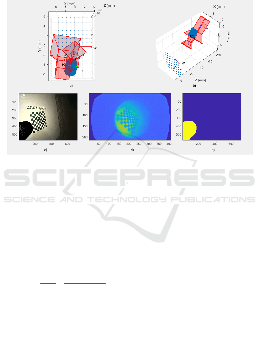
Figure 4: MATLAB simulator 3D view.
X = argmin[1 −S(A, B)] (4)
where X is the vector [p
x
,p
y
,depth]
T
representing the
pose of the cylinder’s extreme point.
3.4 Similarity Index
To compare the two binary masks we tested three
commonly used indexes (Csurka et al., 2013). All
similarity index S comply the condition 0 ≤ S ≤ 1
3.4.1 Jaccard
The Jaccard index J, also known as intersection over
union is defined as the size of the intersection divided
by the size of the union of the sample sets A and B. :
J(A, B) =
|A ∩ B|
|A ∪ B|
=
|A ∩ B|
|A| + |B| −|A ∩ B|
. (5)
3.4.2 Dice
Dice or Srensen’s measure it is defined as twice the
number of elements common to both sets divided by
the sum of the number of elements in each set.
DSC(A, B) =
2|A ∩ B|
|A| + |B|
(6)
where |A| and |B| are the cardinalities of the two
sets (i.e. the number of elements in each set).
3.4.3 BF-score
The BF score measures how close the predicted boun-
dary of an object matches the ground truth boundary.
It is defined as the harmonic mean of the precision
and recall values. Precision is the fraction of detecti-
ons that are true positives rather than false positives.
Recall is the fraction of true positives that are detected
rather than missed.
BF(A, B) = 2 ·
precision · recall
precision + recall
(7)
4 SIMULATION RESULTS AND
DISCUSSION
4.1 Objective Function
The behavior of the similarity indexes are observed
varying the three parameters of the fiberscope pose
(i.e., [p
x
,p
y
,depth]
T
) as shown in Figure 5.
Althought the BF-score behaves as a strongly con-
vex function while evaluating the two precession pa-
rameters, it lacks of singular minimum values when
analyzing the insertion parameter. Jaccard and Dice
behave similarly in the three cases, describing a sin-
gular min value in the exact fit case. However, Jac-
VISAPP 2019 - 14th International Conference on Computer Vision Theory and Applications
860
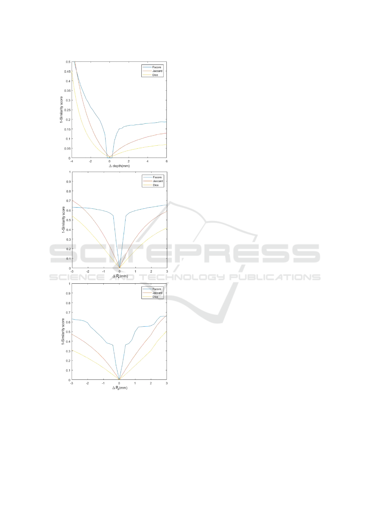
Figure 5: Behavior of objective functions.
card’s function presents itself as a better option due to
the higher value of its local tangents which may lead
to a faster convergence.
4.2 Convergence Validation
Twelve scenarios including highly ill-posed initiali-
zation were simulated. An example of four represen-
tative cases is presented in Figure 6. The first co-
lumn depicts the superposition of the initial and the
target segmentation. In the same manner, the second
column depicts the superposition of the final and the
target segmentation. In both cases yellow and green
represent the intersecting and individual pixels to the
two segmentations. The third column describes the
evolution of the three parameters estimates trough ite-
rations, the dotted lines represent the expected values
and the crosses the estimated values on each iteration.
Finally, the fourth column compare the corners loca-
tion of the virtual grids for estimated pose vs ground
truth pose.
Detailed results including the error statistics for
the projected points and a comparison between the
initial and final similarity measure for each case is
presented in Table 1. In addition a summary of sta-
tistics is presented in Table 1. The median error for
the sample set was 0.38 ± 0.5 pixels. We expected
the initial Jaccard similarity measure to be a determi-
nant for convergence. However, even when its value
is low (e.g., cases 5,6,7,9) the minimization can be
performed effectively. In contrast, we observed fai-
led convergences were more associated to inaccurate
final estimates (i.e.,Table 1). This may be related to
the fact that large variations in the optimized parame-
ters lead to small variation in the projected images due
to non-linearity included in the perspetive projection
4.3 Tracking Scenario
Figure 7 depicts the evolution of the estimated para-
meters trough a simulation of combined movements
of the tip during an exploration. From initialization,
the pose of the fiberscope is estimated frame by frame
by using the final estimate of the previous frame as
initial values for the current one. The trajectory was
determined by a combination of the parameters of in-
sertion and precession in an aleatory manner. The
overall mean absolute error in this measurements was
of 0.05 ± 0.07 mm. The number of iterations needed
for the initial fit was 75 and the number of iterations
needed for the following cases was 35 ± 5. Indeed,
the initial fit requires around the double of iterations
than the other points of the curve
We observe that in all cases the convergence was
achieved satisfactorily with high similarity measure
values and all differential errors being around zero.
This was expected due to the relative similarity bet-
ween successive frame. In addition, the convergence
3D Cylinder Pose Estimation by Maximization of Binary Masks Similarity: A simulation Study for Multispectral Endoscopy Image
Registration
861
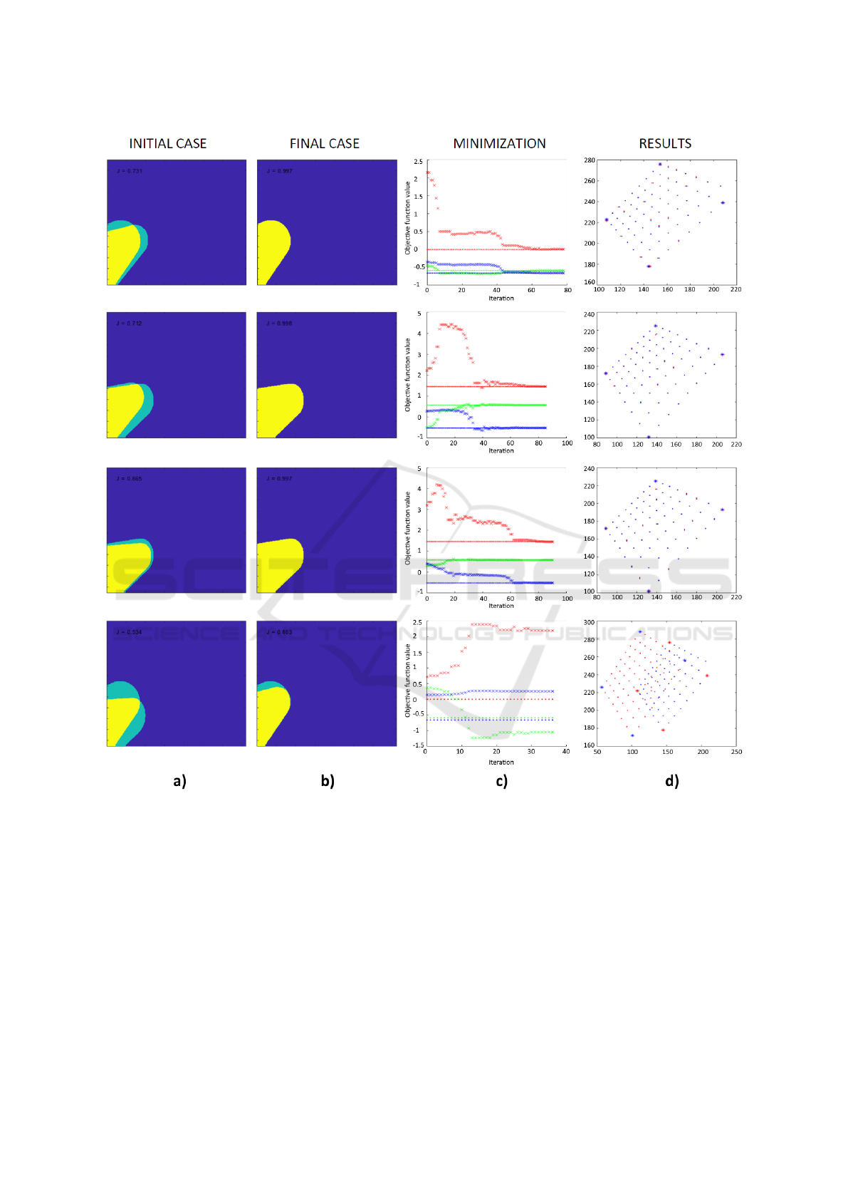
Figure 6: a) 2D projection of simulated sets before maximization, b) 2D projection of simulated sets after maximization, c)
Detail of the three objective function parameters over iteration time, d) reprojection results.
speed is also slower. So the minimization problem
could be critical for initialization in the first frame
only. However the approach presented in (Zenteno
et al., 2018) can provide a precise first initialization.
5 CONCLUSIONS
This paper has presented a method for simulating
and compensate two sources of movement encounte-
red during multi-spectral endoscopic acquisition for
multimodal registration (i.e, the insertion and preces-
sion motion of a fiberscope inserted in the instrument
channel of an endoscope). The technique relies on ap-
plying an homographic transformation between mo-
dalities by using a virtual reference pattern projected
in both frames as control points. The results showed
that the method can track the camera insertion and
precession motion. Although the pipeline is still cur-
rently executed off-line, this paper demonstrates the
potential of image-based tracking of a fiberscope.
VISAPP 2019 - 14th International Conference on Computer Vision Theory and Applications
862
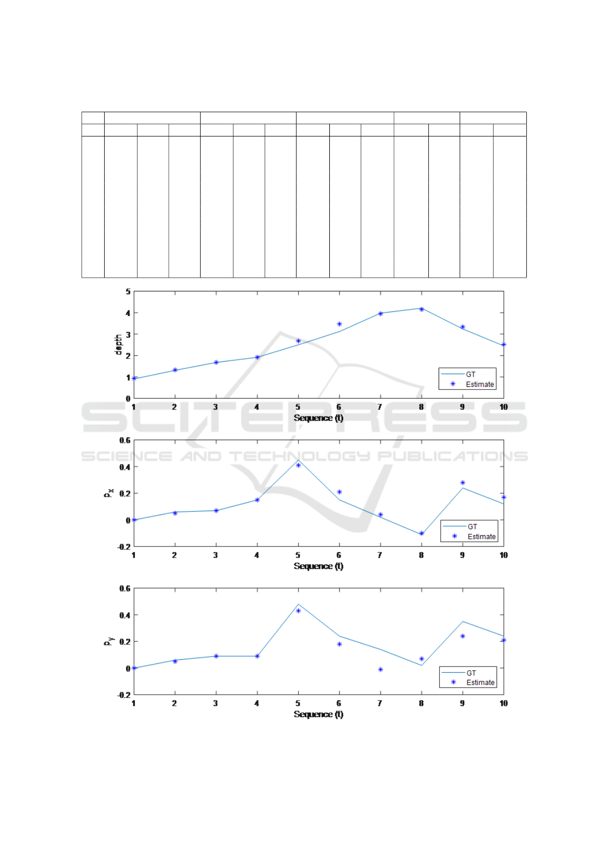
Table 1: Similarity measure comparison and projection error statistics.
Target pose (mm) Initial pose (mm) Estimated pose (mm) Jaccard E
Reprojection
No depth p
x
p
y
depth p
x
p
y
depth p
x
p
y
Initial Final Mean STD
1 3.17 0.00 0.00 1.62 0.00 0.00 3.177 -0.00 0.00 0.93 0.99 0.25 0.50
2 3.17 0.00 0.00 4.20 0.00 0.00 3.18 0.00 0.01 0.97 0.99 0.00 0.00
3 3.17 0.00 0.00 3.55 -0.21 -0.31 3.16 0.00 -0.00 0.87 0.99 0.00 0.00
4 3.17 0.00 0.00 3.55 0.64 0.29 4.29 -0.08 0.37 0.77 0.96 14.53 7.55
5 0.00 -0.59 -0.66 2.15 -0.44 -0.35 0.00 -0.59 -0.66 0.71 0.99 0.00 0.00
6 1.45 0.57 -0.52 2.21 -0.50 0.28 1.45 0.57 -0.52 0.86 0.99 0.25 0.50
7 1.45 0.57 -0.52 3.19 0.30 0.39 1.44 0.56 -0.52 0.53 0.88 43.87 6.10
8 0.00 -0.59 -0.66 0.71 0.37 0.13 2.19 -1.05 0.25 0.73 0.99 0.50 0.58
9 1.85 -0.59 0.66 2.21 0.36 -0.31 1.86 -0.58 0.66 0.68 0.99 0.25 0.50
10 1.85 -0.59 0.66 2.99 0.36 0.77 4.64 -0.99 1.74 0.66 0.92 39.52 17.68
11 2.34 0.00 0.00 2.41 -0.21 -0.16 2.22 0.03 -0.04 0.89 0.99 1.97 0.39
12 1.37 0.00 0.00 6.48 0.00 0.00 1.38 0.00 0.00 0.85 0.99 0.75 0.50
Figure 7: Comparison of estimated values versus ground truth along a 10 step sequential movement mimicking scenario.
3D Cylinder Pose Estimation by Maximization of Binary Masks Similarity: A simulation Study for Multispectral Endoscopy Image
Registration
863

ACKNOWLEDGEMENTS
This work was supported by the EMMIE (Endosco-
pie MultiModale pour les l
´
esions Inflammatoires de
l’Estomac) project funded by the ANR-15-CE17-
0015 grant.
REFERENCES
Cabras, P., Nageotte, F., Zanne, P., and Doignon, C. (2017).
An adaptive and fully automatic method for estima-
ting the 3d position of bendable instruments using
endoscopic images. The International Journal of
Medical Robotics and Computer Assisted Surgery,
13(4):e1812.
Csurka, G., Larlus, D., Perronnin, F., and Meylan, F. (2013).
What is a good evaluation measure for semantic seg-
mentation?. In BMVC, volume 27, page 2013. Cite-
seer.
Doignon, C., Nageotte, F., Maurin, B., and Krupa, A.
(2008). Pose estimation and feature tracking for robot
assisted surgery with medical imaging. In Unifying
perspectives in computational and robot vision, pages
79–101. Springer.
Kim, M., Lee, J., and Huh, J. (2003). Real time visual
servoing for laparoscopic surgery. In lnternational
Symposium on Artificial Life and Robotics, pages 0–
0. ISALR.
Reilink, R., Stramigioli, S., and Misra, S. (2013). 3d po-
sition estimation of flexible instruments: marker-less
and marker-based methods. International journal of
computer assisted radiology and surgery, 8(3):407–
417.
Song, L. M. W. K., Adler, D. G., Conway, J. D., Diehl,
D. L., Farraye, F. A., Kantsevoy, S. V., Kwon, R., Ma-
mula, P., Rodriguez, B., Shah, R. J., et al. (2008). Nar-
row band imaging and multiband imaging. Gastroin-
testinal endoscopy, 67(4):581–589.
Tonet, O., Thoranaghatte, R. U., Megali, G., and Dario, P.
(2007). Tracking endoscopic instruments without a
localizer: a shape-analysis-based approach. Computer
Aided Surgery, 12(1):35–42.
Zenteno, O., Krebs, A., Treuillet, S., Lucas, Y., Benezeth,
Y., and Marzani, F. (2018). Dual-channel geometric
registration of a multispectral-augmented endoscopic
prototype. In VISIGRAPP (4: VISAPP), pages 75–82.
VISAPP 2019 - 14th International Conference on Computer Vision Theory and Applications
864
