Subpixel Unsynchronized Unstructured Light
Chaima El Asmi and Sébastien Roy
Département d’Informatique et de Recherche Opérationnelle, Université de Montréal, Montréal (Québec), Canada
Keywords:
Computer Vision, Active Reconstruction, Unstructured Light, Unsynchronized Camera-Projector Systems,
Subpixel Accuracy, 3D Scanning.
Abstract:
This paper proposes to add subpixel accuracy to the unsynchronized unstructured light method while achieving
high-speed dense reconstruction without any camera-projector synchronization. This allows scanning faces
which is notoriously difficult due to involuntary movements on the part of the model and the reduced
possibilities of 3D scanner approaches such as laser scanners because of speed or eye protection. The
unsynchronized unstructured light method achieves this with low-cost hardware and at a high capture and
projection frame rate (up to 60 fps). The proposed approach proceeds by complementing a discrete binary
coded match with a continuous interpolated code which is matched to subpixel precision. This subpixel
matching can even correct for erroneous camera-projector correspondences. The obtained results show that
highly accurate unfiltered 3D models can be reconstructed even in difficult capture conditions such as indirect
illumination, scene discontinuities, or low hardware quality.
1 INTRODUCTION
The subpixel correspondence is very important in 3D
reconstruction as it enables a smooth and dense 3D
model. Generally, active reconstruction produces a
correspondence where one camera pixel corresponds
to one particular projector pixel. On the other hand,
by achieving a subpixel correspondence, the accuracy
is greatly improved as it improves the matches and
enables pixels to be matched to a fractional part of
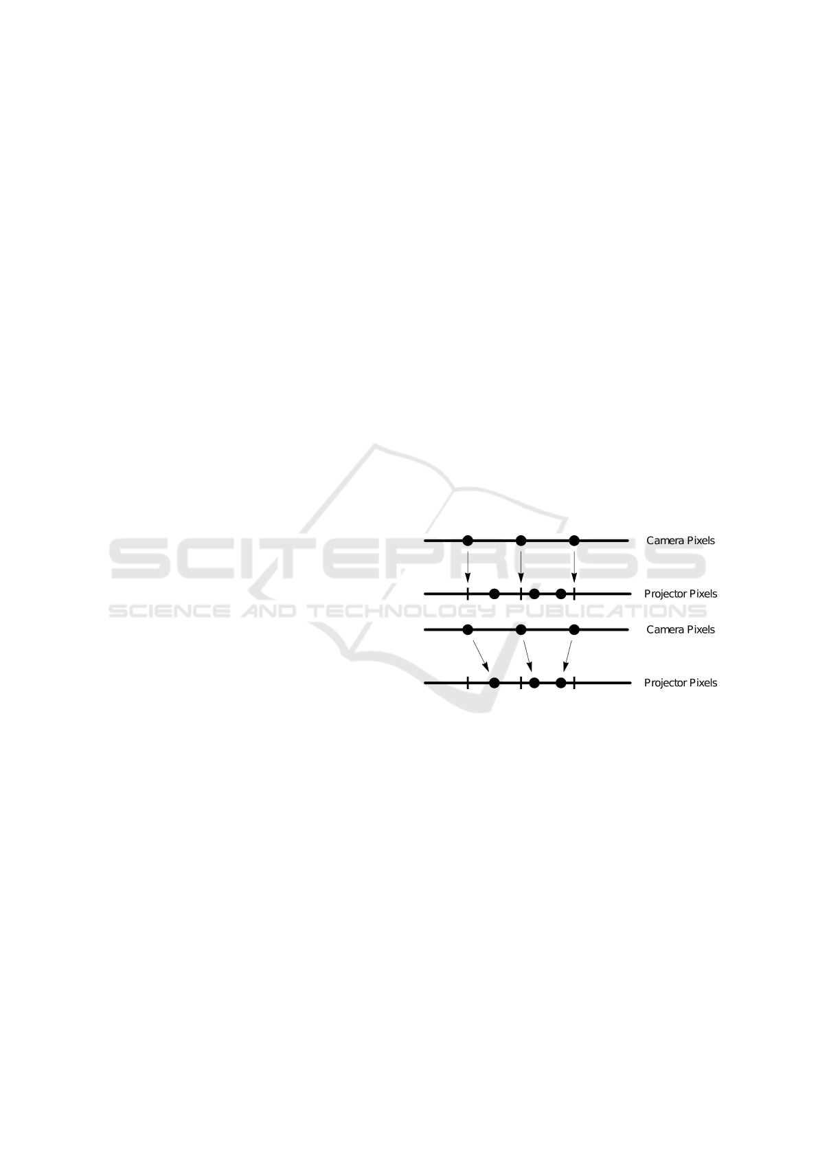
another pixel, as illustrated in Fig. 1.
There are multiple active reconstruction methods
that can provide a subpixel correspondence. These
methods are divided into two broad categories which
can further be split into multiple methods. These
methods are referred to as the structured light method
and the unstructured light method. The first category
consists of projecting several structured light patterns
and directly encoding the position of the projector
pixel. In this category, the first method is the
Gray Code (Inokuchi, 1984) and the patterns are
composed of white and black stripes at different
frequencies. A second method is the Phase Shift
(Srinivasan et al., 1984) where sinusoidal patterns,
composed of the same sine shifted several times at
different frequencies, are projected. These methods
exhibit many difficulties in scene discontinuities and
they are not robust to indirect illumination which
in turn leads to multiple matching errors. Several
Figure 1: Obtained pixel correspondence between the
camera and the projector (top) and a pixel correspondence
with subpixel accuracy between the camera and the
projector (bottom). This means a pixel can be matched to
a fractional part of another pixel. The notches represent
the integer position of the corresponding pixels and the dots
represent their true position.
other approaches have tried to improve the Phase
Shift (Chen et al., 2008; Gupta and Nayar, 2012;
Gu et al., 2011). These methods will be detailed
in the next section. The second category, unlike
the previous one, consists in encoding the position
of the projector and the camera in a LookUp-Table
(LUT) (Kushnir and Kiryati, 2007; Wexler et al.,
2003; Couture et al., 2014). The unstructured light
method provides bidirectional matching (from camera
to projector and from projector to camera). In
(Couture et al., 2011), they improved the patterns by
generating sines in random directions in the frequency
El Asmi, C. and Roy, S.
Subpixel Unsynchronized Unstructured Light.
DOI: 10.5220/0007404608650875
In Proceedings of the 14th International Joint Conference on Computer Vision, Imaging and Computer Graphics Theory and Applications (VISIGRAPP 2019), pages 865-875
ISBN: 978-989-758-354-4
Copyright
c
2019 by SCITEPRESS – Science and Technology Publications, Lda. All rights reserved
865

domain. Additionally, these patterns don’t feature
large black and white regions. For this reason, this
method is very robust to indirect illumination and
scene discontinuities.
The methods presented above must synchronize
their projectors and their cameras. Without
synchronization, the camera sees mixed projected
patterns which results in wrong correspondences. To
obtain a correspondence from patterns projected in
time, the camera must see each projected pattern
by the projector only once. There are two types
of synchronization; hardware synchronization (Takei
et al., 2007; Zhang et al., 2010; Rusinkiewicz et al.,
2002; Liu et al., 2010; Wang et al., 2011) and
software synchronization (Herakleous and Poullis,
2014; Koninckx and Van Gool, 2006; Jaeggli
et al., 2003). The first type requires expensive and
experimental equipment. It consists in synchronizing
the projector and the camera using a triggering
circuit (Liu et al., 2010; Wang et al., 2011). This
type of synchronization allows the capture of image
sequences at very high frame rate (up to 3000 fps
(Takei et al., 2007)). The second type does not require
any experimental material. It is a structured light
scan at very low frame rate (usually less than 5 fps).
Unfortunately, this method, with its low frame rate,
requires a large amount of time for the camera to fully
capture the projected patterns exactly once.
Other methods have performed unsynchronized
coded light scans (Sagawa et al., 2014; Moreno et al.,
2015; El Asmi and Roy, 2018). The difficulties of
the unsynchronized capture reside in finding the first
image in the captured sequence and in finding the
mixture between two consecutive patterns partially
seen by the camera as a single image. Indeed, during
the unsynchronized capture at very high frame rate,
the camera sees a mixture of two consecutive patterns.
It then becomes impossible to get a correspondence
between the camera and the projector.
The first method (Moreno et al., 2015) consists in
projecting structured light patterns at a high frame
rate without synchronization between the projector
and the camera. The authors project a looping video
of structured light patterns. In order to detect the first
image in the captured sequence, they project an easily
identifiable sequence of entirely black and entirely
white patterns at the beginning of the sequence.
They then generate an image formation model of
the camera in order to find the synchronization
parameters and to recover the patterns corresponding
to the Gray Code. This method requires complex
and very long computations in order to solve the
equation systems of the image model. In addition,
it is not robust to indirect illumination and scene
discontinuities due to the use of Gray Code.
Alternative method (El Asmi and Roy, 2018)
solved the synchronization problem by projecting
a looping video of unstructured light patterns at a
high frame rate (30 to 60 fps). The camera starts
capturing at any time. Thus, it is necessary to find
the first image of the captured sequence. They do
so by making several correspondences between the
captured sequence and the reference sequence which
is shifted by one pattern at each correspondence.
The first image in the captured sequence is found
using the best correspondence after calculating the
matching costs. They then find the mixture between
the two consecutive patterns by mixing them. The
unstructured light patterns are generated randomly
so mixing them gives a new random pattern. This
method is very fast and simple. It can scan in less
than two seconds at 30 or 60 fps. However, this
method does not achieve a correspondence with a
high subpixel accuracy. In this paper, we describe
a new technique to improve the unsynchronized
unstructured light method by matching with a high
precision subpixel.
2 PREVIOUS WORK
There are several active methods that achieve a
high precision subpixel correspondence. In articles
(Salvi et al., 2004; Salvi et al., 2010), a survey
on structured light methods is presented. In
general, methods that achieve subpixel precision
are based on sinusoidal patterns (Wust and Capson,
1991; Zhang and Yau, 2007). The patterns are
composed of multiple sines each shifted by a different
amount in a given direction and with different
frequencies. The sines vary from a very low
frequency to a very high frequency. Thus, each
camera pixel encodes the projector position directly
by a unique phase. This method achieves a dense
reconstruction with a high subpixel accuracy through
the different gray intensities. However, this method
requires photometric calibration because the phase is
recovered from the pixel intensities. Furthermore, it is
not robust to the indirect illumination which is caused
by the low frequency patterns.
In (Chen et al., 2008), they improved the projected
patterns by modulating a high frequency signal, so
that they are robust to indirect illumination and
achieve a high subpixel accuracy. Modulated Phase
Shift patterns are composed of modulated sines in
both directions (two-dimensional patterns) at a very
high frequency. Unfortunately, this method requires
a very high number of patterns. In (Gu et al.,
VISAPP 2019 - 14th International Conference on Computer Vision Theory and Applications
866
2011)’s method, they reduced the number of patterns
by multiplexing the modulated patterns together.
These three methods require what is called the phase
unwrapping because of the periodic nature of patterns
(Huntley and Saldner, 1993; Nayar et al., 2006).
Indeed, we must be able to differentiate between
the different phases of each period. Micro Phase
Shift method (Gupta and Nayar, 2012) resolves the
problem of phase unwrapping by projecting only a
high frequency patterns. Alternative methods have
used the Gray Code (Gühring, 2000) to achieve
a subpixel reconstruction. Line Shifting (Gühring,
2000) evaluates the subpixel only in the bit transitions
(0 to 1 or 1 to 0). However, these alternative methods
result in a sparse reconstruction.
In (Martin et al., 2013), they use the unstructured
light method to achieve the subpixel accuracy.
This method is very robust to indirect illumination
and scene discontinuities through their gray level
band-pass white noise patterns. They project a lower
number of patterns than the method in (Couture
et al., 2011). They also improved their technique
to generate the codewords (Salvi et al., 2004).
By comparing two neighboring codewords, they
determine the region where the subpixel is located.
They then divide it into four bins by interpolating
between the four pixels that define this region. They
additionally make a hierarchical vote to choose the
right bin and further divide it into another four bins.
This operation is repeated recursively several times
until they obtain the desired amount of subpixel
precision. This method requires a huge calculation
time because of the recursion and the hierarchical
vote. In this paper, the unsynchronized unstructured
light method (El Asmi and Roy, 2018) is improved
by accomplishing a high subpixel accuracy. A simple
and fast technique to determine the subpixel position
is presented in Sec. 4.
3 RELEVANT SUBPIXEL
INFORMATION
In establishing pixel correspondence with
unstructured light patterns, several parameters
have an impact on subpixel accuracy. Amongst these
parameters, there is the pattern frequency and the
pixel ratio as well as the code-length (linear and
quadratic code). Modulating these parameters allow
the subpixel accuracy to either improve or degrade.
-300 -200 -100 100 200 300
pixels
50
100
150
200
250
cost
(a)
-300 -200 -100 100 200 300
pixels
50
100
150
200
250
cost
(b)
-300 -200 -100 100 200 300
pixels
50
100
150
200
250
300
cost
(c)
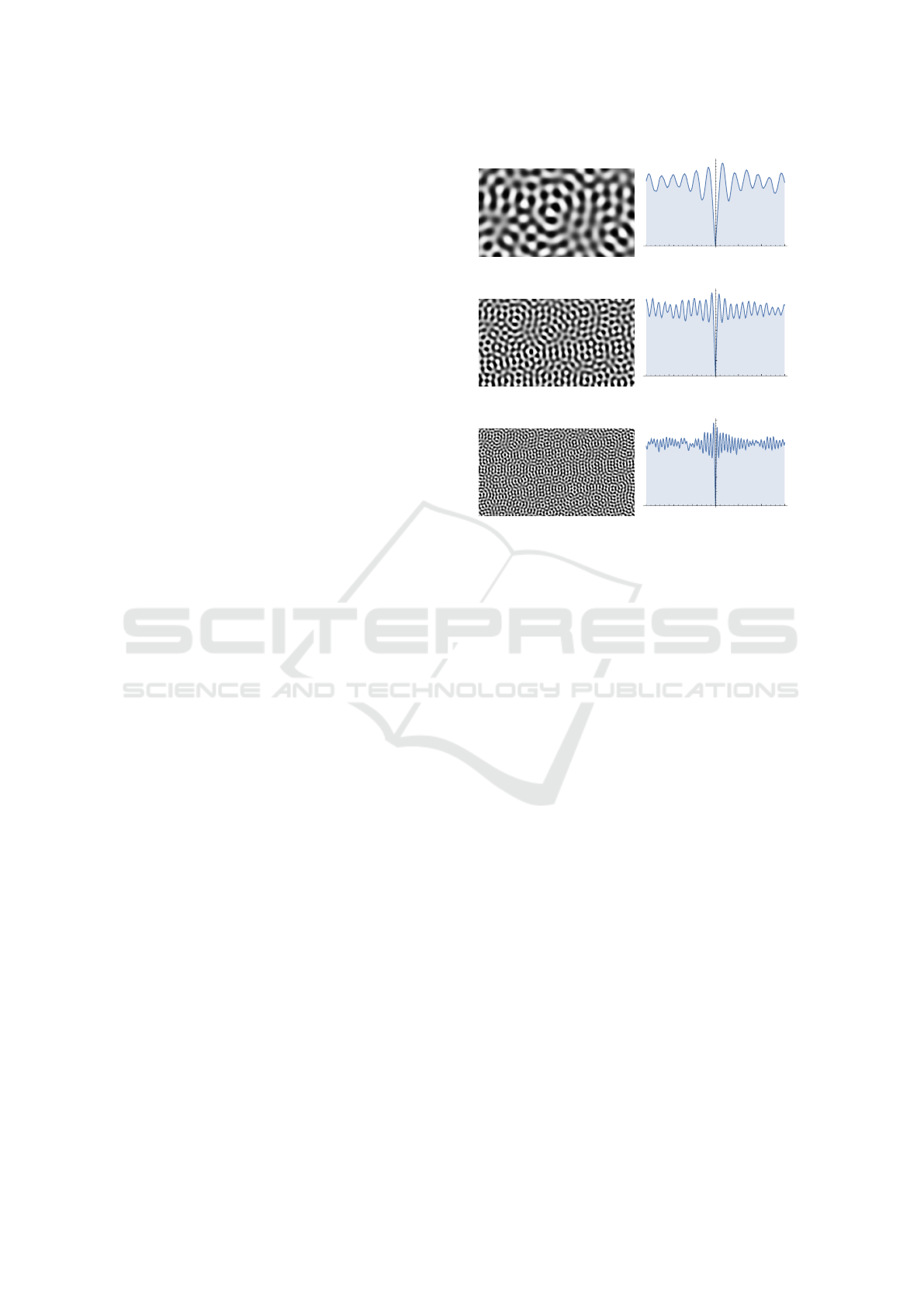
Figure 2: Unstructured light patterns at various spatial
frequencies and their cost functions representing the cost
of the difference between two neighboring pixels (here, a
neighborhood of 300 pixels). The frequency represents
the oscillation number of each sine per pattern. Notice
that when the frequency increases, the curve is more
pronounced. Fig. (a) shows a pattern frequency equal to
25, (b) shows a pattern frequency equal to 50 and (c) shows
a pattern frequency equal to 100.
3.1 Pattern Frequency
The unstructured light pattern frequency is the
oscillation number of one sine per pattern and is
the main property of the unstructured light patterns.
Increasing the pattern frequency reduces the impact
of indirect illumination and improves matches. Using
a very low frequency results in a high correlation
between neighboring pixels as they become too
similar to match effectively. The subpixel accuracy
increases when the frequency is high because the
curves of the cost functions are more pronounced and
smooth. Fig. 2 shows three patterns with different
frequencies and their associated cost function curves.
As shown in the figure, the curve becomes more
pronounced and precise as the frequency increases.
However, using a very high frequency brings about
several matching errors because the camera might not
be able to distinguish the black and white bands.
Subpixel Unsynchronized Unstructured Light
867

Figure 3: Illustration of pixel ratio where four projector
pixels see the same camera pixel (top) and only one camera
pixel sees a mixture of four projector pixels (bottom).
One can say that the projector-camera correspondences
is already subpixel whereas the inverse camera-projector
correspondences isn’t and it can be improved with a
subpixel accuracy.
3.2 Pixel Ratio
The pixel ratio represents the number of pixels seen
by a single camera pixel in the projector pattern, and
vice versa. The optimal case is for the pixel ratio
to be near 1. Indeed, a single pixel of the camera
corresponds to only one pixel in the projector. For the
current experiments, the pixel ratio is near 2 because
the camera sees a mixture of four neighboring pixels
in the projector (two pixels per axis). The subpixel
accuracy decreases as the pixel ratio increases. To
illustrate, consider an example of a pixel ratio near 2.
If the camera “sees” four neighboring projector pixels
then the correspondence from projector to camera
already has a subpixel accuracy of a half pixel per
axis. This is because the projector pixels have more
information and they are more accurate. As illustrated
in Fig. 3, we are already "inside" the camera’s
pixels. Thus, the pixel ratio is very important in
the determination of the subpixel matching, as it can
increase or decrease its precision.
3.3 Linear and Quadratic Code
Pixel correspondences between camera and projector
are established by using LSH algorithm (Locality
Sensitive Hashing) (Andoni and Indyk, 2006). LSH
is used in searching for nearest neighbors in very
high-dimensional spaces. Because of its inherently
random nature, it is necessary to run several LSH
iterations. At each iteration, it generates different
match proposals and keeps only the best ones based
on the difference of bits in the codes. While trying
to recover subpixel accuracy, codes from neighboring
pixels will be compared. These codes tend to be very
similar, so we rely on quadratic code instead of linear
code to get enough information.
As described in (El Asmi and Roy, 2018), a linear
code with a small number of LSH iterations is used
to find the first pattern of the captured sequence
and a quadratic code is used to estimate the mixture
between two consecutive unstructured light patterns.
For a given set of n patterns, a linear codeword is n
bits for n bits of information and a quadratic codeword
is
n
2
−n
2
bits providing n logn bits of information, as
explained in (Martin et al., 2013). To illustrate,
consider an example of 60 patterns, a linear codeword
is 60 bits for 60 bits of information and a quadratic
codeword is 1770 bits for 354 bits of information.
Thus, the quadratic code increases the amount of
information and reduces the LSH matching errors.
By increasing the number of bits, the quadratic code
increases the number of transitions (0 to 1 or 1 to
0) between neighboring pixels by a factor log n (in
our example,
354
60
≈ 6). This increases the subpixel
accuracy since it relies on those bit transitions.
4 SUBPIXEL ACCURACY
In order to establish the pixel correspondences
between the camera and the projector, an
unsynchronized unstructured light method is
used (El Asmi and Roy, 2018). Because this method
provides bidirectionality of the matches (camera to
projector and projector to camera), our method will
achieve subpixel accuracy in both directions. For
simplicity, only the process of estimating the subpixel
correspondences from the projector to the camera
will be described. As explained in the previous
section, subpixel matching assumes that a projector
pixel is observing a mixture of two adjacent pixels in
the camera image. This mixture can be described by
the parameters (δ
x
,δ
y
) which represent a non integral
displacement from an original integer match (ˆx, ˆy).
4.1 Selecting the Right Quadrant
Before finding the subpixel camera position for
any projector pixel, the discrete projector to
camera correspondence must be established by
using the LSH algorithm. We thus start with a
discrete match between projector pixel p
0
and
camera pixel p = ( ˆx, ˆy) to which a subpixel
displacement (δ
x
,δ
y
) is added to yield the exact
match. To estimate the subpixel displacement
(δ
x
,δ
y
), it is necessary to select the quadrant
which contains pixel p and its three neighboring
pixels. The subpixel position ( ˆx + δ
x
, ˆy + δ
y
)
is located between those four pixels of the camera
VISAPP 2019 - 14th International Conference on Computer Vision Theory and Applications
868

which are represented by
x ≤ ˆx + δ
x
= x + λ
x
< x + 1, x = b ˆx + δ
x
c (1)
y ≤ ˆy + δ
y
= y + λ
y
< y + 1, y = bˆy + δ
y
c (2)
so we can represent the subpixel position ( ˆx + δ
x
, ˆy +
δ
y
) as (x + λ
x
,y + λ
y
) where 0 ≤ λ
x
< 1 and 0 ≤ λ
y
<
1.
Because the chosen approach uses the
unsynchronized unstructured method, it is possible
that the projected patterns are mixed temporally in
the camera image. This mixture is always computed
individually for each camera pixel. For the case of
subpixel matching from projector to camera, the four
camera pixels forming the quadrant will each feature
a different temporal mixture. In the case of camera
to projector matching, a single mixture value will
be shared by the four projector pixels forming the
quadrant. In all cases, the temporal mixture must
be applied before a spatial interpolation in order to
obtain accurate subpixel matches.
4.2 Estimating the Subpixel Position
The subpixel position (λ
x
,λ
y
) is located inside
the region between the four selected neighboring
pixels {(x,y),(x + 1,y),(x,y + 1), (x + 1, y + 1)}.
Image intensities will be derived through bilinear
interpolation over the quadrant with the parameters
(λ
x
,λ
y
), defined as :
I[x + λ
x
,y + λ
y
] = (1 − λ
y
)I[x + λ
x
,y]
+λ
y
I[x + λ
x
,y + 1] (3)
where
I[x + λ
x
,y] = (1 − λ
x
)I[x,y] + λ
x
I[x + 1,y] (4)
with 0 ≤ λ
x
,λ
y
< 1.
In order to obtain the binary code of a pixel, we
select a number of intensity pairs from its codeword
and subtract them to get intensity differences. These
intensities are then binarized to provide the binary
code used by LSH for matching.
V [x, y] = I
i
[x,y] − I
j
[x,y]
∀(i, j) selected intensity pairs (5)
The intensity difference vector V is then binarized
into the code C as
C[x, y] = binarize(V [x,y]) (6)
where binarize(x) is 1 if x > 0, 0 if x < 0 and a random
sample from {0,1} when x = 0.
The idea for subpixel matching is that the
camera code will best match a projector code
which is obtained from image intensities which are
-2 -1 1 2
pixels
20
40
60
80
100
cost
freq 25
freq 50
freq 100
-2 -1 1 2
pixels
10
20
30
40
50
cost
freq 25
freq 50
freq 100
Figure 4: Pattern frequency representing the number of
oscillations of one sine in an unstructured light pattern. The
blue, orange and green curves correspond to a frequency of
25, 50 and 100 oscillations, respectively. These curves are a
cost function of the difference between neighboring pixels.
The curves (top) represent a binary difference between the
pixel codes and the curves (bottom) represent a continuous
difference of two vectors consisting of pixel intensities.
interpolated according to the subpixel position. In
practice, codes are quantized so they change in
steps, which is hard to minimize. By using the
non quantized vectors V [x + λ
x
,y + λ
y
], the cost can
be made continuous and easier to minimize using
gradient descent.
4.3 From Binary Cost Function to
Continuous Cost Function
Instead of quantizing the pattern intensity differences
V into a binary code C, we directly use V to compute
the subpixel value. Two vectors are calculated;
the first one, V represents the intensity differences
of the pixel p while the second one, V
0
, which is
a reference vector, representing the corresponding
coding intensities of the pixel p
0
.
The subpixel optimization will minimize the angle
between vectors V and V
0
, so the objective function is
simply defined as
cost[x + λ
x
,y + λ
y
] =
angle(V[x + λ
x
,y + λ
y
],V
0
[x,y]) (7)
where
angle(a,b) = arccos
a · b
kakkbk
(8)
Subpixel Unsynchronized Unstructured Light
869
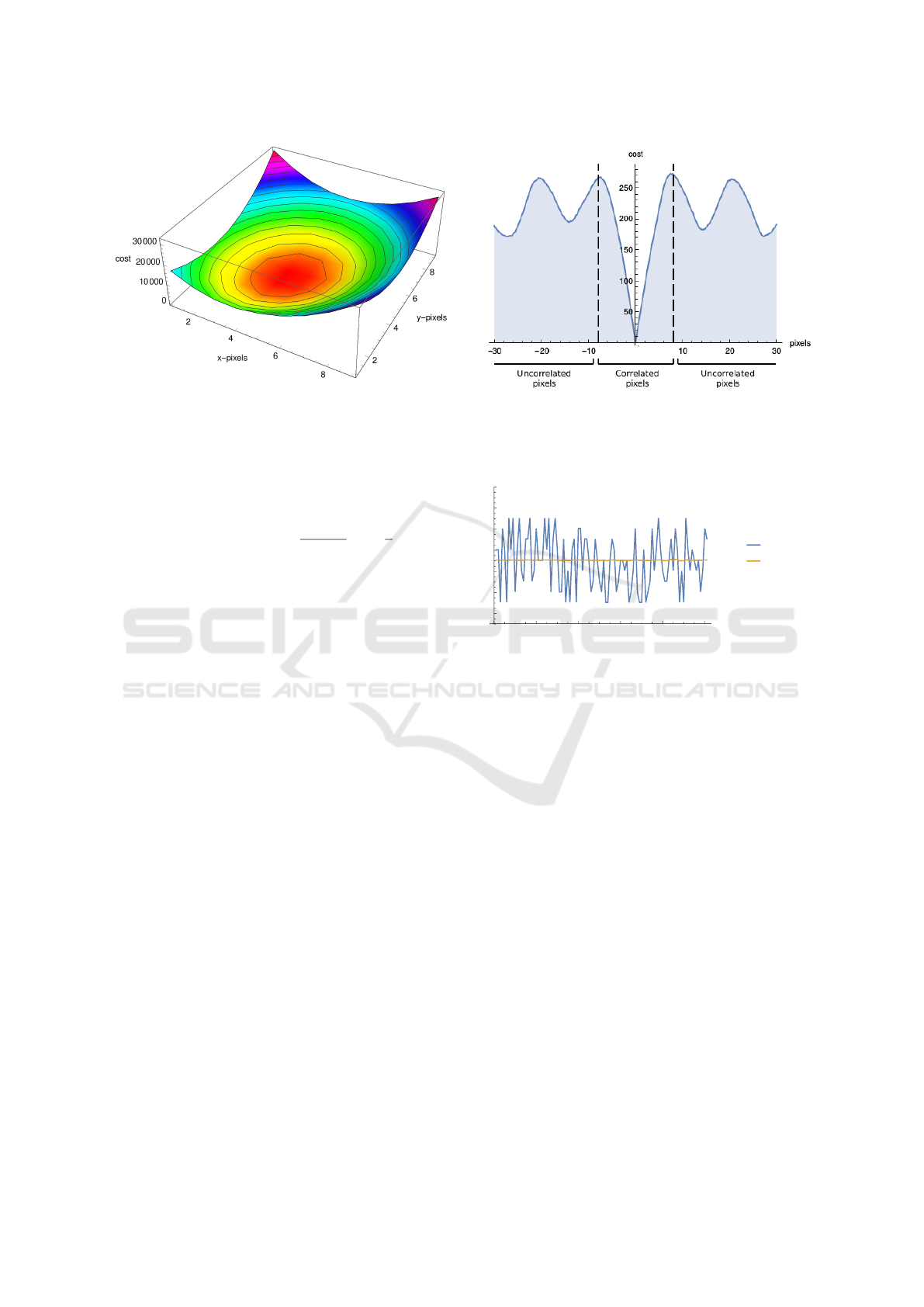
Figure 5: The x, y, and z axis represent the x, y pixels
and the cost of the difference between neighboring pixels,
respectively. We try to minimize this cost function curve.
In practice, for simplicity, we do not compute
the inverse cos and change this angle function to
approximately return the number of bit transitions:
angle(a,b) =
1 −
a · b
kakkbk
∗
n
2
(9)
where n is the number of bits in the code. This
cost has a minimum of 0 when a and b are aligned
(corresponding to an angle 0
◦
), an average of n/2 bits
when the angle is 90
◦
, when vectors are uncorrelated,
and a maximum of n when the vectors are inversely
correlated at 180
◦
.
The optimization estimates the subpixel match by
minimizing the cost over possible δ
x
and δ
y
, starting
at discrete position ( ˆx, ˆy).
Fig. 4 illustrates the difference between a binary
cost function and a continuous cost function. Binary
cost function curves feature steps where the gradient
is 0. In the continuous cost function, the curves are
much smoother and precise, so they are better to be
optimized on and the gradient descent can easily find
the minimum.
4.4 Gradient Descent
As explained above, we used a gradient descent to
reduce the computation time for the subpixel search
and increase its accuracy. Gradient descent iteratively
converges to the local minimum of a function
following the negative direction of the gradient at a
current point. We minimize the cost for the angle
between the two vectors, explained above in Sec. 4.3.
The obtained curve is a bowl-shaped curve. Our cost
function lends itself well to the minimization due to
its shape, as shown in Fig. 5, as it is locally convex,
as required by the gradient descent algorithm.
Figure 6: Cost function curve which shows that within
a specific neighborhood, ±10 pixels in this case, in the
unstructured light pattern, the cost is monotonous and easy
to minimize.
20 40 60 80 100
x-axis
94
96
98
100
102
104
106
y-axis
no subpix
subpix
Figure 7: Comparison of matches between matching twice
the same reference patterns adding a random noise. The
blue curve represents a correspondence without a subpixel
accuracy and the orange curve represents a subpixel
correspondence. Subpixel accuracy can improve and
correct the matching errors in the area where pixels are
correlated.
4.5 Correcting Match Errors
An important property of unstructured light patterns
is the correlation of the neighboring pixels. On
the contrary, there is no correlation between two
distant pixels because the patterns are generated
randomly. Fig. 6 illustrates the two parts of our
cost function and displays at which point is there
no more correlation between pixels. Using LSH
to establish the pixel correspondences between the
camera and the projector generates several matching
errors featuring a small deviation from the correct
match. The subpixel computation can correct these
matching errors, if the corresponding pixel is part
of the neighborhood where pixels are correlated.
However, if there is no correlation then the subpixel
cannot find the correct match. Thus, LSH errors
can be compensated by our subpixel method in some
cases, namely local matching errors.
VISAPP 2019 - 14th International Conference on Computer Vision Theory and Applications
870

For the sake of illustration, the same reference
patterns were matched twice adding a noise (±4
randomly to each matched pixel), a first time
without subpixel and a second time with the subpixel
matching. This noise generates a lot of LSH errors.
Fig. 7 illustrates the improvement of the matches.
In addition, if the frequency is very low then the
subpixel can improve and correct the matches because
the correlated neighborhood is wider. On the other
hand, if the frequency is very high, the subpixel has a
small area of convergence and can no longer correct
large matching errors (see Fig. 2). An example where
this matters is if you want to scan faces. In this case,
there is an upper limit to the usable frequency since
skin presents subsurface scattering which blurs high
frequencies. Nevertheless, our subpixel method can
compensate for the matching errors and increase the
accuracy and the quality of matches.
5 EXPERIMENTS
This section presents various experiments to evaluate
our method in real scenes as well as compare it
to other methods. Furthermore, the experimental
setup used to achieve these experiments is described.
Finally, two sets of results are provided; quantitative
results to compare subpixel accuracy between our
method and other methods, and qualitative results
to compare the quality of 3D models generated by
different methods.
In all the experiments, common off-the-shelf
equipment is used. The camera is a raspberry PI
at a resolution of 1280x720 and the projector is
an Aaxa HD Pico projector at its native resolution
of 1280x720. The projection and the capture are
accomplished at 30 fps. Many difficulties were
encountered with this common material such as the
auto gain, the auto focus and flicker. Auto gain is
the automatic brightness adjustment of the camera to
the illumination of the scene. Auto focus is the focus
done automatically by the camera to the scene depths.
This can thus change the calibration. Finally, flicker
is the mixture of colors that the camera sees. To
project an RGB image, most RGB projectors send
one color at a time, and should the camera have a
very short exposure time, then it can distinguishe
a mixture of each color. Thus, it is no longer
possible to triangulate and obtain 3D models. The
camera-projector system was calibrated with a simple
planar calibration (Zhang, 2000; Salvi et al., 2002). In
addition, our experiments were performed in difficult
conditions with a rolling shutter camera.
To evaluate the proposed method, it is compared
to the unsynchronized unstructured method without
subpixel (El Asmi and Roy, 2018) and to the Phase
Shift method (Srinivasan et al., 1984). In our
experiments, a looping video of 60 unstructured light
patterns is projected at 30 fps without synchronization
between the projector and the camera. Furthermore,
in order to unwrap the phase for the Phase
Shift method, 16 patterns of a shifted sine (8
patterns for each axis) are added to the 60
unstructured light patterns. The decoding step is
performed with the unstructured light patterns then
the subpixel is computed from the recovered phases.
Because the video is projected and captured at 30
fps, it is important to find the mixture between
two consecutive patterns using the unsynchronized
unstructured light method.
In this section are presented a first set of results
which consist of a quantitative comparison between
the three methods, then a second set which consists
of a qualitative comparison. The experiments are
accomplished on different real scenes; a plane, a
specular corner and a Lambertian robot. The results
presented above are the raw data obtained, no median
filter or equivalents were applied. For the calculation
of the phase in each period, a treatment is performed
on the neighboring points to unwrap the phase. Then,
for the triangulation of the 3D models, a selection of
the 3D points is carried out to remove the outliers or
the points with an aberrant depth (z = ±200), and this
for the three methods.
The first experiment is to compare
unsynchronized unstructured light methods with
and without subpixel accuracy. For this experiment,
60 unstructured light patterns are projected on a plane
with a pattern frequency of 50 (number of cycles per
image). The pixel ratio of this experiment is equal
to 2 (each camera pixel sees 4 neighboring projector
pixels, thus 2 pixels per axis). Fig. 8 presents a
comparison of the two methods. In this figure,
from the projector view, the addition of subpixel
precision improves the curve by making it smoother
as compared to its counterpart, without subpixel,
which has a step function shape. On the other hand,
from the camera view, the improvement is minimal
because of the pixel ratio. One can say that the
camera-projector correspondence already has some
level of subpixel accuracy.
For the second experiment, 60 unstructured light
patterns and 16 patterns of a shifted sine are projected
on a specular corner using a frequency of 50.
Furthermore, the same pixel ratio (near 2) has been
kept. Fig. 9 (top) shows the curves of the three
methods from the camera view; unsynchronized
unstructured light method without and with the
Subpixel Unsynchronized Unstructured Light
871

5 10 15 20 25 30
x-axis
690
700
710
720
730
740
750
760
y-axis
UU
UUS
5 10 15 20 25 30
y-axis
330
340
350
360
370
380
390
x-axis
UU
UUS
(a)
5 10 15 20 25 30
x-axis
638
640
642
644
646
648
650
y-axis
UU
UUS
5 10 15 20 25 30
y-axis
476
478
480
482
484
486
488
490
x-axis
UU
UUS
(b)
Figure 8: The curves represent a line extracted from two
LUTs; (a) the camera view and (b) the projector view.
The blue curve represents the unsynchronized unstructured
light method without the subpixel accuracy (UU) and the
orange line represents the unsynchronized unstructured
light method with the subpixel accuracy (UUS). The figures
left and right represent a number of pixels along the x and y
axis, respectively.
10 20 30 40 50
y-axis
440
460
480
500
520
540
x-axis
UU
UUS
PS
10 20 30 40 50
y-axis
-4
-3
-2
-1
1
err
UU
UUS
PS
Figure 9: The curves (top) represent a line extracted from
three LUTs; the blue curve represents the unsynchronized
unstructured light method without the subpixel accuracy
(UU), the orange line represents the unsynchronized
unstructured light method with the subpixel accuracy
(UUS) and the green curve represents the Phase Shift
method (PS). The curves (bottom) represent the average
error between the extracted line and a reference line passing
through all the points.
f=25
f=50
f=70
5 10 15 20 25 30
x-axis
715
720
725
730
735
y-axis
UU
UUS
Figure 10: Extracted line from two LUTs of an unstructured
light pattern projection with a frequency (f) of 25, 50
and 70; where the frequency represents the number of
cycles of each sine per pattern. The blue curve represents
the unsynchronized unstructured light method without the
subpixel accuracy (UU), the orange line represents the
unsynchronized unstructured light method with the subpixel
accuracy (UUS).
subpixel accuracy and the Phase Shift method. Fig. 9
(bottom) illustrates the average error of each method.
The average error is the difference between a line
extracted from the LUTs and the reference line. One
can notice that there is a slight improvement in the
unsynchronized unstructured light method curve with
subpixel compared to that without subpixel accuracy.
One can further notice that the error curve of the
Phase Shift method is shifted about 4 pixels because
of the specular surface of the reconstructed object.
For the third experiment, the scans are
accomplished at different frequencies. As explained
in Sec. 3.1, the pattern frequency has a significant
impact on subpixel accuracy. Fig. 10 shows a
comparison between the unsynchronized unstructured
light method with and without subpixel accuracy.
The pattern frequency of each scan is {25, 50, 70}. It
can be seen that the blue curves with the frequencies
25 and 50 are of step function shape. The curves
of the subpixel unsynchronized unstructured light
method are much smoother and have no steps. The
subpixel corrects even some matching errors because
the cost function curve is wider (Fig. 4, freq 25 and
50), so the neighboring pixels are correlated over a
larger zone (Fig. 6). On the other hand, the curve
with a frequency 70 is less smooth because the cost
function curve is very pronounced and the correlation
zone is very small (see Fig. 2). The mean and the
standard deviation show that the scan at a frequency
70 is better but that the subpixel cannot improve it
more as is the case of the frequencies 25 and 50, as
VISAPP 2019 - 14th International Conference on Computer Vision Theory and Applications
872
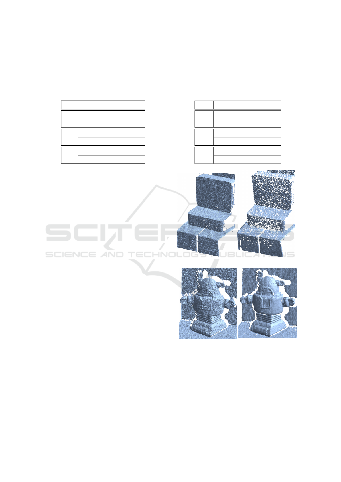
Table 1: The standard deviation of the difference (in
pixels) between a reference line and an extracted line
from each LUT in x-axis obtained with a different pattern
frequency for each set of unstructured light patterns. Mean
and std represent the mean and the standard deviation
for unsynchronized unstructured light methods with and
without subpixel accuracy, respectively.
freq subpixel mean std
25 without 0.255 0.167
with 0.163 0.112
50 without 0.241 0.169
with 0.082 0.065
70 without 0.225 0.123
with 0.140 0.128
shown in Table 1.
The last experiment in the quantitative results set
is the comparison of different pixel ratios. In this
experiment, the camera view is chosen and the pattern
frequency used is 50. The pixel ratio represents
the number of pixels matched between the camera
and the projector. We chose three different pixel
ratios to demonstrate the achievements of the subpixel
accuracy; a camera pixel sees only one projector pixel
(ratio = 1), a camera pixel sees 4 projector pixels
so 2 pixels per axis (ratio = 2) and finally a camera
pixel sees 16 projector pixels so 4 pixels per axis
(ratio = 4). Table 2 illustrates the results of the
unsynchronized unstructured light method and the
subpixel unsynchronized unstructured light method.
Mean and standard deviation represent the difference
between a line extracted from a LUT and a reference
line. The quality of the matches improves when
the pixel ratio increases (the average error and the
standard deviation decrease). On the other hand, the
higher the ratio, the less the subpixel improves the
quality as one can say that the correspondence is
already subpixel.
For the set of qualitative experiments, four
3D reconstructions obtained with the subpixel
unsynchronized unstructured light method and the
Phase Shift method are presented. Fig. 11 (a) shows
a specular corner and Fig. 11 (b) shows a Lambertian
robot. The Phase Shift model (right (a)) has several
holes due to matching errors. These matching errors
generate outliers that are removed during the step of
calculating polygons to form a 3D model. As a result
of the previously mentioned errors, the quality of the
matches of the subpixel unsynchronized unstructured
light method is deemed superior to the quality of
the matches of the Phase Shift method. This is
because the corner is specular and there is also
Table 2: The standard deviation of the difference (in
pixels) between a reference line and an extracted line
from each LUT in x-axis obtained with a different pixel
ratio for each set of unstructured light patterns. Mean
and std represent the mean and the standard deviation
for unsynchronized unstructured light methods with and
without subpixel accuracy, respectively.
ratio subpixel Mean std
1 without 0.190 0.133
with 0.088 0.122
2 without 0.148 0.112
with 0.109 0.084
4 without 0.081 0.059
with 0.057 0.053
(a)
(b)
Figure 11: Various scenes reconstructed in 3D. (a) shows
a 3D reconstruction of a specular corner (a right angle)
and (b) shows a 3D reconstruction of a Lambertian
robot. The 3D reconstructions (left) are obtained using the
unsynchronized unstructured light method with the subpixel
precision and the 3D reconstructions (right) are obtained
using the Phase Shift method. These unfiltered models are
obtained from the camera view.
Subpixel Unsynchronized Unstructured Light
873
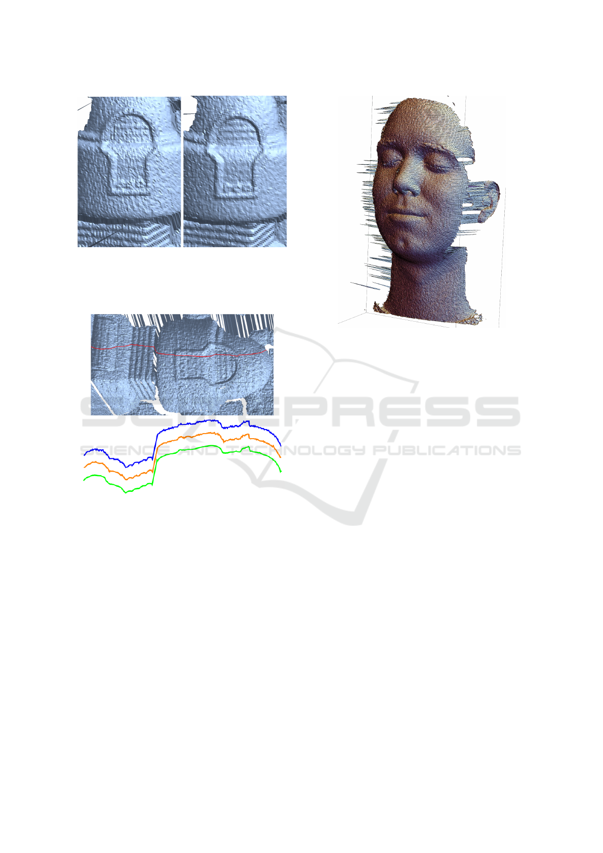
Figure 12: Reconstruction of a Lambertian robot. 3D
models are obtained with the unsynchronized unstructured
light method without subpixel accuracy (left) and with
subpixel accuracy (right). These unfiltered models are
obtained from the projector view.
UU
UUS
PS
Figure 13: x and y projection (bottom) of reconstructed
Lambertian robot for different methods. The blue curve
represents the unsynchronized unstructured light method
without the subpixel accuracy (UU), the orange line
represents the unsynchronized unstructured light method
with the subpixel accuracy (UUS) and the green line
represents the Phase Shift method. The figure (top)
illustrates the portion of the robot which is reconstructed.
a mixture between two unstructured light patterns
due to the unsynchronized capture. The subpixel
unsynchronized unstructured light method is robust to
specular objects and to the unsynchronized capture, as
shown in Fig. 11 (a) and (b) on the left. Fig. 12 shows
a 3D model achieved with the proposed method from
the projector view. The cropped image (right) shows
more details, obtained through the subpixel precision,
than the cropped image (left) which is achieved
without subpixel. Fig. 13 illustrates a section of the
3D model (robot). It shows the accuracy of each
method on a section of the robot. The quality of
Figure 14: 3D reconstruction using subpixel
unsynchronized unstructured light method of a face.
This unfiltered model is obtained from the projector view.
the reconstruction is very good and more details can
be noticed with subpixel unsynchronized unstructured
light and the Phase Shift methods.
The goal of this method is to quickly and
efficiently scan faces. In addition to scanning in less
than two seconds, the accuracy of the matches is
increased by adding subpixel. Fig. 14 illustrates a 3D
model of a face from the projector view. An excellent
3D model with the utmost precision is obtained using
the proposed method.
6 CONCLUSION
In this article, we proposed a new method to achieve
high subpixel accuracy using the unsynchronized
unstructured light method. This method increases the
precision of the correspondence between the projector
and the camera. The unsynchronized unstructured
light method makes scanning faces easier in difficult
conditions such as subsurface scattering, indirect
illumination and scene discontinuities. Relying on
low cost hardware without any form of temporal
synchronization and a high frame rate, at 30 fps and
60 fps, 3D models with the utmost precision can
be achieved. The subpixel estimation is fast and
simple, and can also correct errors of the discrete
correspondences for a better match quality.
VISAPP 2019 - 14th International Conference on Computer Vision Theory and Applications
874

REFERENCES
Andoni, A. and Indyk, P. (2006). Near-optimal hashing
algorithms for approximate nearest neighbor in high
dimensions. In Foundations of Computer Science,
2006. FOCS’06. 47th Annual IEEE Symposium on,
pages 459–468. IEEE.
Chen, T., Seidel, H.-P., and Lensch, H. P. (2008). Modulated
phase-shifting for 3d scanning. In Computer Vision
and Pattern Recognition, 2008. CVPR 2008. IEEE
Conference on, pages 1–8. IEEE.
Couture, V., Martin, N., and Roy, S. (2011). Unstructured
light scanning to overcome interreflections. In
Computer Vision (ICCV), 2011 IEEE International
Conference on, pages 1895–1902. IEEE.
Couture, V., Martin, N., and Roy, S. (2014). Unstructured
light scanning robust to indirect illumination and
depth discontinuities. International Journal of
Computer Vision, 108(3):204–221.
El Asmi, C. and Roy, S. (2018). Fast unsynchronized
unstructured light. In Computer and Robot Vision
(CRV), 2018 15th Conference on. IEEE.
Gu, J., Kobayashi, T., Gupta, M., and Nayar, S. K.
(2011). Multiplexed illumination for scene recovery
in the presence of global illumination. In Computer
Vision (ICCV), 2011 IEEE International Conference
on, pages 691–698. IEEE.
Gühring, J. (2000). Dense 3d surface acquisition
by structured light using off-the-shelf components.
In Videometrics and Optical Methods for 3D
Shape Measurement, volume 4309, pages 220–232.
International Society for Optics and Photonics.
Gupta, M. and Nayar, S. K. (2012). Micro phase shifting.
In Computer Vision and Pattern Recognition (CVPR),
2012 IEEE Conference on, pages 813–820. IEEE.
Herakleous, K. and Poullis, C. (2014). 3dunderworld-sls:
An open-source structured-light scanning system
for rapid geometry acquisition. arXiv preprint
arXiv:1406.6595.
Huntley, J. M. and Saldner, H. (1993). Temporal
phase-unwrapping algorithm for automated
interferogram analysis. Applied Optics,
32(17):3047–3052.
Inokuchi, S. (1984). Range imaging system for 3-d object
recognition. ICPR, 1984, pages 806–808.
Jaeggli, T., Koninckx, T. P., and Van Gool, L. (2003).
Online 3d acquisition and model integration. In
PROCAMS, ICCV Workshop.
Koninckx, T. P. and Van Gool, L. (2006). Real-time
range acquisition by adaptive structured light.
IEEE transactions on pattern analysis and machine
intelligence, 28(3):432–445.
Kushnir, A. and Kiryati, N. (2007). Shape from
unstructured light. In 3DTV Conference, 2007, pages
1–4. IEEE.
Liu, K., Wang, Y., Lau, D. L., Hao, Q., and Hassebrook,
L. G. (2010). Dual-frequency pattern scheme for
high-speed 3-d shape measurement. Optics express,
18(5):5229–5244.
Martin, N., Couture, V., and Roy, S. (2013). Subpixel
scanning invariant to indirect lighting using quadratic
code length. In Proceedings of the IEEE International
Conference on Computer Vision, pages 1441–1448.
Moreno, D., Calakli, F., and Taubin, G. (2015).
Unsynchronized structured light. ACM Transactions
on Graphics (TOG), 34(6):178.
Nayar, S. K., Krishnan, G., Grossberg, M. D., and
Raskar, R. (2006). Fast separation of direct and
global components of a scene using high frequency
illumination. ACM Transactions on Graphics (TOG),
25(3):935–944.
Rusinkiewicz, S., Hall-Holt, O., and Levoy, M. (2002).
Real-time 3d model acquisition. ACM Transactions
on Graphics (TOG), 21(3):438–446.
Sagawa, R., Furukawa, R., and Kawasaki, H. (2014). Dense
3d reconstruction from high frame-rate video using
a static grid pattern. IEEE transactions on pattern
analysis and machine intelligence, 36(9):1733–1747.
Salvi, J., Armangué, X., and Batlle, J. (2002). A
comparative review of camera calibrating methods
with accuracy evaluation. Pattern recognition,
35(7):1617–1635.
Salvi, J., Fernandez, S., Pribanic, T., and Llado, X. (2010).
A state of the art in structured light patterns for surface
profilometry. Pattern recognition, 43(8):2666–2680.
Salvi, J., Pagès, J., and Batlle, J. (2004). Pattern codification
strategies in structured light systems. PATTERN
RECOGNITION, 37:827–849.
Srinivasan, V., Liu, H.-C., and Halioua, M. (1984).
Automated phase-measuring profilometry of 3-d
diffuse objects. Applied optics, 23(18):3105–3108.
Takei, J., Kagami, S., and Hashimoto, K. (2007).
3,000-fps 3-d shape measurement using a high-speed
camera-projector system. In Intelligent Robots and
Systems, 2007. IROS 2007. IEEE/RSJ International
Conference on, pages 3211–3216. IEEE.
Wang, Y., Liu, K., Hao, Q., Lau, D. L., and Hassebrook,
L. G. (2011). Period coded phase shifting strategy
for real-time 3-d structured light illumination.
IEEE Transactions on Image Processing,
20(11):3001–3013.
Wexler, Y., Fitzgibbon, A. W., and Zisserman, A. (2003).
Learning epipolar geometry from image sequences.
In Computer Vision and Pattern Recognition,
2003. Proceedings. 2003 IEEE Computer Society
Conference on, volume 2, pages II–209. IEEE.
Wust, C. and Capson, D. W. (1991). Surface profile
measurement using color fringe projection. Machine
Vision and Applications, 4(3):193–203.
Zhang, S., Van Der Weide, D., and Oliver, J. (2010).
Superfast phase-shifting method for 3-d shape
measurement. Optics express, 18(9):9684–9689.
Zhang, S. and Yau, S.-T. (2007). High-speed
three-dimensional shape measurement system using
a modified two-plus-one phase-shifting algorithm.
Optical Engineering, 46(11):113603.
Zhang, Z. (2000). A flexible new technique for camera
calibration. IEEE Transactions on pattern analysis
and machine intelligence, 22.
Subpixel Unsynchronized Unstructured Light
875
