
Towards a Software Architecture for Near Real-time Applications of IoT
Dominik Grzelak, Carl Mai and Uwe Aßmann
Software Technology Group, Technical University of Dresden, Germany
Keywords:
Real-time System, Fog Computing, Distributed Robotics Systems, 3D Mouse.
Abstract:
The number of Internet of Things (IoT) devices increases and will become an ever important source of in-
formation made available through their sensors. As a result, devices form denser networks producing a huge
variety and volume of data. If intercommunication and interaction between many decentralized resources are
not considered as primary objective by vendors, networking distributed IoT devices will be complicated due
to their heterogeneity. Thus, mastering the challenge of collecting and processing data with low-latency is a
difficult task. In this paper, we present a practical and easy to employ reference software architecture for fog
computing application scenarios, enabling the communication between a multitude of devices which require
an efficient and robust real-time system. As proof, we conduct a practical demonstration—a three-dimensional
mouse is constructed, called the Cube-It, to control a six-joint robot (i.e., the UR10). The findings of this work
are expected to aid researchers studying the integration of heterogeneous IoT devices within fog computing
environments comprising many sensors and actuators.
1 INTRODUCTION
Billions of devices will be connected to the inter-
net until 2020 (Evans, 2011), forming a massive
machine-to-machine network between smart devices,
sensors, and actuators. The amount of data that is cre-
ated and send over the network vastly increases as
well. As IoT is becoming more prominent and the
number of devices increases, they will become an ever
important source of information as they are generat-
ing data through their sensors. From these, various
kinds of decisions can be made by leveraging the in-
terrelation of multiple sensor information. More and
more traffic in a network will be generated and be-
comes a burden for low-bandwidth and high-latency
networks. Therefore, applications of IoT must cope
with the vast amount of data and react and respond in
near real-time. Low-latency is an essential attribute
for IoT applications (Bonomi et al., 2014).
Former computing models such as the Cloud are
not sufficient for latency-sensitive applications and
distributed computing for a considerable number
of heterogeneous devices, sensors, and actuators
(Bonomi et al., 2012). So far, cloud-based solutions
are inadequate. As the physical distance between the
user and cloud increases, transmission latency and re-
sponse time increases as well. For the real-time re-
quirement, vast amounts of data in low-bandwidth
networks must be processed and transmitted. Con-
cerning the distributed computing requirement, a dis-
tributed system of devices communicating via central
nodes or directly with each other must be established
ad-hoc or permanently for facilitating the interoper-
ability among services and devices, but also scalabil-
ity.
The next logical step is to push the cloud services
to the edge of the network of the devices to gather
the actual data close to their respective origins. This
is known as fog computing. Data processing is per-
formed during its collection, enabling local decision
making at these devices instead of a physically distant
cloud server. This significantly reduces the amount of
data that is being sent through the network and re-
duces the bandwidth needed. We propose a fog com-
puting architecture for service-oriented IoT applica-
tions with the following objectives:
• Separation of Concerns (SoC): The connection
of new sensors and actuators is realized through
a data-driven approach leaving most of the ser-
vice logic unaffected when adding, changing or
removing hardware.
• Distribution: Handling distributed computing
among a vast number of devices through an ab-
stract message bus that provides means for data
exchange between services. Furthermore, ser-
vices are deployed near devices performing the
Grzelak, D., Mai, C. and Aßmann, U.
Towards a Software Architecture for Near Real-time Applications of IoT.
DOI: 10.5220/0007414101970206
In Proceedings of the 4th International Conference on Internet of Things, Big Data and Security (IoTBDS 2019), pages 197-206
ISBN: 978-989-758-369-8
Copyright
c
2019 by SCITEPRESS – Science and Technology Publications, Lda. All rights reserved
197

actual task to facilitate the near real-time require-
ment.
• Availability and Scalability: This objective in-
dicates that core parts of the architecture and ser-
vices of IoT applications are resilient to node fail-
ures. This is achieved by the provision of redun-
dant services and constant monitoring to recover
degraded services automatically.
1.1 Related Work
Bonomi et al. (Bonomi et al., 2014) expound a soft-
ware architecture for fog computing highlighting key
objectives such as low and predictable latency, geo-
graphically distributed devices and interplay with the
cloud. The main constituents of the architecture are
the fog abstraction layer (exposes a uniform inter-
face for management and control by providing APIs
for monitoring, provisioning and controlling physical
resources), orchestration layer (distributed, policy-
based life-cycle management of services, also includ-
ing a messaging bus), and the data APIs layer (ap-
plications use these to leverage the fog platform, e.g.,
storing and getting data). We, however, use the mes-
saging bus not only to transmit control messages for
service orchestration and resource management as in
(Bonomi et al., 2014) but also to carry application-
specific data as well as sensor and actuator data.
Lisa 2.0 (Negash et al., 2016) is a low-level IoT
framework based directly on a real-time enabled mi-
cro kernel RIOT. Therefore, the framework has a low
footprint, real-time guarantees, and low latency. In
contrast to our software architecture, messaging tech-
nology and service distribution is custom built and is
not integrating well with existing middle-wares.
A framework for home automation focusing on
privacy is ParaDrop (Willis et al., 2014; Liu et al.,
2016). This framework can be deployed, for exam-
ple, on WiFi access points due to its small footprint.
Thus, reducing the latency by bringing the middle-
ware closer to the data. The framework can be hosted
inside Docker containers, similar to our approach.
However, it is not clear whether the framework can
be extended with other messaging protocols as with
our architecture.
DIAT (Distributed Internet-like Architecture for
Things) (Sarkar et al., 2015) is an IoT middleware,
which focuses on context adaptivity and privacy. The
architecture of DIAT comprises the following three
layers, which form a stack, called the IoT daemon.
The virtual object layer which is closest to the physi-
cal world and provides a virtual representation of sen-
sors. The composite virtual object layer composes
multiple virtual object layers and allows distribution,
and enables discovery and matching of virtual ob-
jects. Lastly, the service layer which is closest to
the end-user and provides high-level control of all de-
vices. Even though this layered architecture is de-
signed for interoperability, this requirement is only
ensured among the three layers (the IoT daemon has
to run on every IoT object). Compared to our archi-
tecture, we utilize a data-driven approach for the rep-
resentation of sensors and actuators of the physical
world. The outputs and inputs are modelled using a
model language, decoupled from the software com-
ponents. This facilitates interoperability and integra-
tion between applications within our architecture and
completely different IoT applications.
1.2 Structure
Our paper is structured as follows. In Section 2,
we propose a novel concept of a low-latency soft-
ware reference architecture facilitating near real-time
applications for the fog. As proof, we demonstrate
the implementation and usefulness of our architecture
with one robotic demonstrator (Section 3)—a three-
dimensional mouse for real-time control of a robotic
arm. Our case study shows that we can implement
such an approach using our reference architecture. Fi-
nally, conclusions are offered in Section 4, were we
are also giving an outlook on what is left for future
work.
2 REAL-TIME SOFTWARE
REFERENCE ARCHITECTURE
FOR IOT APPLICATIONS
The system’s primary task is to route data between
multiple different IoT devices in a robust, efficient
manner in near real-time, allowing further data pro-
cessing in between the routes. Fog computing
serves as an optimal choice when requiring distribu-
tion, scalability and real-time (Bonomi et al., 2014;
Al-Fuqaha et al., 2015). Such fog-based systems
are characterized by their operational independence,
physical distribution, number and type of devices.
Thus, the requirements of the system are manifold.
Considering the challenges of IoT as described by
Al-Fuqaha et al. (Al-Fuqaha et al., 2015), we adopt
several of these and aligning them with the goals
established in the introduction (Section 1) to im-
plement our service infrastructure efficiently, includ-
ing (i) Fault-tolerance: Eliminating the single point
of failure (SPF)—if one service fails, the system
must still operate appropriately according to the task;
IoTBDS 2019 - 4th International Conference on Internet of Things, Big Data and Security
198

(ii) Scalability: Functionality on devices must be de-
ployed automatically when the network load reaches
a critical limit; (iii) Performance: Achieving min-
imal lag between sensor readings, estimation, pro-
cessing and finally control; (iv) Updatability: Ensur-
ing on-the-fly updates leads to a more robust, reliable
software.
2.1 Architectural Components
This section introduces and discusses the components
and technologies that are used as the building blocks
for the proposed software architecture explained in
Section 2.2.
OSGi. The OSGi Alliance specifies the OSGi stan-
dard for the modularization of Java applications in
a service-oriented manner as the Java platform itself
provides limited support for packaging and deploying
Java-based applications.
1
As a result, to resolve this
issue, the OSGi framework uses the notion of bundles
which define a unit of modularization.
A bundle is a Java ARchive (JAR) file which con-
tains various resources and Java class files to provide
functionality and can also embed additional JAR files.
Within the OSGi framework bundles provide a stan-
dard to share and deploy components as bundles. The
visibility of bundles can be controled by hiding them
from other bundles or make them visible only for a
specific group. Moreover, the framework provides
mechanisms to define constraints to match imports to
exports.
Docker. Docker
2
is an open source project based
on Linux containers that enable an isolated, self-
contained unit for development, deployment, and ex-
ecution of programs. The usage of kernel features en-
ables the creation of self-contained environments for
applications that can be built, shared, deployed and
executed on-demand. Everything that is needed to run
the software is part of the container.
Kubernetes. One of the central points in fog com-
puting scenarios is the deployment of workflows close
to computing, storage and networking devices and de-
vices that generate data. This concept enhances pri-
vacy, minimizes lags and delays. Furthermore, data
that needs to be transferred to cloud endpoints is min-
imized. In Kubernetes
3
, a cluster represents a collec-
tion of hosts and their resources, including comput-
1
OSGi Core Release 5, http://www.osgi.org
2
https://www.docker.com/
3
https://kubernetes.io/
ing, storage and networking to run workloads. Hosts
are either physical or virtual machines that run work-
loads packaged as pods.Bundles are packaged in con-
tainers, which in turn are then deployed with Kuber-
netes at the, possible heterogeneous, edge devices.
MQTT. Message Queuing Telemetry Transport
(MQTT) (ISO/IEC, 2016) is a lightweight and widely
used messaging protocol on top of TCP/IP and is used
for machine-to-machine (M2M) communication with
built-in support of quality of service (QoS). It is opti-
mal for real-time communication between embedded
devices in low-bandwidth environments with its bi-
nary format containing only 2 bytes of header infor-
mation.
MQTT implements the publisher/subscriber mes-
sage pattern using a broker. Each client connects to a
broker and can subscribe to topics and publish mes-
sages through the broker. The broker is responsi-
ble for delivering messages to the subscribed clients
while it receives all messages from the clients and
sends them to all clients subscribed to a specific topic.
A topic is a hierarchically structured string where one
or more levels can be defined when a forward slash
separates them. The most popular open source MQTT
broker implementation is Mosquitto (Light, 2017).
2.2 System Description
A high-level description of the proposed architecture
is shown in Figure 1. The core of our infrastructure is
a service-based middleware which provides efficient
support for service acquisition, discovery, and deploy-
ment on edge nodes. Each service (that is, an OSGi
bundle) is developed and deployed separately. Each
bundle runs independently with its own set of func-
tionality, communicates through the central message
bus and works together with other services to carry
out specific tasks. The logic of the workflow can be
separated into different services and distributed ac-
cordingly in the edge network. This degree of mod-
ularity is realized using OSGi and MQTT (refer to
Section 2.1).
The services are deployed on different hosts and
interact with each other through the message bus.
Services can request other services even on differ-
ent hosts (dependency). The dynamic service injec-
tion and update into the system are supported with-
out the need to restart the whole application (see Sec-
tion 2.3). Nevertheless, services are bound to their
current scope in the running JVM. To allow distri-
bution across several devices in the network edge
the deployment and scaling of services is performed
Towards a Software Architecture for Near Real-time Applications of IoT
199
through the orchestration layer (see Figure 1 and Sec-
tion 2.5).
The message bus (see Section 2.4) is a cluster of
message brokers. A message broker consumes mes-
sages from producers and publishes these to its con-
sumers. Multiple brokers form a cluster. The cluster
is accessed through a load balancer to give a single
point of entry and is managed by the orchestration
layer as well (see Section 2.5).
Furthermore, the orchestration layer’s task is to
monitor the health of each service, the load balancer
and message broker cluster based on several QoS met-
rics. For example, in case the load balancer should
fail to be available under critical network load, the or-
chestration layer will be responsible for the provision
of redundant load balancers.
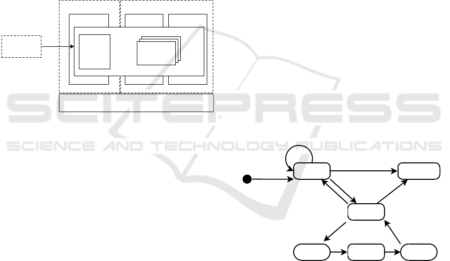
Service
3
Service
2
Message Bus
Service
1
IoT Device
Host B
Host A
Orchestration Layer
Load
Balancer
Message
Broker
Message
Broker
Message
Broker
Figure 1: High-level system infrastructure for applications
of IoT. Services are deployed on different hosts (here Host
A and Host B). The services interact with each other through
the message bus. The message bus comprises a cluster
of message brokers where the cluster is accessed through
a load balancer. Services can request other services (de-
pendencies) deployed on different hosts. The orchestration
layer manages the deployment of the services and message
bus components. Additionally, it is ensuring its scalability
under load. Devices which are not able to host services on
themselves due to limited processing power, can access the
functionality of other services via the message bus and also.
Data processing takes places on edge nodes at the
edge computing layer, thus, minimising latency and
enabling shorter response-times. This improves the
overall application performance when computing can
be done locally next to edge devices where the data
is generated, and actions are executed. To allow this
kind of distributed processing the services communi-
cate over the message bus with each other. This ab-
straction layer allows the implementation of various
message queue technologies.
Regarding the representation of sensors and ac-
tuators, we utilize a data-driven approach. There-
fore, a platform-agnostic language is used, which al-
lows to describe the inputs and outputs of the hard-
ware. At the same time, the model allows the gen-
eration of source code for a variety of programming
languages which can be used to serialize and deseri-
alize the hardware’s data. For example, the data for-
mat for the information exchange of sensor and actu-
ator data is achieved using a message format such as
Cap’n Proto, Google Protobuf or Apache Avro.
communicate with actuators by transmitting the
changes back or read sensor values directly in the
service—all specified in advance by the model.
2.3 Dynamic Services
We use concierge on edge nodes as a lightweight
version of the OSGi framework, which currently
implements the OSGi Core Specification R5 stan-
dard. This small-footprint implementation is opti-
mized for mobile and embedded devices (Rellermeyer
and Alonso, 2007), which makes this implementation
variant of OSGi preferably in IoT environments. The
key features of OSGi, including modularity through
the bundle concept, runtime dynamics for managing
components at runtime and the possibility of inter-
component communication through services.
OSGi enables on-the-fly updates of the services
through its dynamic services without restarting the
system. Services are going through a specific lifecy-
cle that is depicted in Figure 2, and closely correspond
the OSGi bundle lifecycle. The dynamic nature of the
Installed Uninstalled
Resolved
update
uninstall
update
resolve
uninstall
install
ActiveStarting Stopping
stop
start
Figure 2: Bundle lifecycle.
OSGi platform transitions a bundle through different
states in their lifecycle. The lifecycle shows how a
bundle transits from one state to another. The sys-
tem moves a bundle dynamically at runtime between
the installed, resolved, active, and uninstalled state
depending on their current constraints. As a result,
for instance, the starting order of the services are not
important even if they depend on each other or rely
on specific functionality. Since the state of each ser-
vice is submitted to the interested partner component,
it can wait until the corresponding service becomes
available.
IoTBDS 2019 - 4th International Conference on Internet of Things, Big Data and Security
200

Services are looked up via the OSGi Service Reg-
istry whereas the Service Provider is used to pub-
lish services. Thus, OSGi follows the principles of
a service-oriented architecture (McAffer et al., 2010).
As mentioned in the introduction of this section, ser-
vices are limited to the JVM on which they are run-
ning. To locate services that are distributed on other
devices, we perform deployments managed by Kuber-
netes (see Section 2.5) allowing the automatic orches-
tration of services. That enables services to define
dependencies that are deployed on other hosts. This
kind of service associations enables high reliability of
the entire system compared to statically wired depen-
dencies which make it hard to change functionality at
runtime without shutting down the system.
2.4 Message Bus
The message bus is a vital aspect of a distributed pro-
cessing system. Each device and service interacts
with each other over a network. In order to handle
the coordination of each participant in the system,
the communication is carried out by sending mes-
sages over a bus system. This allows an event source
to send many fine-grained events to several listeners.
Regarding OSGi, the Event Admin Service is provided
to allow the realisation of an Event Broker pattern.
The Event Admin offers message-based functionality
through publish/subscribe feature.
Different message bus variants can be imple-
mented due to the fact that the whole messaging
queue layer is completely abstracted away via the
OSGi Event Admin Service. As a result, there ex-
ists virtually no limitation for utilising any message
queue technology. For instance, on the one hand
it is possible to employ Apache Kafka for real-time
data analysis of sensor data with a very high through-
put. On the other hand, MQTT is preferably used in
low-bandwidth and high-latency environments which
makes it an optimal candidate for single-board com-
puters with CPU limitations. Even IoT devices can
communicate directly with services in the environ-
ment via a Kafka REST proxy or MQTT. For exam-
ple, services can subscribe to a topic and then collect
data coming from these devices and propagate further
actions. Updates of the current actions can be sent
back to the devices as well.
In the following, two different message system
variants are illustrated. Both examples demonstrate
the scalability of the system while redundant brokers
are provided and, thus, achieving the necessary load
balancing, orchestrated for instance, by Kubernetes.
2.4.1 MQTT Message Bus
The MQTT broker is distributed on many nodes in the
network to provide failsafe operations. This is called
an MQTT broker cluster which logically acts as one
logical broker. A load balancer is implemented to give
each client a single point of entry when communicat-
ing over MQTT. As a result, each single MQTT bro-
ker is not exposed directly to the clients. Moreover,
the load balancer decides, based on different measure-
ments (e.g., availability, capacity, and so on), which
client should connect to which broker. If the network
load increases, Kubernetes can deploy more MQTT
broker inside a cluster to compensate high network
loads and requests. The MQTT client itself will not
notice that as it is using this service via the load bal-
ancer.
2.4.2 Kafka Message Bus
Apache Kafka
4
is a distributed messaging system,
where Apache Zookeeper
5
is used as a load bal-
ancer to coordinate a Kafka cluster consisting of many
Kafka brokers (that is, a node in a cluster). A Kafka
broker manages the publishing and receiving of mes-
sages associated to topics for several consumers and
producers. Regarding the communication of IoT
devices with our presented system, a Kafka REST
Proxy
6
can be utilized. REST is platform-agnostic,
thus, enabling almost every embedded computer to
send HTTP requests. The REST proxy provides an
interface to a Kafka cluster.
2.5 Service Composition and
Orchestration
The task of the orchestration layer in conjunction with
OSGi includes the maintenance and extension of ser-
vices on-demand. Thus, guaranteeing the flexibility
and scalability of the system as required in the intro-
duction of Section 2.
Single services can be deployed on any device on-
demand assuming the necessary device requirements
are met. This enables services to request dependen-
cies from remote devices as if they were running in
the same JVM. The orchestration layer contains a ser-
vice registry which manages all deployed services of
the different devices. Since services can specify de-
pendencies to other registered services, the task of the
service registry is to make the dependencies available
4
https://kafka.apache.org/
5
https://zookeeper.apache.org/
6
https://github.com/confluentinc/kafka-rest
Towards a Software Architecture for Near Real-time Applications of IoT
201

to other services. Therefore, the services are regis-
tered first to resolve the interdependencies between
services later and to provide them accordingly.
For the presented 3D mouse case study (see Sec-
tion 3), the individual components of the whole ap-
plication (e.g., sensor data filtering and inverse kine-
matics calculation) are deployed on different devices
depending on the device’s performance or locality.
This enables the deployment of a service on a device
near the physical location where the action takes place
(e.g., actuator responsible for moving the robotic
arm).
3 A CASE STUDY: 3D MOUSE
FOR ROBOTIC CONTROL
Robotic co-working is becoming an important aspect
when humans and robots must work together in com-
plex environments (Aßmann et al., 2017). Robots
still do have very limited knowledge of their sur-
roundings when they are brought into new environ-
ments (de Rengervé et al., 2011), for instance, in man-
ufacturing, the automotive industry or the medical
sector. To gain the necessary knowledge via on-line
learning methods is a slow approach (de Rengervé
et al., 2011), and therefore often not appropriate
for automating processes in manufacturing nowadays.
Primarily, the objective is to reduce the costs by accel-
erating the processes considering minimal transitional
and implementation time. So far, robots were pro-
grammed directly without human interaction. How-
ever, this is a time-consuming and costly process
where the results often do not generalise well enough
within changing environments (Huang et al., 2015).
Therefore, programming the robot by imitation
is an often used paradigm—also known as Program-
ming by Demonstration (PbD) (Billard et al., 2008)
or Learning from Demonstration (LfD) (Argall et al.,
2009) in the literature—which is a much more prefer-
able and appropriate solution to the mentioned prob-
lem (Bakker and Kuniyoshi, 1996; Dillmann et al.,
2000; de Rengervé et al., 2011). A conceptual frame-
work for robot imitation was proposed by (Bakker and
Kuniyoshi, 1996), which states that an agent must
contain the three fundamental processes to imitate
an action from a teacher: observation, representa-
tion and reproduction. This allows the integration and
migration of robots into new environments to opera-
tionalise them immediately. Especially for such sce-
narios real-time requirements must be guaranteed.
Regarding the PbD paradigm, we describe the
construction of a low-cost device (functioning as 3D
mouse to control the robot) and the corresponding
near real-time system using our proposed reference
architecture.
7,8
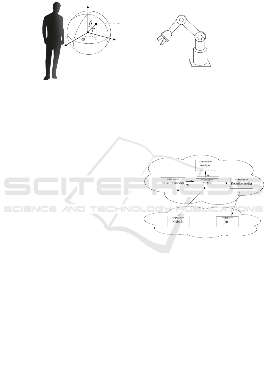
As a result, the device’s motions (that
is, the motion of a user) are instantly imitated by the
robot without learning involved. The use of this 3D
mouse is illustrated in Figure 3 which represents a
point in space, a so-called vectorial cursor. The de-
vice captures the user’s movement in mid-air and con-
trols the robot’s end effector. The presented 3D mouse
is self-contained without the need for transmitters or
receivers to detect signals in an environment (e.g., a
smart room). The device’s coordinates are described
by the three-dimensional position vector x = [r,θ,φ]
|
in spherical coordinates.
3.1 Experimental Equipment
3.1.1 Cube-It
The Cube-It is regarded as an intelligent thing and
serves as an abstract IoT device. It has the form
of a cube where the housing is made out of card-
board with a dimension of 100 mm × 100 mm ×
100mm (H × W × D). A Feather M0 from Adafruit
is used as portable microcontroller board with an
ATSAMD21G18 processor running at 48 MHz with
3.3 V power (see Figure 4a).
Connected to the Feather M0 is the BNO055, a
9-DOF sensor to acquire necessary orientation value
along two axes, namely φ and θ. The sensor values
are sent via the integrated WiFi chip. Further, an ad-
ditional IMU is integrated into the Cube-It. We are
using the x-OSC NGIMU to measure the radial dis-
tance in relation to the user’s position. The x-OSC
NGIMU has its own WiFi module to send data via the
Open Sound Control (OSC) (Wright, 2005) Protocol.
On the one hand, this architecture of the Cube-
It allow us to send data via two independent WiFi
clients, and on the other, the real-time system enables
independent processing of these two data channels,
thus, allowing the continuous operation of the robot
at least in one spatial dimension in case one of the
components fail.
Now, we explain how the sensor data of the Cube-
It is used to acquire all three elements of the position
vector. The Cube-It serves as an input device repre-
senting a vectorial point in mid-air which is updated
by the user’s motions. Let us define a 3-dimensional
7
We are speaking about near real-time systems as the
motion of the robot will always lag behind the motions of
the user in this scenario, even when it is kept very small.
The reason is, we first must compute the current position of
the 3D mouse, then transmit the data using the system, and
finally, the robot can be moved so that it follows the target.
8
https://www.youtube.com/watch?v=GDY0dwD3ntU
IoTBDS 2019 - 4th International Conference on Internet of Things, Big Data and Security
202
Base Frame
Elbow
Shoulder
End Effector
Initial Position (Origin)
New Position
Figure 3: Handling of the 3D mouse. The position of the mouse in mid-air is mapped to the end-effectors position. The two
black squares on the left-hand side denote the initial and the new position of the 3D mouse. The initial position of the device
also represents the origin of its coordinate space. The translation of the device is described by the vector [r,θ,φ]
|
which is
necessary to control the end effector.
position vector x = [r,θ,φ]
|
describing a point in a
spherical coordinate system. This point is a local rep-
resentation of the robot’s end effector. The origin of
this system can be any point relative to the user’s body
preferably the half arm’s length (as this is the most
natural position to use the 3D mouse). The height
is an irrelevant parameter due to the use of spherical
coordinates; thus, the 3D mouse is used in mid-air
independently from the height. The sensors deliver
orientation information and acceleration data. Both
angular values, φ and θ, are gathered by the orienta-
tion sensor. The radius r is determined by computing
the magnitude of the displacement in space, provided
by the acceleration data of the IMU, where the origin
is the position of the device relative to the user’s body
in the xy-plane.
3.1.2 UR10
We use the UR10 from Universal Robots
9
for our ex-
perimental validation (see Figure 4b). For this case
study we use the following three joints: the base,
shoulder and elbow of the UR10. The company de-
velops co-robots and provide 6-axis robot manipula-
tor arms of different sizes. Currently, two production
lines exist, where each robot in its line has a different
payload and reach, but they share the same features.
The robot can be customized with various end effec-
tors, accessories, and software.
The UR10 has a maximal range of action of ap-
proximately 1300 mm. Moreover, each joint of the
robot has a working range ±360
◦
with a maximum
speed of ±120/Sec. Each joint can be controlled in-
dividually, or in parallel together with other joints.
9
https://www.universal-robots.com/
3.2 Deployed Services
In this section, we describe the individual services of
our example application scenario to steer the robot
(see Figure 5).
Fog
IoT
MQTT bytes
OSC bytes
Cluster
Figure 5: Implementation variant of the reference archi-
tecture as illustrated in Figure 1. Shown are the fog (top)
and IoT layer (bottom). The fog layer consists of the dis-
tinct services centred around the MQTT broker, and the IoT
layer comprises the Cube-It and UR10. The MQTT broker
is used for communication between and inside each layer.
Additionally, the Cube-It communicates over the OSC pro-
tocol with the CubeItConnector service directly.
Services contain certain parts of the whole func-
tionality described by the internal model of the 3D
mouse. These services are distributed on the different
edge or fog devices in the local network allowing the
data processing near devices which are producing the
data. Thus, connecting the edge and IoT layer. With
reference to the proposed architecture (see Figure 1),
we only use one MQTT broker for the realisation of
the message bus. The orchestration layer utilises Ku-
bernetes, which monitors the state of the broker and
in case of a failure, it will restart the broker.
First, the Cube-It transmits data via MQTT. For
Towards a Software Architecture for Near Real-time Applications of IoT
203
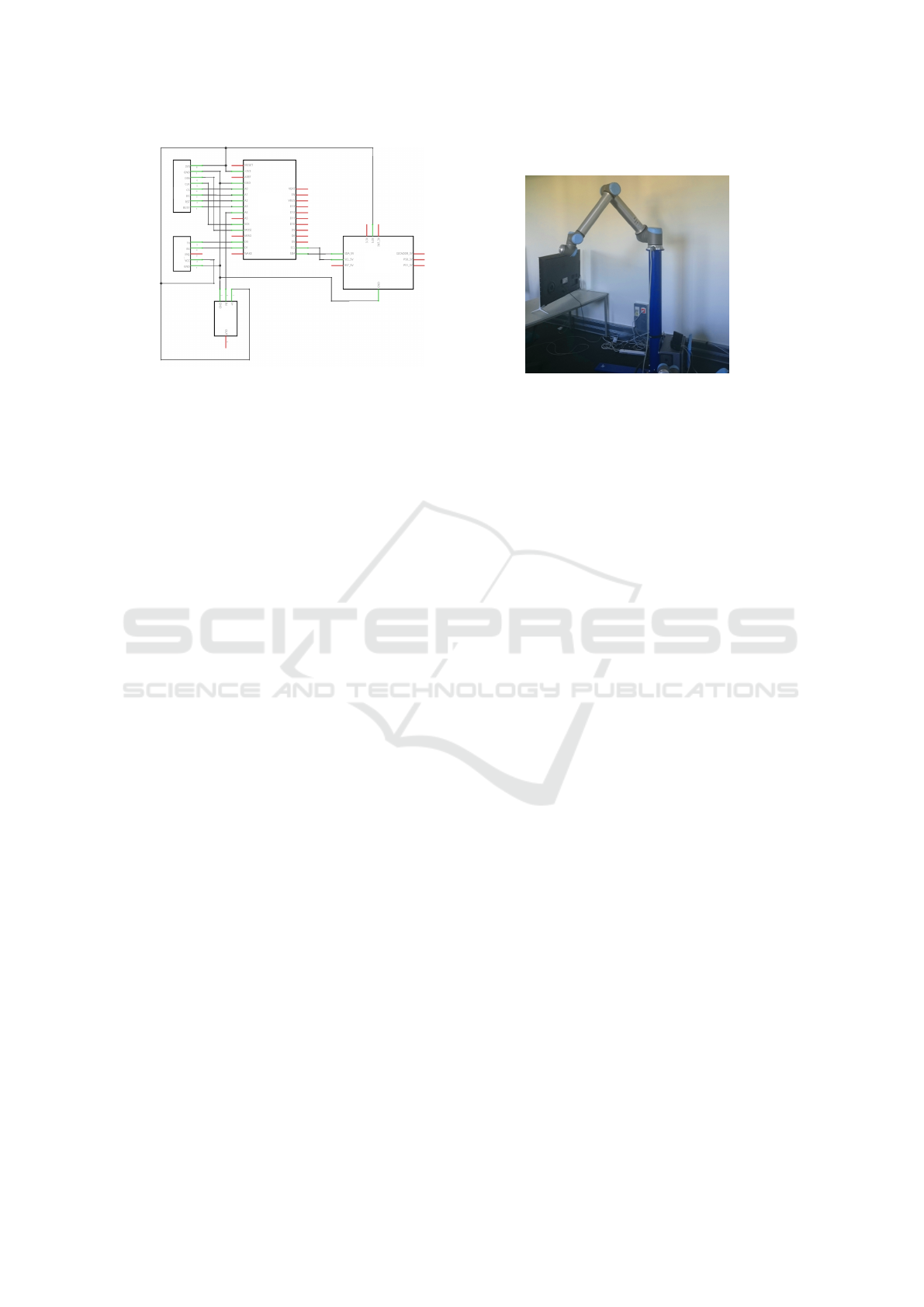
A) Adafruit Feather M0, WINC1500
B) 9-DOF Absolute Orientation IMU
Fusion Breakout BNO055
C) e-Ink Display
D) NFC
E) Adafruit FLORA NeoPixel
A)
B)
D)
E)
C)
(a) The representation of the electronic circuit of the
Cube-It is shown. The x-OSC NGIMU is not integrated
into the depicted circuit itself but inside the housing of
the Cube-It.
(b) Image of the UR10 in use for the experimental
demonstration.
Figure 4: Equipment used in our case study: A Cube-It, representing the 3D mouse, and the UR10.
that, the MQTT client of the Cube-It directly com-
municates with the MQTT broker. We created the
two topics o/orientation and o/acceleration
to send the angles and acceleration values of the
Cube-It in separate channels, respectively. After the
broker receives the message, it forwards it to the
CubeItConnector service. The data format of the
sensor readings (i.e., the sensor model) is specified
with Google’s Protocol Buffers Format. All services
rely on the same data model. To clarify, the generated
code from the model is used within all services of the
application.
We defined two message formats, on the one hand
for the orientation data, on the other for the accelera-
tion data. Each message contains the current state of
the Cube-It for a single time step. The message for the
orientation contains angle values for all three axes, a
“face” property (indicating the upwards pointed sur-
face of the device, perpendicular to the floor), and
three distinct time properties storing the sending, re-
ceiving and processing time. The message format for
the acceleration data of the Cube-It gathered by the in-
tegrated IMU (see Section 3.1) is defined analogously
to the orientation message format. In this case, the
OSC protocol is used to transmit the data over user
datagram protocol (UDP) to the CubeItConnector
service for further processing which implements an
OSC listener.
Secondly, as the CubeItConnector receives the
data packages, they are forwarded to the Analyzer
service. Before that, the connector validates the
data and performs some initial pre-processing. The
Analyzer service contains the whole functionality of
the 3D mouse model and computes the inverse kine-
matics.
Third, the results of the computations are sent to
the RobotController service. It contains the con-
trol classes to interact with the UR10 via TCP/IP over
the network. The IP address of the robot is stored in
a configuration file which can be changed at runtime.
A simulation can be run, or the actions can be trans-
ferred directly to the physical instance of the UR10.
3.3 Summary
Figure 1 presented the components of our data-driven
and service-oriented reference architecture. From our
implementation in Figure 5 it is observed that the ini-
tial objectives SoC, distribution, and availability and
scalability are achieved.
Scalability and availability are achieved through
the orchestration layer. The QoS monitoring ser-
vice within Kubernetes detects degrading or failed
services. On that basis, appropriate load distribu-
tion for services of an IoT application can be carried
out which also includes internal services such as the
MQTT brokers.
The implemented OSGi architecture covers the
updatability aspect. Moreover, it provides the ba-
sis for a service-oriented design. Thus, an IoT ap-
plication encompasses modular software components
which can be added, changed, or removed at runtime
without stopping the system. Fixing bugs and testing
becomes more straightforward. Consider the follow-
ing use case examples. If we want to include a robot
simulator, we can do so without affecting other com-
ponents. If the robot should be exchanged, we only
have to swap the controller service. The analyzer and
connector remain the same. Adding a new input de-
vice is accomplished by only changing the data model
IoTBDS 2019 - 4th International Conference on Internet of Things, Big Data and Security
204

within the connector service to conform the input pa-
rameters of the analyzer service. If we want to add
motion prediction we have to add a new component
next to analyzer where the rest is not touched.
4 CONCLUSION
This work aimed to create a usable software architec-
ture of a near real-time system following fog comput-
ing principles.
Therefore, we proposed a fog computing archi-
tecture for service-oriented IoT applications based on
the OSGi standard, allowing dynamic deployment of
services that act as IoT application components. Ser-
vices can be dynamically updated or injected on-the-
fly without restarting the whole application. Thus, the
proposed software architecture makes it very conve-
nient to deploy and distribute the changes back into
the edge network. Furthermore, the architecture al-
lows dynamic (permanent or ad-hoc) integration of a
large number of services and IoT devices.
Following our reference architecture, we showed
an implementation variant and demonstrated the use-
fulness for a fog computing scenario. The Cube-It,
representing the 3D mouse, was built to control the
movement of a robot based on the motion of a user.
On the basis of the data-driven hardware models for
sensors and actuators, our architecture allowed to vir-
tually interchangeably use any IoT device with mini-
mal effort regarding the configuration.
Future Work. First, we plan to conduct more ex-
periments to evaluate our architecture. In this work
we have not addressed the performance of the archi-
tecture. A comparative analysis of the performance
(regarding high availability and resilience of node
failures) between the proposed implementation and
existing architectures is left for future work.
Another interesting open issue to investigate is the
behavior of the system under dynamic integration of
a large number of services and IoT devices.
ACKNOWLEDGEMENTS
This project has received funding from the Elec-
tronic Component Systems for European Leadership
Joint Undertaking under grant agreement No 692480
(IoSense). This Joint Undertaking receives support
from the European Union’s Horizon 2020 research
and innovation programme and Germany, Spain, Aus-
tria, Belgium, Slovakia.
REFERENCES
Al-Fuqaha, A., Guizani, M., Mohammadi, M., Aledhari,
M., and Ayyash, M. (Fourthquarter 2015). Internet
of Things: A Survey on Enabling Technologies, Pro-
tocols, and Applications. IEEE Communications Sur-
veys Tutorials, 17(4):2347–2376.
Argall, B. D., Chernova, S., Veloso, M., and Browning, B.
(2009). A survey of robot learning from demonstra-
tion. Robotics and Autonomous Systems, 57(5):469–
483.
Aßmann, U., Piechnick, C., Püschel, G., Piechnick, M.,
Falkenberg, J., and Werner, S. (2017). Modelling
the World of a Smart Room for Robotic Co-working.
In Model-Driven Engineering and Software Develop-
ment, Communications in Computer and Information
Science, pages 484–506. Springer, Cham.
Bakker, P. and Kuniyoshi, Y. (1996). Robot See, Robot
Do : An Overview of Robot Imitation. In In AISB96
Workshop on Learning in Robots and Animals, pages
3–11.
Billard, A., Calinon, S., Dillmann, R., and Schaal, S.
(2008). Robot Programming by Demonstration. In
Handbook of Robotics, pages 1371–1394. Springer
Berlin Heidelberg.
Bonomi, F., Milito, R., Natarajan, P., and Zhu, J. (2014).
Fog Computing: A Platform for Internet of Things
and Analytics. In Bessis, N. and Dobre, C., edi-
tors, Big Data and Internet of Things: A Roadmap for
Smart Environments, Studies in Computational Intel-
ligence, pages 169–186. Springer International Pub-
lishing, Cham.
Bonomi, F., Milito, R., Zhu, J., and Addepalli, S. (2012).
Fog Computing and Its Role in the Internet of Things.
In Proceedings of the First Edition of the MCC Work-
shop on Mobile Cloud Computing, MCC ’12, pages
13–16. ACM.
de Rengervé, A., Hirel, J., Andry, P., Quoy, M., and
Gaussier, P. (2011). On-line learning and planning in
a pick-and-place task demonstrated through body ma-
nipulation. In 2011 IEEE International Conference on
Development and Learning (ICDL), volume 2, pages
1–6.
Dillmann, R., Rogalla, O., Ehrenmann, M., Zöliner, R., and
Bordegoni, M. (2000). Learning Robot Behaviour
and Skills Based on Human Demonstration and Ad-
vice: The Machine Learning Paradigm. In Holler-
bach, J. M. and Koditschek, D. E., editors, Robotics
Research, pages 229–238. Springer London, London.
Evans, D. (2011). How the Next Evolution of the Internet
Is Changing Everything.
Huang, D. W., Katz, G., Langsfeld, J., Gentili, R., and Reg-
gia, J. (2015). A virtual demonstrator environment for
robot imitation learning. In 2015 IEEE International
Conference on Technologies for Practical Robot Ap-
plications (TePRA), pages 1–6.
ISO/IEC (2016). ISO/IEC 20922:2016 - Information
technology – Message Queuing Telemetry Trans-
port (MQTT) v3.1.1. https://www.iso.org/standard/
69466.html.
Towards a Software Architecture for Near Real-time Applications of IoT
205

Light, R. A. (2017). Mosquitto: Server and client imple-
mentation of the MQTT protocol. http://joss.theoj.org.
Liu, P., Willis, D., and Banerjee, S. (2016). ParaDrop:
Enabling Lightweight Multi-tenancy at the Network’s
Extreme Edge. In 2016 IEEE/ACM Symposium on
Edge Computing (SEC), pages 1–13.
McAffer, J., VanderLei, P., and Archer, S. (2010). OSGi
and Equinox: Creating Highly Modular Java Systems.
Addison-Wesley Professional.
Negash, B., Rahmani, A. M., Westerlund, T., Liljeberg, P.,
and Tenhunen, H. (2016). LISA 2.0: Lightweight in-
ternet of things service bus architecture using node
centric networking. Journal of Ambient Intelligence
and Humanized Computing, 7(3):305–319.
Rellermeyer, J. S. and Alonso, G. (2007). Concierge: A Ser-
vice Platform for Resource-constrained Devices. In
Proceedings of the 2Nd ACM SIGOPS/EuroSys Euro-
pean Conference on Computer Systems 2007, EuroSys
’07, pages 245–258, New York, NY, USA. ACM.
Sarkar, C., N, A. U. N. S., Prasad, R. V., Rahim, A., Neisse,
R., and Baldini, G. (2015). DIAT: A Scalable Dis-
tributed Architecture for IoT. IEEE Internet of Things
Journal, 2(3):230–239.
Willis, D. F., Dasgupta, A., and Banerjee, S. (2014).
ParaDrop: A Multi-tenant Platform for Dynamically
Installed Third Party Services on Home Gateways. In
Proceedings of the 2014 ACM SIGCOMM Workshop
on Distributed Cloud Computing, DCC ’14, pages 43–
44, New York, NY, USA. ACM.
Wright, M. (2005). Open Sound Control: An enabling
technology for musical networking. Organised Sound,
10(3):193–200.
IoTBDS 2019 - 4th International Conference on Internet of Things, Big Data and Security
206
