
3D Microfluidic Perfusion Cell Culture System for Concentration
Gradient and Air Bubble Trapping Functions
Dong Hyeok Park
1
, Xuan Don Nguyen
1
, Moon Jeong Kim
1
, Karl Morten
2
and Jeung Sang Go
1
1
School of Mechanical Engineering, Pusan National University, Busandaehak road 63-2, Busan, Republic of Korea
2
Nuffeild Department of Obstetrics & Gynaecology, University of Oxford, Oxford, U.K.
Keywords: Cell Culture, Three Dimensional Culture, Perfusion, Concentration Gradient, Microchannel Mixer, Air
Bubble Trap.
Abstract: This paper presents a cell culture well-plate for three dimensional perfusion cell cultures. A concentration
gradient generator, a microchannel system, is embedded in the plate bottom for not only the perfusion
culture but transfer of reagents with linear concentration gradient to 4 wells of the plate. The concentration
uniformity of gradient generated is guaranteed by adding microchannel mixers at the end of generator.
Sudden expansion reservoirs, air bubble traps, make perfusion cell cultures plate long-term culture without
interruption of perfusion flow caused by injection of air bubbles in the microchannels. The performance of
the developed 3D microfluidic perfusion cell culture system is examined experimentally and compared with
analytical results. Then, it is applied to test the cytotoxicity of cells infected with Ewing’s sarcoma. Cell
death is observed for different concentrations of H
2
O
2
. Finally, the 3D perfusion cell culture well-plate is
presented with not only similar structure to conventional 3×4 well-plate but expansion of concentration
range from a 4 fold of dilution in 4 wells to a 100 fold of dilution in 7 wells.
1 INTRODUCTION
In vitro cell culture has been used for detecting
biomarkers from cell growth with reagents.
Incubating conditions like 37 ℃ of temperature, 5-
10 % of CO
2
control to keep pH condition for media,
relative humidity and sterilization are arranged for in
vitro culture (Schumacher and Strehl, 2002;
Caicedo-Carvajal and Liu, 2011). Even though the
conditions are satisfied, the 2D culture, which
cultures cells onto plates with media and nutrient
factors without circulation of them, could be
understood individual cellular phenomena but is
difficult to capture the physiological behaviour of
cells in vivo (Baker and Chen, 2012).
Differences of the cell morphologies, protein
expressions and cell proliferations are reported
between 2D culture and 3D perfusion culture, which
mimics in vivo environment containing
transportation of cellular growing factors like
oxygen and nutrients, emission of cellular wastes
(Baker and Chen, 2012; Li and Valadez, 2012;
Caicedo-Carvajal and Liu, 2012).
For these reasons, 3D perfusion systems have
been suggested to address closer environment with
in vivo environment (Li and Valadez, 2012; Ong and
Zhang, 2008; Yi and Lin, 2017), but they are needed
to address numerous experiments with varying
concentration of their target reagents or drugs and a
significant gap exists between the producers of
microfluidic technologies (mainly engineer) and
end-user (expert in life sciences) for manipulation
of microfluidic devices (Langelier and Livak-Dahl,
2011).
We present a 3D perfusion cell culture plate
based on microfluidic design with a structure similar
to conventional 2D well-plate for end-user’s favor. It
not only transfers injecting samples like reagents,
media or drugs into cells, but also generates their
concentration gradient for high-throughput
experiments.
Sudden expansion reservoirs arranged in ahead
of microchannel system prevent air bubbles, which
disturb designed microfluidic functions (Sung and
Shuler, 2009), from introduction into the
microchannel system for keeping stable injection of
samples and long-term culture.
Park, D., Nguyen, X., Kim, M., Morten, K. and Go, J.
3D Microfluidic Perfusion Cell Culture System for Concentration Gradient and Air Bubble Trapping Functions.
DOI: 10.5220/0007472001990206
In Proceedings of the 12th International Joint Conference on Biomedical Engineering Systems and Technologies (BIOSTEC 2019), pages 199-206
ISBN: 978-989-758-353-7
Copyright
c
2019 by SCITEPRESS – Science and Technology Publications, Lda. All rights reserved
199

2 DESIGN OF THE 3D
MICROFLUIDIC PERFUSION
CELL CULTURE SYSTEM
Figure 1 shows the schematic drawing of the 3D
microfluidic perfusion cell culture plate developed
in this study. It consists of two plates, the cell
culture plate and the perfusion channel plate. In the
cell culture plate, the four culture wells are designed
with the same size as the wells in a general 2D 3×4
well-plate and the microfluidic system integrated
with a concentration gradient generator,
microchannel mixers and sudden expansion
reservoirs for trapping injecting air bubbles
embedded in the bottom of the culture plate.
2.1 Concentration Gradient Generator
The concentration gradient generator was designed
for high-throughput sample screening. Concentration
of samples like drugs or reagents could be obtained
by mixing two different liquids with a linear volume
flow rate ratio.
Figure 1(b) shows the linear concentration
gradient generator. The microchannel is bifurcated
into four branch microchannels. To distribute the
volumetric perfusion flow rate, the flow resistance
was considered. Based on the Poiseuille’s law, the
flow resistance can be obtained by dividing the
pressure drop with the perfusion flow rate,
analogous to Kirchhoff’s circuit law in electricity,
and it is expressed in Eq. 1.
=
∆
=
(1)
where
is the flow resistance, ∆ is the
pressure drop, is the perfusion flow rate,
is the
hydraulic diameter, is the dynamic viscosity of a
fluid, and is the channel length. The flow
resistance is proportional to the length and reversely
proportional to the fourth power of the hydraulic
diameter of the branch microchannel. Thus, in the
design of the linear concentration gradient generator,
the length of the branch microchannel was varied to
control the volumetric perfusion flow rate because a
small variation in the diameter as a result of the
fabrication accuracy sensitively affects a large
change in the flow resistance.
In the design, four different concentrations of
40%, 30%, 20% and 10% were considered for the
four perfusion culture wells, which were the linear
concentration gradient.
Figure 1: Proposed 3D microfluidic perfusion cell culture
system. (a) Upper cell culture well plate, (b) bottom
perfusion channel plate.
When a solute and a dilute are introduced
through two inlets, the solute is divided into the four
branch microchannels with a ratio of 40%, 30%,
20% and 10% of the perfusion flow rate and the
dilute is divided with a ratio of 10%, 20%, 30% and
40%. Then, they meet with the ratios of the
volumetric flow rates of 4:1, 3:2, 2:3 and 1:4,
respectively.
2.2 Microchannel Mixer
When the solute and dilute are ejected from the
concentration gradient generator, they are in a
laminar flow region with low Reynolds number
caused by the small hydraulic diameter of the
microchannel. Thus, they are required to be mixed
well to obtain a uniform concentration in the
perfusion culture wells.
BIODEVICES 2019 - 12th International Conference on Biomedical Electronics and Devices
200
Due to the difficulty of using turbulent mixing as
well as ultrasonic or magnetic stirring in a laminar
flow, the mixing is mainly depended on diffusion of
the solute molecules into the dilute through the
interface of two laminated fluid flows and the
diffusion is occurred along the microchannel. The
channel length,
, to complete the mixing of
the two laminated fluids can be calculated by
multiplying the diffusion time, and the fluid
velocity, and expressed in Eq. 2 (Nguyen and
Wereley, 2006).
= =
(2)
where is the microchannel width and is
diffusive coefficient. The velocity of the fluid flow,
is also obtained by dividing the perfusion flow rate
with the cross-sectional area.
Additionally, to improve the mixing efficiency
and size compactness, the meandered microchannel
mixer was designed and numerically simulated. In
the analysis, diffusion of methanol solution by
referring rhodamine-110, a fluorescent substance,
into water, was considered. Injecting flow rate was
200 μl/min through each inlet. The width and depth
of the microchannel mixer was 0.5 and 2 mm,
respectively. The theoretical length to complete the
diffusion mixing was calculated as 60 mm from Eq.
2. The mixing ratio was evaluated by calculating the
coefficient of variation (hereafter, C.V.) of the solute
concentration on the cross-sectional plane along the
microchannel mixer. The C.V. is defined in Eq. 3.
. . =
100%
(3)
To determine the uniform mixing on the cross-
sectional plane, the mixing was evaluated when the
C.V. was less than 5%. Finally, the concentration
gradient generator was simulated by connecting the
branch microchannels and the meandered
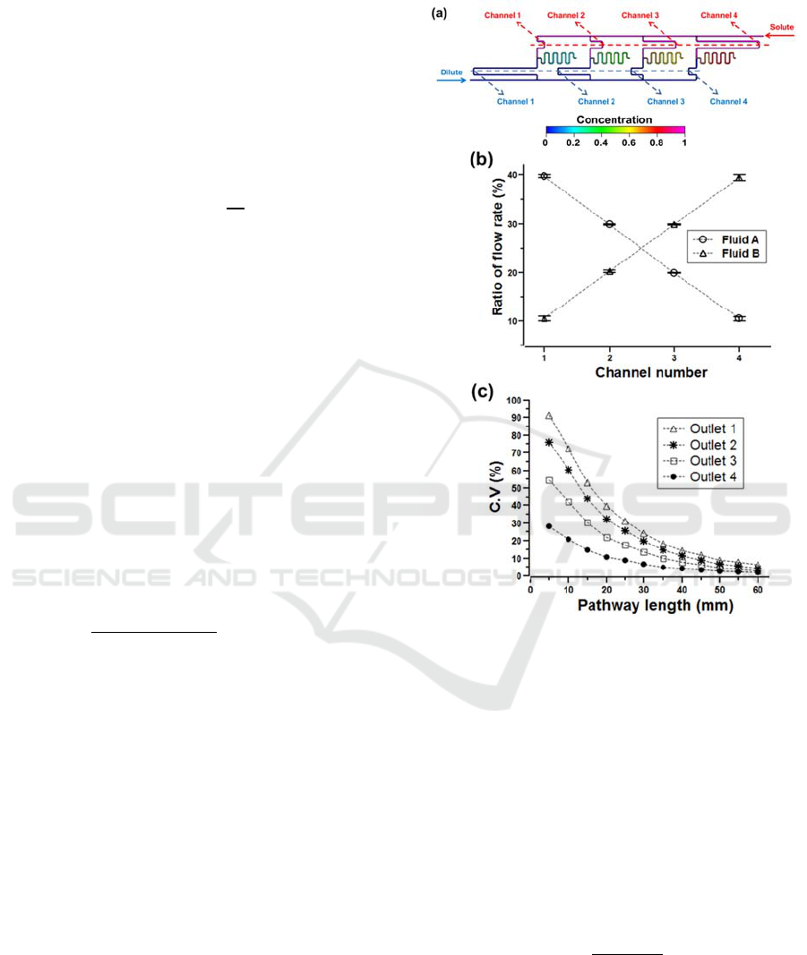
microchannel mixers with a length of 60 mm. Figure
2 shows the linear concentration gradient generator
with ratios of 39.7%, 29.9%, 20.0% and 10.4%. The
error was evaluated to be less than 4% compared
with the design values.
2.3 Sudden Expansion Reservoir
When air bubbles adhere onto the surface of the
microchannels, the designed flow resistance in the
concentration gradient generator couldn’t be kept
their designed value. The sudden expansion
reservoir is a cylindrical shape’s chamber collecting
or trapping air bubbles before their entering into the
microchannel. When air bubbles existed in the
samples
injected through the inlet and reached into
Figure 2: Numerical analysis of the perfusion microfluidic
channel. (a) The concentration gradient generator
integrated with microchannel mixers, (b) linear
distribution of flow rates, (c) coefficient of variations.
the reservoir, they rise due to buoyancy resulting
from the difference in density. To trap air bubbles in
the reservoir, the rising velocity must be higher than
perfusion velocity. The rising velocity of an air
bubble can be calculated from the balance between
the buoyancy force and the drag force acting on the
air bubble expressed in Eq. 4. (Zheng and Yapa,
2000) and the perfusion velocity is also obtained by
dividing the perfusion flow rate with the cross-
sectional area of the channel.
=
∆
(4)
where,
is the rising velocity of a bubble,
∆ is a difference of density between the
surrounding fluid and the bubble,
is a
diameter of the bubble and is the dynamic
3D Microfluidic Perfusion Cell Culture System for Concentration Gradient and Air Bubble Trapping Functions
201

viscosity of a fluid. From the inequation between the
rising velocity and perfusion velocity, the diameter
of a rising bubble,
can be expressed in Eq. 5.
=
∆
(5)
where, is an area of the cross-sectional plane.
In the perfusion flow condition used for numerical
analysis of the concentration gradient generator, the
minimum diameter of rising bubbles was 8 μm and
bubbles with below 8 μm of diameter is negligible
for clogging microchannel with 0.5 mm of width and
2 mm of depth. Figure 3 shows the behaviour of air
in the sudden expansion reservoir was simulated in
2-dimensional structure. The transient analysis
showed that the air bubbles in the reservoir collected
as much as approximately 55.7 mm
2
, and the
reservoir capacity was 60 mm
2
. This implies that the
trapping capacity of air bubbles is almost equal to
the volume of the sudden expansion reservoir.
Figure 3: CFD simulation of behaviour of air bubbles in
the 2D sudden expansion reservoir.
The reservoir was an elliptic shape with a major
length, minor length and height of 10, 5.5 and 6 mm,
respectively. The trapping capacity of the reservoir
was 260 μl.
3 FABRICATION OF THE 3D
MICROFLUIDIC PERFUSION
CELL CULTURE
The 3D microfluidic perfusion cell culture well plate
was fabricated by using a milling machine and
bonding two plates of biocompatible and transparent
PMMA. The four cell culture wells were fabricated
with the same size as those in the general 2D 3×4
well-plate. Additionally, the size and shape of the
wells were fitted to the scaffolds for the 3D culture
of cells. At the centre of the bottom of each well, a
hole was bored to supply media continuously. The
open drain channel was machined at top side of
wells with an inclined angle of 7
o
to guide the
overflown media from the perfusion culture wells by
gravity.
The linear concentration gradient generator
connected with the meandered microchannel mixers
was machined in the bottom perfusion channel plate.
To bond the well plate and the channel plate, a
transparent and UV curable adhesive (MP-4102,
CALO®) was coated onto the bottom of the upper
well plate. After the outlets of the microchannel
mixers were aligned with the holes of the culture
wells and the two plates were bonded physically,
UV was irradiated onto the edges for 5 seconds at 9
Watt and onto the whole surface for 30 minutes at 9
Watt.
Figure 4 shows the fabricated 3D microfluidic
perfusion cell culture plate. To evaluate the bonding
quality, the blockage of the microchannels due to
adhesive filling and the leakage of the unbound parts
were examined. When water was introduced with a
large flow rate of 500 μl/min, no local blockage was
observed in the microchannels.
Figure 4: The 3D perfusion cell culture plate fabricated
from PMMA.
4 EXPERIMENTS
4.1 Performance Evaluation of the
Microfluidic System
4.1.1 Concentration Gradient Generation
The perfusion flow rate injecting into the 3D
microfluidic perfusion cell culture plate was
controlled by a syringe pump (PHD 2000, Harvard).
First, the concentration gradient generator was
examined. Deionized (DI) water dissolved with
rhodamine-110 molecules was injected into one inlet
while only DI water was injected into the other inlet.
To obtain a reference in fluorescence intensity
versus concentration, rhodamine-110 with a
controlled concentration ranging from 0.0 to 18.7
μg/ml was prepared as shown in figure 5. The
fluorescence intensity of Rhodamine-110 was
measured for the different concentrations with a
BIODEVICES 2019 - 12th International Conference on Biomedical Electronics and Devices
202
microplate reader (FLUOstar, OPTIMA). The
calibration curve was fitted with an R
2
of 0.9820
shown in figure 5. The inlet flow rate of two samples
was 80 μl/min. The syringes were refilled every 6
hours and three times. During the refilling process of
the water, the air bubbles moving into the perfusion
microchannel were observed. The samples with
volume of 150 μl in each well were taken every 30
minutes. Then the fluorescence intensity of the
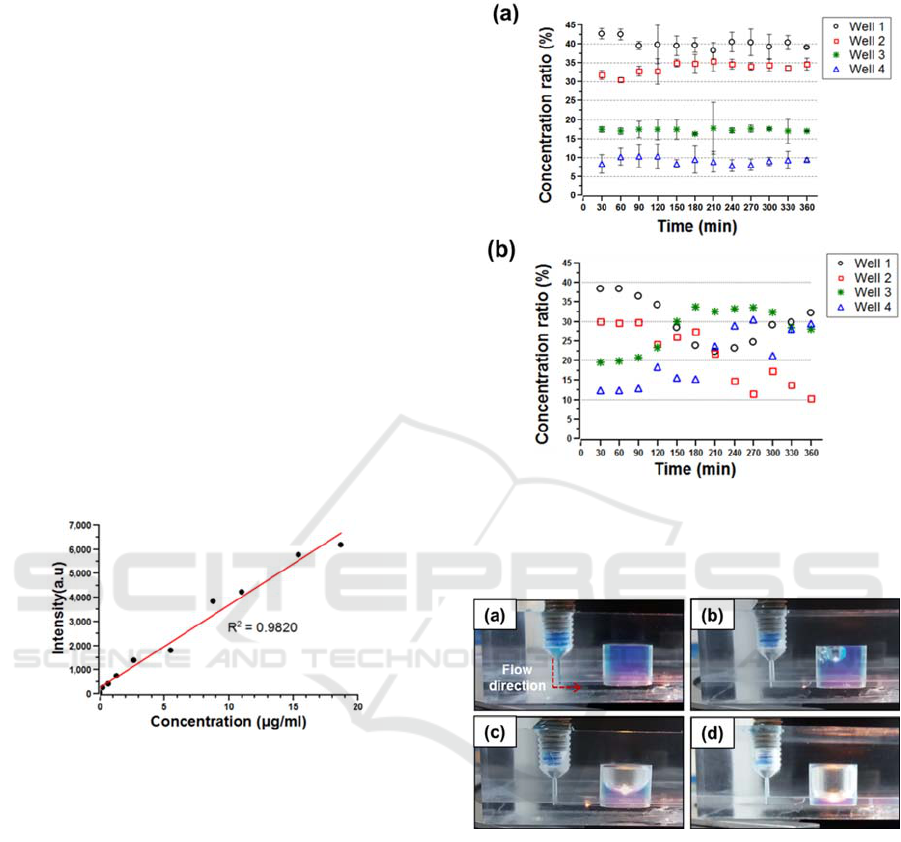
samples was measured. Figure 6(a) shows that the
linear concentration gradient of 40%, 30%, 20% and
10% in the four perfusion wells was generated with
an error of 9.7%. The C.V. was calculated to be
1.9% on average by taking samples several times
shown in figure 6(a). Moreover, the performance of
the linear concentration gradient generator was
tested without the air bubble trapping reservoirs. As
soon as air bubbles were introduced into the branch
microchannels, the flow entering the linear
concentration gradient generator was seriously
disturbed and detoured into the rest of the branch
microchannels. As a result, the linear concentration
gradient was no longer consistently maintained
shown in figure 6(b).
Figure 5: Calibration of rhodamine-110 concentration to
fluorescent intensity.
4.1.2 Air Bubble Trap
The trapping capacity of the air bubble trap reservoir
was tested. Initially, the 3D microfluidic perfusion
cell culture plate was filled with blue coloured water
for visualization. Then, air in a syringe was injected
with a flow rate of 50 μl/min. The trapping of the air
bubbles in the reservoir was monitored over time.
Figure 7 shows that the air in the reservoir was
trapped due to buoyancy. The trapping capacity of
the reservoir was measured when the air bubbles
started to enter into the microchannel. It was
measured to be 268 μl, which agrees well with the
designed capacity. The small discrepancy was
caused by the extra volume as a result of the
meniscus of the air bubble.
Figure 6: Concentration gradient of rhdamine-110
generated in 3D microfluidic perfusion cell culture plate.
(a) Perfusion test with sudden expansion reservoir, (b)
without reservoir.
Figure 7: Visualization of trapping air bubbles in the
sudden expansion reservoir. (a) The reservoir filled with
blue coloured water, (b)-(d) injecting air, (d) limitation of
trapping air bubbles.
4.2 Cell Cytotoxicity Test
The 3D microfluidic perfusion cell culture plate was
used for a cytotoxicity test of Ewing’s sarcoma cells,
A-673 (ATCC® CRL-1598™), which are rare
tumour cells and mostly expressed in the bones or
tissues of children. It is not clearly known what
causes Ewing’s sarcoma. However, experimental
reports have shown that the concentration of
hydrogen peroxide, H
2
O
2
, has a key role in cancer
development (Lopez-Lazaro, 2007). Thus, the
3D Microfluidic Perfusion Cell Culture System for Concentration Gradient and Air Bubble Trapping Functions
203

toxicity test of the cells used different concentrations
of H
2
O
2
as a cytotoxic drug.
For the 3D cell perfusion cell culture, scaffolds
were inserted into the four perfusion wells, and the
Ewing’s sarcoma cells were seeded onto the
scaffolds. Then, to mimic an in vivo environment,
the media were warmed in a water bath, and the
temperature was maintained 36
o
C. Moreover, the
3D perfusion cell culture plate was installed in a
warm chamber to acclimate it to a temperature of 36
o
C. By using a peristaltic pump (MNI PULS 3,
Glison®), the nutrient medium and a mixture of the
medium and H
2
O
2
were introduced into the two
inlets, respectively, and the perfusion flow rate was
40 μl/min for each. Specifically, the perfusion flow
rate was selected by considering the designed linear
concentration gradient generator in the four culture
wells and the previous work using a perfusion cell
culture with a perfusion flow rate ranging from 0.1
to 1 ml/min (Cartmell and Porter, 2003)
The perfusion cytotoxicity was assayed for 4
hours. During this time, 100 μl of drained media
were collected every 30 minutes and mixed with 10
μl of propidium iodide (PI). Then, the fluorescence
intensity was analysed. The excitation and emission
wavelengths were 540 and 620 nm, respectively.
The gain value was set as 1800. The intensity of the
PI relates the degree of cell death. The degree of cell
death was measured for the four different
concentrations of H
2
O
2
. Figure 8 shows that cell
death increased continuously until up to 240 minutes,
while the specific threshold concentration of the cell
death was not found. Moreover, more cells were
killed at the higher concentration. A higher PI signal
was observed at a higher concentration of H
2
O
2
, and
there were less cell proteins on the scaffold. To
conduct long-term culture assays using the perfusion
cell culture system, the 3D microfluidic perfusion
cell culture plate needs to increase its capacity for air
bubble trapping, after which, it needs to be
compared with a 2D static cell culture of the same
cells.
5 APPLICATION OF THE 3D
MICROFLUIDIC PERFUSION
SYSTEM
In this study the 3D microfluidic perfusion cell
culture plate with a 4 fold dilution of concentration
gradient is presented. The designed 4 fold dilution of
screening shows the feasibility of our design and
application to cell culture processes. Even though
the well size is similar to the general 3×4 well-
Figure 8: Result of PI stained DNAs from Ewing’s
sarcoma cells.
plate’s one, the structure is quite different size with
the general 3×4 well-plate. Most microplate reading
tools are for fixed to general well-plate size, so the
well-plates can be inserted on the reading tools
directly. Thus, the structure is improved to have
similar size with the general 3×4 well-plate for
simplifying cell culture processes, increasing high-
throughput rate of sample screening as well as
compatibilities with general measuring tools as
shown in figure 9.
The concentration range is expanded from a 4
fold dilution of 10-40% to a 100 fold dilution of 1-
100% based on the design. Figure 10 shows the
detail concentration gradient for 7 wells with a
hundred fold dilution and figure 11 shows a
performance of generating concentration gradient by
injecting rhodamine-110 into the improved 3D
microfluidic perfusion well-plate. From the result of
perfusion of rhodamine-110 in the improved well-
plate, after 30 minutes of perfusion the intensity
corresponding to concentration of rhodamine-110 is
close to reference samples, which are concentration
fabricated manually to comparison with perfusion
sample.
The system performance is expected to be stable
by connecting three sudden expansion reservoirs in a
row at each inlet side.
Polycarbonate is chosen for fabrication of the
improved 3D perfusion well-plate considering the
biocompatibility and feasibility of autoclave
sterilizations.
BIODEVICES 2019 - 12th International Conference on Biomedical Electronics and Devices
204

Figure 9: Improved 3D microfluidic perfusion well-plate.
Figure 10: Result of numerical analysis of expanded
concentration gradient range.
Figure 11: Fluorescent intensity with a concentration of
rhodamine-110.
6 CONCLUSIONS
A 3D microfluidic perfusion cell culture system
consisting of concentration gradient generators to
provide a linear concentration integrated meandered
micromixers for nutrients or drugs and air bubble
trapping reservoirs was developed in this study to
examine cell cultures with a closer relevance to in
vivo microenvironments.
The performance of the concentration gradient
generator connected with the microchannel mixer
was designed by considering flow resistances of
microchannels and examined by measuring the
fluorescence intensity of rhodamine-110 in the
perfusion cell culture wells. The linear concentration
in the wells had a 4 fold of dilution. Additionally,
the trapping capacity of the sudden expansion
reservoir for air bubbles was determined by transient
numerical analysis and visualization. Both methods
showed that the incoming air bubbles float upward
in the sudden expansion trapping reservoir due to the
buoyancy force and gathered until the reservoir was
full. The maximum trapping capacity of the
reservoir was determined to be the same volume as
the sudden expansion reservoir. In addition, the
linear gradient concentration in the wells was stably
maintained for a long-term cell culture with the air
bubble trapping reservoir, while the concentration in
the wells without it was seriously disturbed.
Finally, the 3D microfluidic perfusion well-plate
was improved for compatibilities with measuring
tools like microplate-readers increase of high
throughput rate by expanded concentration range
from a 4 fold of dilution to a 100 fold dilution. Also,
the improved well-plate was fabricated from
polycarbonates for the biocompatibility and
processing the autoclave sterilization.
The suggested 3D microfluidic perfusion cell
culture plate is potentially applicable to high
throughput screening of drugs, nutrients, and growth
factors. For future works, its comparison with a 2D
static cell culture well plate should be done for a
specific targeted cell.
ACKNOWLEDGEMENT
This work was supported by the National Research
Foundation of Korea (NRF) grant funded by the
Korea government (MSIP) (No.
2017R1A2B2006264).
REFERENCES
Schumacher, K., Strehl, R., 2012. Advanced Technique
for Long Term Culture of Epithelia in a Continous
Luminal-Basal Medium Gradient. Biomaterials.
Caicedo-Carvajal, C., Liu, Q., 2011. Cancer Tissue
Engineering: A Novel 3D Polystyrene Scaffold for In
Vitro Isolation and Amplification of Lymphoma
Cancer Cells from Heterogeneous Cell Mixtures.
Journal of Tissue Engineering.
Baker, B., Chen, C., 2012. Deconstructing the Third
Dimension – How 3D Culture Microenvironments
Alter Cellular Cues. Journal of Cell Science.
Li, X., Valadez, A., 2012. Microfluidic 3D Cell Culture:
Potential Application for Tissue-Based Bioassays.
Bioanalysis.
3D Microfluidic Perfusion Cell Culture System for Concentration Gradient and Air Bubble Trapping Functions
205

Caicedo-Carvajal, C., Liu, Q., 2012. Using a Novel 3D
Perfusion bioreactor to Culture β-actin-RFP Reporter
Osteosarcoma. Biowire Spring.
Ong, S., Zhang, C., 2008. A Gel-Free 3D Microfluidic
Cell Culture System. Biomaterials.
Yi, L., Lin, J., 2017. Development and Applications of
Microfluidic Devices for Cell Culture in Cell Biology.
Molecular Biology.
Langelier, S., Livak-Dahl, E., 2011. Flexible Casting of
Modular Self-Aligning Microfluidic Assembly Blocks.
Lab on a Chip.
Sung, J., Shuler, M., 2009. Prevention of Air Bubble
Formation in a Microfluidic Perfusion Cell Culture
System Using a Microscale Bubble Trap. Lab on a
Chip.
Nguyen, N., Wereley, S., 2006. Fundamentals and
Applications of Microfluidics, ARTECH HOUSE.
Boston, London, 2
nd
edition.
Zheng, L., Yapa, P., 2000. Buyant Velocity of Spherical
and Non-Spherical Bubbles/ Droplets. Journal of
Hydraulic Engineering.
Lopez-Lazaro, M., 2007. Dual Role of Hydrogen Peroxide
in Cancer: Possible Relevance to Cancer
Chemoprevention and Therapy. Cancer Letters.
Cartmell, S., Porter, B., 2003. Effects on Medium
Perfusion Rate on Cell-Seeded Three-Dimensional
Bone Constructs in Vitro. Tissue Engineering.
BIODEVICES 2019 - 12th International Conference on Biomedical Electronics and Devices
206
