
Geolocalization in Smart Environment
Joseph Merhej
1
, Jacques Demerjian
1
, Karla Fares
1
, Jacques Bou Abdo
2
and
Abdallah Makhoul
3
1
LARIFA-EDST Laboratory, Faculty of Sciences, Lebanese University, Fanar, Lebanon
2
Department of Computer Science, Notre Dame University, Deir el Qamar, Lebanon
3
FEMTO-ST Institute, University of Bourgogne Franche-Comté, Belfort, France
Keywords: Wireless Sensor Network, Collaborative Wireless Sensor Network, Localization, RSSI, Ultrasound.
Abstract: Nowadays, wireless indoor positioning systems have become very familiar, and widespread all over the world.
They are successfully used in many applications including tracking objects e.g. Firemen who usually face
life-threatening situations. Indoor positioning systems become critically convenient in such scenarios. This
paper deals with the tracking of a group of firemen during their mission in order to have a real-time visibility
of their coordinates. These firemen are armed by smart sensors and are, at the same time, active in a smart
environment containing referenced nodes. This paper will propose two approaches: ‘Centralized Emission’,
and ‘Broadcast Emission’ and will describe the proposed method to calculate the firemen’s coordinates.
1 INTRODUCTION
Sensors have recently played an important role in
monitoring objects in a specific environment. These
sensors are small in size, have low power
consumption, and can be easily integrated into a
network to create a Sensor Network. Wireless Sensor
Network (WSN), a set of distributed devices / sensors
used to monitor the environment, also uses a gateway
providing wireless connection. By enhancing
technologies, sensors will have the ability to
cooperate and exchange information between each
other, so that WSN becomes Collaborative Wireless
Sensor Network (CWSN). Wearable Sensor Network
is a special case of CWSN, where the sensors are
mounted on/worn by individuals.
Nodes cooperate to solve the problem of tracking
objects and people. Many techniques and methods are
used to compute the position of an object in its
environment. This process is called “localization”.
This paper concentrates on localization in WSN
and CWSN. The localization of sensors in a
WSN/CWSN faces many problems such as the
complexity/topology of the network itself, the signal
propagation, the reflection problems, the obstacles,
etc.
The localization problem has been studied
thoroughly in literature and many algorithms were
proposed to resolve the complexity of the localization
problem.
Our study on WSN in the localization field, can
be used in different scenarios to track the localization
of people or devices (firemen, policemen, soldiers,
vehicles, etc.) during their works. Saving lost person
or device requires locating him first and this is the aim
of this work. Our study will treat the case of localizing
firemen moving in an indoor environments, with
emergent obstacles i.e. The obstacles’ positions are
predefined. Many problems faces our study to
calculate the coordinates of each node/device in such
a mobile, distributed, dynamic, and complex network.
Because our study deals with indoor localization
environment, some existing techniques like Global
Positioning System (GPS) are not suitable, and that is
why some other techniques will be used as described
in this paper.
Our approach proposes ‘Centralized Emission’
and ‘Broadcast Emission’ used to calculate the
coordinates of the mobile nodes according to a
beacon (fixed node). In the ‘Centralized Emission’,
each node sends a request to its corresponding beacon
which computes the coordinates of the emitter node
and sends the computed coordinates to a controller
beacon. On the other hand, in the ‘Broadcast
Emission’, each node sends its request to the beacon
and all its neighbors existing in its range. Once the
request is received, the beacon computes the
coordinates of each node and sends it to the controller
beacon.
The remaining of this paper is organized as fol-
108
Merhej, J., Demerjian, J., Fares, K., Abdo, J. and Makhoul, A.
Geolocalization in Smart Environment.
DOI: 10.5220/0007472601080115
In Proceedings of the 8th International Conference on Sensor Networks (SENSORNETS 2019), pages 108-115
ISBN: 978-989-758-355-1
Copyright
c
2019 by SCITEPRESS – Science and Technology Publications, Lda. All rights reserved

lows: Section II presents the computing techniques
and methods used to localize a target. Section III
illustrates the state-of-the-art proposals and describes
the existing systems for Indoor Positioning Systems
(IPS), their advantages, and disadvantages. Section
IV discusses our approach to estimate the localization
in a Wearable Sensor Network. Finally, Section V
summarizes the paper.
2 LOCALIZATION METHODS
AND TECHNIQUES
In this section, we describe various measurement
methods and localization techniques used by existing
CWSN indoor localization algorithms (Zhang, 2010).
2.1 Measurement Methods
2.1.1 Time-Of-Arrival (TOA)
The distance between the transmitting node and the
receiving one is deduced from the transmission time
delay and the corresponding speed of signals. The
distance can be calculated as follows
R=Time*Speed
Where R is the distance between the sender and the
receiver, Speed is the signal’s traveling speed and
Time is the amount of time spent by the signal
traveling from the sender to the receiver. A
combination of TOA and Ultra Wide Band (UWB)
has been used to guarantee a higher precision (Falsi,
2006), because TOA technique has a restrict
requirement of synchronization, this inefficiency can
be resolved by UWB that uses short pulse duration to
filter out the signals caused by reflections (Cheong,
2005).
2.1.2 Time-Difference-Of-Arrival (TDOA)
This method uses two kinds of radio transmitting
signals. The time difference between these two kinds
of signals is used to reconstruct the transmitting
node’s position. The equation is:
21
21
tt
C
R
C
R
Where C1 is the speed of one kind of radio signals,
C2 the speed of another kind of radio signals, t1 and
t2 are the time for these two signals to travel from one
node to another, R is the distance between sender and
receiver. The author of (Takabayashi, 2008) uses the
Time Difference of Arrival (TDOA) method with
Extended Kalman Filter (EKF), and this approach is
suitable in environments where the number of
beacons is not sufficient.
2.1.3 Round Trip Time (RTT)
This method solves the problem of synchronization
incurred by the use of TOA method (Mailaender,
2007). The equation is:
2
*)( speedt
RT
t
R
t
RT
is the time needed for a signal to travel from one
node to another and back again, ∆t is the time delay
required by the hardware to operate at the receiving
node, while speed is the speed of the transmitting
signal.
2.1.4 Angle-Of-Arrival (AOA)
The authors of (Linde, 2006) (Niculescu, 2003)
determine the direction of propagation of a radio-
frequency by measuring the TDOA at individual
elements of the array antennas. Consequently, the
AOA can be calculated. Therefore, no time
synchronization between nodes is required.
2.2 Localization Techniques
2.2.1 Trilateration
It uses three fixed non-collinear reference node to
calculate the position of a target node (in 2D) as
shown in Fig 1. Authors of (Han, 2007) confirmed
that trilateration can best demonstrate its advantages
when the three reference nodes are deployed as
equilateral triangle.
R
yyxx
R
yyxx
R
yyxx
2
3
)()(
2
2
)()(
2
1
)()(
2
3
2
3
2
2
2
2
2
1
2
1
Figure 1: Trilateration–based Positioning.
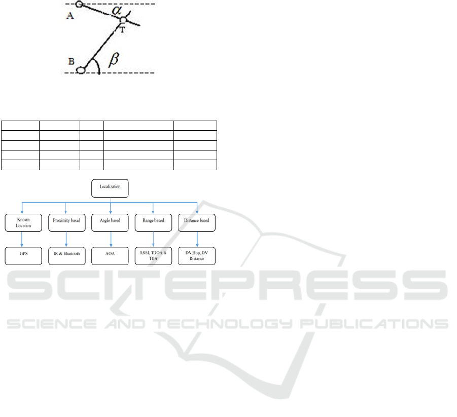
2.2.2 Triangulation
The position of a target node can be obtained by the
intersection of several pairs of angles direction lines.
Compared to trilateration only two reference nodes
can track the target as shown in Fig 2. The
Geolocalization in Smart Environment
109
comparison between the different measurement
methods will be clearly shown in Table 1.
Figure 2: Triangulation-based positioning.
Table 1: Comparison Between Different Methods.
Methods Accuracy Cost Energy Efficiency Size of HW
TOA
Medium High Low Large
TDOA
High
Low High Large
AOA Low High Medium Large
RTT
High
High High Large
Figure 3: Localization-based Techniques.
3 RELATED WORK
Several studies tackled the problem of localization to
estimate the coordinates of each node/device in a
complex network. In this section, we will cover with
more details the recent and existing algorithms for
Indoor Positioning System (IPS) and show their
advantages and disadvantages as well.
The Active badge (Want, 1992) (Harter, 1994) is
used to locate individuals in a building. It estimates
their location based on their badges that transmit a
unique infra-red signal every 15 seconds, and each
room in the building is equipped with a network of
sensors which detects these transmissions. The
location can be determined according to the
information delivered by these sensors. The
advantage of this algorithm is the privacy of the
address, whereas its disadvantages are the low
accuracy, long transmission period, and the
influences from fluorescent light and sunlight.
Based on the IR technique, the Firefly system
(Firefly Motion Capture System, 2008) (Firefly
Motion Tracking System User's guide, 1999) comes
with a controller tag, and other several tags in
addition to one array of cameras, is used to track a
person’s or vehicle’s motion. The tag controller
which is carried by the tracked person, is small in size,
light in weight, and battery equipped. Tags are IR
emitters and mounted on different tracked parts of the
person. The array camera receives the IR signals sent
by tags fixed on different parts of the person and
estimates his 3D position. The advantage of this
algorithm is the small measurement delay of 3ms
whereas its disadvantages are that it uses a wire to
connect tags and the coverage area is limited to 7m.
The Optotrak algorithm (Optotrak, 2008) (States,
2006) uses three cameras as a linear array to track 3D
position of various markers on an object. The markers
mounted on different parts of a target, and emit IR
light that is detected by the cameras to estimate their
position. The system uses the triangulation technique
to estimate the position. The advantage of this
algorithm is the high accuracy which is able to
manage relative motion on the different parts of an
object but it is limited to line-of-sight requirement.
The IRIS-LPS approach (Aitenbichler, 2003) is an
optical IR local positioning system. Stereo-Cameras
receive IR signals from a tag mounted by a target
object to measure the AOA, and calculate the position
of the tag using triangulation technique. The main
advantage of this approach is the coverage area it has,
which is larger than that of Firefly and Optotrak, in
addition to this, it is cheap and easy to be installed and
maintained. Moreover, the IRIS-LPS is a multi-tag
track approach but it is subject to interference from
florescent light and sunlight.
The Active Bat system (Active Bat, 2008) (Ward,
1997) uses Ultrasonic technology and triangulation
technique to measure the location of the tag carried
by a person. Tags broadcast periodically a short pulse
of Ultrasound that is received by a matrix of ceiling
mounted receivers at known positions. The distance
between a tag and three receivers is needed to
calculate the 3D position of the tag based on the
multilateration principle. The main advantage is that
it covers a large area and provides 3-D positioning,
but it is subject to the reflection of obstacles and it
uses a large number of receivers on the ceiling.
The Cricket algorithm (Priyantha, 2000) (Das,
2005) uses TOA measuring method and triangulation
technique to locate a target. It uses an ultrasound
emitter as infrastructure, and a receiver carried on
each target. The target owns its location information
and decides how to publish it. The emitters also
transmit RF messages in order to synchronize the
TOA measurement. Its advantages are the address
privacy, the low cost, and the decentralized
administration, but it has high energy consumption.
The Sonitor algorithm (Sonitor, 2008) can locate
SENSORNETS 2019 - 8th International Conference on Sensor Networks
110

people and devices in real time. In the ultrasound IPS,
tags attached to people are tracked by a wireless
detector fixed in various places in an indoor area. The
tracked tag transmits ultrasound signals with a unique
identifier; once received by a detector in the same
place, the detector forwards the information through
the existing LAN or WLAN to a central positioning
calculation element. Its advantage is energy
efficiency though it has a low accuracy level.
The WhereNet algorithm (WhereNet, 2008) is a
Real Time Location Systems (RTLS). It has tags,
location antennas, location processors, servers, and
Ports. Tags are attached to their objects like
persons/devices. Location antennas mounted on the
ceiling at fixed positions receive the signals emitted
from tags and forward the data to the location
processor that perform location calculation and can
track many tags at the same time. Finally, the location
processor transmits the tags’ positions to the server
where ports send low frequency electromagnetic
signals to the tags to indicate their behaviors. The
advantage of this process is the uniquely identified
equipment and person. But it needs several
infrastructure components.
The RADAR algorithm (Bahl, 2000) uses the
existing WLAN, signal strength and signal-to-noise
ratio with the triangulation technique. It can provide
2-D absolute position information. The advantage, is
the reuse of the existing WLAN infrastructure but it
has a low accuracy level, and no privacy
consideration. The located node needs to be equipped
with WLAN technique which is difficult to be applied
because the locate node is light in weight, and has a
limited time energy.
The EKAHAU algorithm (Ekahau, 2008) uses the
existing indoor WLAN infrastructure to monitor the
motion of Wi-Fi tags. The triangulation technique is
used to locate any Wi-Fi enabled device, while the
RSSI values of the transmitted RF are used to
determine the location of the devices. This system
offers 2-D position information. The advantage is the
low cost and power level of the battery but it has a
low level of accuracy because it needs a lot of
calibration, it can only provide 2-D location
information. The comparison between the described
algorithms is presented in Table 2.
In (Ahmadi, 2017), the authors mentioned that
RSSI is widely used because of its availability in most
wireless devices. They also mentioned that range-
based localization category (e.g. AOA, TDOA,
UWB) are expensive in power and delay; while
range-free localization (e.g. neighborhood, and hop)
have limited accuracy. So, they proposed a new
algorithm that merges the learning regression tree
approach with filtering method using RSSI metrics.
Based on artificial intelligence, the learning tree is
used to estimate the position of a mobile device, then
an advanced Particle Filter (PF) is used to minimize
the error of the estimated computed position. The
experience shows that the proposed algorithm is
accurate, and robust to environmental change. In
addition, the PF is robust to noisy environment and
has a low error localization.
In order to reduce the cost of Indoor Localization
Systems (ILS), the authors of (Li, 2018) proposed
PLILS based on a cheap and widely used commercial
chip which supplies four discrete power levels. The
localization employs the idea of fingerprint. PLILS
consists of one reader, reference nodes, and mobile
target nodes. Every reference node broadcasts a data
packet (data fields, identity, etc.) periodically, the
target nodes will receive, process the broadcast
packets, create one specific form, and send it to the
reader for positioning themselves. In addition, to
avoid the large localization errors, a new algorithm
called SOM is used to divide the constructed map of
the target region into several sub-regions. This cost-
effective approach has an accuracy of 1m. Other
studies reached a minimum accuracy of 2m such as in
(Gunathillake, 2016),
4 OUR APPROACH FOR
LOCALIZATION IN
WEARABLE SENSOR
NETWORK
Nowadays, the concept of a smart building is in a
perpetual progress. Many studies were done on the
core of this topic. Our approach will use this concept
in dealing with localization in a Wearable Sensor
Network. The plan of this smart building will be
composed of sensors having a defined range of
capture in predefined areas/locations. Our approach
on localization using Wearable Sensor Network, can
be used by firemen, police, army, etc. Our used
scenario represents a group of firemen during an
indoor firefighting mission. The target is to have a
real-time visibility of the status of each fireman
specially his location, by calculating the coordinates
(X, Y) of each fireman (node) in such mobile
(variable node), distributed (the nodes are in many
places within the environment), dynamic (many
nodes can be added or removed from the network)
and complex network.
Geolocalization in Smart Environment
111

Table 2: Description and Comparison Between Different
Existing Algorithms.
System
Name
Accuracy
Security &
Privac
y
Cost
Technology/
Method
Active
Badge
Room
Level
No
Reasonable price
with cheap tag and
sensors
Ultra-sound /
RSS
Firefly 3.0 mm No
A tag controller and
32 ta
g
s
Infrared / Not
available
Optotrak 0.1-0.5 mm No Expensive
Infrared / Not
available
IRIS-LPS
16 cm out
of 100 m²
No
Less than Firefly
and
Optotra
k
Infrared /
Triangulation
Active Bat
3 cm out
of
1000 m²
No Expensive
Infrared /
Multilateratiom
Cricket 10 cm Yes Cheap
Ultra-sound,
RF / TOA and
Trian
g
ulation
Sonitor
Room
Level
No Cheap
Ultra-sound /
Not available
WhereNet
2 to 3 m
No Ex
p
ensive RFID / TDOA
RADAR
2.26 m out
of 213
m
2
No
Research-oriented
solution, no
p
roducts
WLAN /
Trian
g
ulation
EKAHAU 1
m
No Chea
p
WLAN / RS
As mentioned in the previous section, many
algorithms and methods were proposed and discussed
in order to track and compute the position of a target
in indoor environment. Existing algorithms are based
on one or more technology such as RF, RSS, UWB,
WLAN, Bluetooth, etc. and many other computing
methods like TOA, TDOA, RTOA and AOA, etc.
These proposed algorithms had their conveniences
and inconveniences according to the used network,
technologies, and methods.
WLAN (IEEE 802.11) is very popular in public
hotspots and enterprise locations. During the last few
years, it has a high rate of 11.54 to 108Mbps, and a
range of 50 to 100m, and an update rate of a few
seconds. IEEE 802.11 is the dominant WLAN. Many
algorithms based on WLAN (RADAR, DIT, etc.) or
Bluetooth (Topaz that integrate IR with the Bluetooth
positioning and communication) seems to be suitable
for our approach but the limitation of these algorithms
is their low-ability to overpass obstacles.
The Bluetooth (IEEE 802.15) technology is
suitable for our approach because it is highly
ubiquitous (embedded in many devices) and it can
support many other networking services. Moreover,
Bluetooth tags are small sized transceivers, and have
a unique ID that can be used to locate each tag.
Bluetooth was designed to exchange a lot of data at
close range. In 2011, when the Bluetooth Low Energy
(BLE) was developed, it had the advantage of low
power consumption but with lower bandwidth, so it
can be largely used for a device that exchanges a
small amount of data periodically which is more
suitable in our case in both proposed scenarios
(Centralized and Broadcast emissions), the range of
this device is about 100 m but it depends on the
surrounding, radio performance, and antennas. The
comparison between Bluetooth and Bluetooth Low
Energy will be described in Table 3.
As mentioned by the authors of (Piwowarczyk,
2013) and (Zhou, 2010), the placement of the beacons
can influence the accuracy of the localizations, that’s
why we suggest to use flexible beacons that can rotate
around their axes in order to have a wide area of
coverage, so that we reduce the repetition of signals
request. As a result, this method will reduce the
energy consumption, the network traffic, and the re-
computation of the localization position. In fact,
recent study demonstrates that the transmission
power of the BLE beacons has a significant impact
on the overall range of the beacons, it is assumed that
adjusting the transmit power of the BLE beacon has
an effect on the beacon’s range and their ability to
overpass obstacles such as walls. Our approach will
use the following technologies:
BLE having the advantage of low power
consumption.
Flexible beacons having the ability of rotating
around their axes for better visibility.
Enhancing the transmission power of the BLE
beacon to increase its ability to overpass obstacles
such as walls, but this overpass will affect the
accuracy in positioning the tags.
Table 3: Comparison between Bluetooth V2.1 and BLE.
Bluetooth V2.1
Bluetooth Low Energy
(BLE)
Ran
g
e
Up to 100m Up to 100m
Max range
(free field)
Around 100m
(Class 2 outdoor)
Around 100m
(Outdoors)
Fre
q
uenc
y
2.402-2.481 GHz 2.402-2.481 GHz
Max data rate
1-3 Mbit/s 1-Mbit/s
Application
throu
g
h
p
ut
0.7-2.1 Mbit/s
Up to 305 Kbit/s
Topologies
Point-to-point,
Scatternet
Point-to-point,
Mesh networ
k
Network
standard
IEEE 802.15.1 IEEE 802.15.1
The simulated environment where the armed
firemen (tag holders) are acting, is composed of a
room (20*20 m) having reference nodes called
beacons that will be able to rotate in a horizontal plan,
a Controller Beacon (CB) that memorizes the
localization of every node within the range of each
beacon. Many characteristics should be taken into
consideration to success our implantation.
Fast: The aim is to have a fast request and
response while emission depends on the mode of
transmission and the used hardware.
Smart: The algorithm should compute and
estimate the position of each node with fewer
errors.
SENSORNETS 2019 - 8th International Conference on Sensor Networks
112

Scalable: The number of nodes is variable so the
network should be able to accept any changes
(adding or removing any node).
To avoid synchronization problem with the beacons,
the CB, in every lap of time, will send a request to all
beacons asking them to get the position of all active
firemen existing in their range.
4.1 Centralized Emission
For the centralized emission, each beacon will send a
signal (RSSI, Ultra-Sound or Radio Frequency
Signal) to all the nodes that are in its range. Once
received, each node will reply by sending the
following information to their related beacon: (Sensor
ID, TOS (Time of Sending), Frequency, Sent flag,
Received flag).
Once the beacon captures the signal, it estimates
the coordinates of the node S (emitter) by using the
Time of Arrival (TOA) and the Angle of Arrival
(AOA) by applying the following formula and as
shown in Fig. 4.
t
f
D
(f: frequency of transmission;
TOSTOAt
)
):(cos AOAD
X
s
sinD
s
Y
Figure 4: Centralized Emission Scenario.
The concerned beacon will send the result to the
CB in order to update its routing table by saving the
computed coordinates of each node referenced by its
ID. Then, it sends a response to the node in question
that updates from its side the flag received and sets it
to ‘True’. By this, it guarantees that the signal is well
captured. The CB will be considered as a reference to
be contacted at any time by the mission’s responsible.
This scenario gives us a real-time visibility about
the coordinates of each beacon with fewer errors, but
on the other hand, it has an inconvenience which is:
once the mobile node is not able to receive a response
from the beacon upon its request because it is out of
the beacon’s range due to its mobility, it is obliged to
resend the request to another beacon and this will
cause a loss of time and energy.
4.2 Broadcast Emission
The same procedure is applied as described in the
centralized emission, but the difference is after
computing the coordinates of the sender, the beacon
will broadcast the information to all other nodes
existing in its range. This scenario will be repeated
every time the beacon computes a new position of the
same node or a new one. It is also repeated by every
beacon. As shown in Fig 5.
This scenario is very efficient and accurate
because any node at any time has the updated
coordinates of all the nodes in the network. As a
result, in both scenarios, the CB will have, at any
time, a general overview of the coordinates of each
node and their related beacon.
Figure 5: Broadcast Emission Scenario.
As a summary, the CB will own in its database a
general table as indicated in the Table 4.
Table 4: Information on a CB about each Target Position
According to each Related Beacon.
Beacon# Ta
g
ID An
g
le X Y Time
1 2 30° 10 8 t1
1 5 30° 20 16 t1
2 7 20° 30 90 t1
1 4 40° 50 70 t2
3 4 40° 60 70 t2
4 1 80° 90 70 t2
………… … …
These two scenarios are suitable for the
characteristics previously mentioned: ‘fast’, ‘smart’
and ‘scalable’ depending on the complexity of the
hardware.
A Matlab simulation shows the number of nodes
covered and tracked by each beacon and shows the
accuracy of our approach. We suppose that we have
20 firemen that are acting randomly in a room (20*20
m) with three obstacles and four beacons as shown in
Fig. 4 and Fig. 5. The beacons had a 30° angle of view
and can rotate horizontally around their axes 30°each
time. The Matlab simulation shows the result and
compares our two scenarios in terms of delay, energy
consumption, tracking, and accuracy as shown in Fig.
6, Fig. 7, Fig. 8, and Fig. 9.
Geolocalization in Smart Environment
113
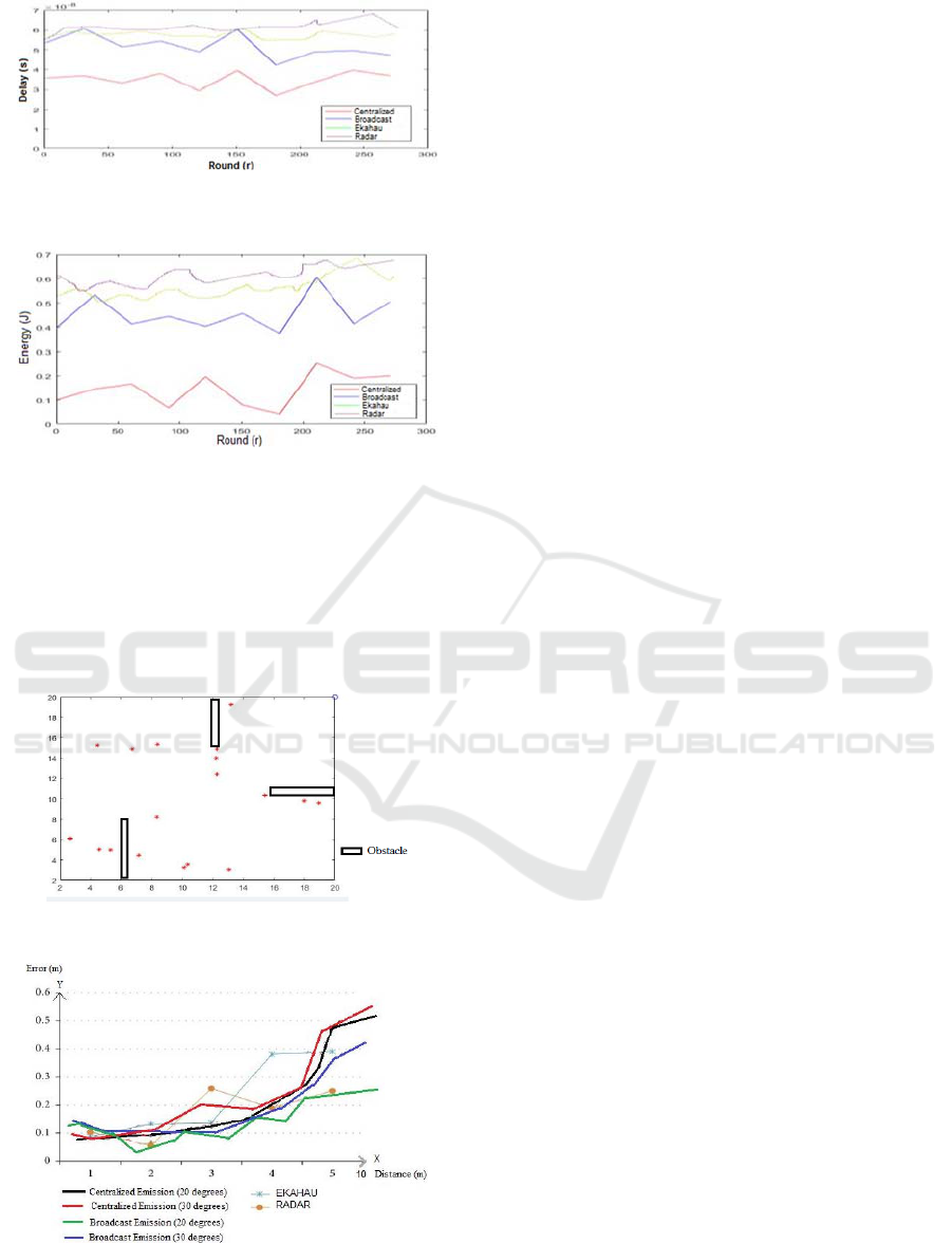
Figure 6: Delay comparison between the centralized and the
broadcast emissions.
Figure 7: Energy comparison between the centralized and
the Broadcast emissions.
As shown in Fig. 8, the number of targets that has
been tracked is 18 whereas the number of firemen was
20. So if we change the parameter of the rotation of
the angle to be 20° at a time instead of 30° and based
on the “broadcast emission”, we can track all the
existing firemen in the environment.
Figure 8: Tracking of the target inside the room.
Figure 9: Accuracy of each scenario and comparison
between our simulation and the RADAR and EKAHAU
one.
As shown in Fig. 9, the X axis represents the
distance between the beacon and the devise existing
in its range. The Y axis represents the errors. We
simulate the accuracy of each proposed scenario
(Centralized and Broadcast). Then, we repeat the
same simulation with a rotation angle of 20 degree.
As a result, the accuracy will increase each time the
rotation angle of the beacons is small. Finally, we
compare our approach in both scenarios with the
Radar’s and EKAHAU’s one. The position will be
more accurate by increasing the number of beacons.
Comparing our algorithm to the existing ones
described in Table 1, we have shown that our
algorithm is more efficient in term of delay (Fig. 6),
energy consumption (Fig. 7), tracking accuracy (Fig.
8 and Fig. 9), and overpassing obstacles based on the
technologies we used (BLE, flexible beacon,
enhancing power transmission).
5 CONCLUSION
In this paper, we discussed indoor localization for
CBSN in smart environment. We proposed 2
approaches a single-hop approach (centralized
emission) and a multi-hop one (Broadcast emission).
The proposed approaches were compared against
existing algorithms on delay, power consumption and
accuracy. Our proposed approaches are very
convenient on power consumption and delay and
have very good accuracy, thus providing a very
competitive alternative.
REFERENCES
Active Bat website 2008 Available:
http://www.cl.cam.ac.uk/research/dtg/attarchive/bat/ .
Ahmadi, H., Viani, F. and Bouallegue, R., 2018. An
accurate prediction method for moving target
localization and tracking in wireless sensor networks.
Ad Hoc Networks, 70, pp.14-22.
Aitenbichler, E. and Muhlhauser, M., 2003, May. An IR
local positioning system for smart items and devices. In
Distributed Computing Systems Workshops, 2003.
Proceedings. 23rd International Conference on (pp.
334-339). IEEE.
Bahl, P. and Padmanabhan, V.N., 2000. RADAR: An in-
building RF-based user location and tracking system. In
INFOCOM 2000. Nineteenth Annual Joint Conference
of the IEEE Computer and Communications Societies.
Proceedings. IEEE (Vol. 2, pp. 775-784). IEEE.
Cheong, P., Rabbachin, A., Montillet, J.P., Yu, K. and
Oppermann, I., 2005, September. Synchronization,
TOA and position estimation for low-complexity LDR
SENSORNETS 2019 - 8th International Conference on Sensor Networks
114

UWB devices. In Ultra-Wideband, 2005. ICU 2005.
2005 IEEE International Conference on (pp. 480-484).
IEEE.
Das, S., Gleason, C., Shen, S., Goddard, S. and Pérez, L.C.,
2005, May. 2d tracking performance evaluation using
the cricket location-support system. In Electro
Information Technology, 2005 IEEE International
Conference on (pp. 6-pp). IEEE.
EKAHAU website 2008 Available:
http://www.ekahau.com/.
Falsi, C., Dardari, D., Mucchi, L. and Win, M.Z., 2006.
Time of arrival estimation for UWB localizers in
realistic environments. EURASIP Journal on Advances
in Signal Processing, 2006(1), p.032082.
Firefly Motion Capture System 2008 [online] Available:
http://www.cybernet.com/interactive/firefly/index.htm
l.
Firefly Motion Tracking System User's guide 1999
Available:
http://www.gesturecentral.com/firefly/FireflyUserGuid
e.pdf
Gunathillake A., V. Savkin A., Jayasumana A. and
Seneviratne A. (2016). Sensor Localization using
Signal Receiving Probability and Procrustes Analysis.
In Proceedings of the 5th International Conference on
Sensor Networks - SENSORNETS, ISBN 978-989-758-
169-4, pages 113-120. DOI:
10.5220/0005671301130120
Harter, A. and Hopper, A., 1994. A distributed location
system for the active office. IEEE network, 8(1), pp.62-
70.
Han, G., Choi, D. and Lim, W., 2007, October. A novel
reference node selection algorithm based on
trilateration for indoor sensor networks. In Computer
and Information Technology, 2007. CIT 2007. 7th IEEE
International Conference on (pp. 1003-1008). IEEE.
Li, X., Yang, Y., Cai, J., Deng, Y., Yang, J., Zhou, X. and
Tan, L., 2018. Plils: A Practical Indoor Localization
System through Less Expensive Wireless Chips via
Subregion Clustering. Sensors, 18(1), p.205.
Linde, H., 2006. On aspects of indoor localization.
Mailaender, L., 2007, September. Comparing geo-location
bounds for TOA, TDOA, and round-trip TOA. In
Personal, Indoor and Mobile Radio Communications,
2007. PIMRC 2007. IEEE 18th International
Symposium on (pp. 1-5). IEEE.
Niculescu, D. and Nath, B., 2003, March. Ad hoc
positioning system (APS) using AOA. In INFOCOM
2003. Twenty-Second Annual Joint Conference of the
IEEE Computer and Communications. IEEE Societies
(Vol. 3, pp. 1734-1743). IEEE.
Optotrak 2008 Available: http://www.ndigital.com/ .
Piwowarczyk, K., Korbel, P. and Kacprzak, T., 2013,
September. Analysis of the influence of radio beacon
placement on the accuracy of indoor positioning
system. In Computer Science and Information Systems
(FedCSIS), 2013 Federated Conference on (pp. 889-
894). IEEE.
Priyantha, N.B., Chakraborty, A. and Balakrishnan, H.,
2000, August. The cricket location-support system. In
Proceedings of the 6th annual international conference
on Mobile computing and networking (pp. 32-43).
ACM.
States, R.A. and Pappas, E., 2006. Precision and
repeatability of the Optotrak 3020 motion measurement
system. Journal of medical engineering & technology,
30(1), pp.11-16.
Sonitor website 2008 Available: http://www.sonitor.com/.
Takabayashi, Y., Matsuzaki, T., Kameda, H. and Ito, M.,
2008, August. Target tracking using TDOA/FDOA
measurements in the distributed sensor network. In
SICE Annual Conference, 2008 (pp. 3441-3446). IEEE.
Want, R., Hopper, A., Falcao, V. and Gibbons, J., 1992. The
active badge location system. ACM Transactions on
Information Systems (TOIS), 10(1), pp.91-102.
Ward, A., Jones, A. and Hopper, A., 1997. A new location
technique for the active office. IEEE Personal
communications, 4(5), pp.42-47.
Wherenet website 2008 Available: http://www.
wherenet.com/.
Zhang, D., Xia, F., Yang, Z., Yao, L. and Zhao, W., 2010,
May. Localization technologies for indoor human
tracking. In Future Information Technology
(FutureTech), 2010 5th International Conference on
(pp. 1-6). IEEE.
Zhou, J., Shi, J. and Qu, X., 2010. Landmark placement for
wireless localization in rectangular-shaped industrial
facilities. IEEE Transactions on Vehicular Technology,
59(6), pp.3081-3090.
Geolocalization in Smart Environment
115
