Design of Microstructure for Stimulating Mechanical Torque to Cells
Hiroaki Nagase and Eiji Iwase
Graduate School of Fundamental Science and Engineering, Waseda University, Ohkubo3-4-1, Shinjuku-ku, Tokyo, Japan
Keywords: Mechanobiology, Bending Stimulus, Torsion Stimulus, Micro-Electro-Mechanical Systems (MEMS).
Abstract: In this study, we proposed the design for microstructure which can apply bending or torsion stimulus to cell
using an external magnetic field. First, we defined “ideal bending stimulus” and “ideal torsion stimulus” for
cell on a microstructure. In order to apply ideal bending or torsion stimulus to cells, the thickness of the
microstructure of cell-culturing region is important. We designed and microfabricated the microstructure
which consists of a thin silicon beam as cell-culturing region and a ferromagnetic material, nickel film for
magneto-active structure. Then, fabricated microstructures actuated by external magnetic field and
deformation of the microstructures was measured. From the results of the measurements, we calculated radius
of curvature and angle of torsion respectively and we confirmed the platform almost actuated in theory. Our
design of the platform can contribute to applying new kinds of mechanical stimuli to cultured cells.
1 INTRODUCTION
In this study, we designed and fabricated a
microstructure to apply bending stimulus or torsion
stimulus to cell on the sub-mm scale substrate.
Recently, mechanobiology has been a noticed
research topic. It is known that the behaviours of cells
such as proliferation and orientation of the actin
filament are affected by external mechanical stimulus
(Kozai et al., 2005; Wang et al., 2001). In previous
studies, several kinds of mechanical stimuli, for
example, a stretching stimulus, a shear stimulus, and
a hydrostatic compressive stimulus, have been
applied to cultured cells (Wang et al., 2014;
Hagiyama et al., 2017; Galbraith et al., 1998).
However, no researches which apply a bending
stimulus or a torsion stimulus by mechanical torque,
have been reported. This is because the thickness of
cells is very thin like 1 μm. Therefore, it is difficult to
apply only ideal bending stimulus or ideal torsion
stimulus while avoiding stretching stimulus to cells
on a substrate.
To apply bending or torsion stimulus to cell, we
propose a magneto-active microstructure. By
utilizing a magnetic field and mignetic anisotropy,
bending deformation or torsion deformation can
apply to cells on a substrate with sub-mm scale. In
addition, it is able to actuate several microstructures
at the same time without any physical contact to cells.
In this paper, first, we mechanically examined
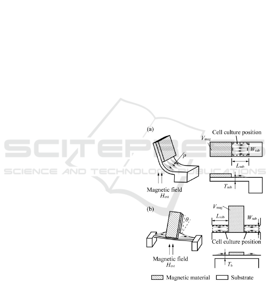
Figure 1: Schematic image of designed microstructure. (a)
Microstructure to apply bending deformation. (b)
Microstructure to apply torsion deformation.
bending and torsion stimulus to a cell, respectively,
when mechanical torque is applied to the substrate
and designed magneto-active microstructure. After
that, the microstructure was actuated under external
Nagase, H. and Iwase, E.
Design of Microstructure for Stimulating Mechanical Torque to Cells.
DOI: 10.5220/0007483802150219
In Proceedings of the 12th International Joint Conference on Biomedical Engineering Systems and Technologies (BIOSTEC 2019), pages 215-219
ISBN: 978-989-758-353-7
Copyright
c
2019 by SCITEPRESS – Science and Technology Publications, Lda. All rights reserved
215
magnetic field. We confirmed that the microstructure
can be actuated with sub-mm scale in radius of
curvature or angle of torsion.
2 DESIGN
Figure 1 shows the schematic image of the
microstructure which we designed and fabricated in
this study. When bending or torsion stimulus is
applied to a cell, it is necessary to consider the centre
position of torque where have no deformation. First,
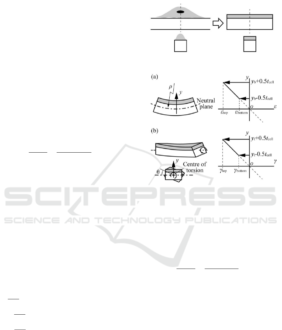
we discuss about bending stimulus. As shown in
Figure 2, we regard a cell on substrate as a rectangular
solid. When bending stimulus is applied to cell on
substrate with radius of curvature ρ, strain
distribution occurs to inside of the cell (Figure 3 (a)).
The strain ratio of top position of cell to bottom
position of cell is expressed as,
(1)
where ε
top
and ε
bottom
are the strain of top and bottom
position of the cell, y
b
is a distance from centre of
bending, i.e., neutral plane, to centre of the cell, and
t
cell
is the thickness of the cell. In the case of y
b
= 0,
namely, the position of neutral plane is centre of the
cell, we obtain ε
bottom
/ ε
top
= 1 from Equation (1). In
this case, ideal bending stimulus is applied to the cell.
On the other hand, in the case of y
b
>> t
cell
, i.e., the
position of neutral plane is too far from the cell, we
obtain ε
bottom
/ ε
top
≈ 1 from Equation (1). In this case,
we can estimate the stimulus of the cell as
compressive or tensile stimulus not bending stimulus.
By designing y
b
to near zero, we can apply more ideal
bending stimulus to cells. By calculating an equation
about the total stress on cross section of a cell and a
substrate, the value of y
b
is obtained. The equation is
expressed as,
(2)
where, E
cell
is the young’s elastic modulus. E
sub
and
t
sub
are the young’s elastic modulus and thickness of
cell culture substrate, respectively.
Next, we discuss about torsion stimulus. The
discussion is almost the same as the discussion about
bending stimulus. In case of rectangular cross-section,
strain distribution is non-linear. However, we
Figure 2: modelling of cultured cell on a substrate.
Figure 3: Schematic image of strain distribution in a cell.
(a) Strain distribution during bending stimulus. (b) Shear
strain distribution during torsion stimulus.
assumed linear strain distribution as a circular cross-
section to consider simply. When torsion stimulus is
applied to a cell on substrate with angle of torsion θ,
shear stress distribution occurs on inside of the cell
(Figure 3 (b)). The shear stress ratio of top position of
cell to bottom position of cell is expressed as,
(3)
where, γ
top
and γ
bottom
are the shear strain of top and
bottom position of the cell and y
t
is a distance from
centre of torsion to centre of cell. In the case of y
t
= 0,
namely, centre of torsion is centre of cell, we obtain
γ
bottom
/ γ
top
= 1 from Equation (3). In this case, ideal
torsion stimulus is applied to the cell. On the other
hand, in the case of y
t
>> t
cell
, we obtain γ
bottom
/ τ
top
≈
1 from Equation (3) and this equation indicates that
the torsion stimulus of cell is totally same as shear
stimulus. By designing y
t
to near zero, we can apply
more ideal torsion stimulus to the cell. By calculating
an equation about total shear stress on cross section
of a cell and a substrate, the value of y
t
is obtained.
The equation is expressed as,
BIODEVICES 2019 - 12th International Conference on Biomedical Electronics and Devices
216
(4)
where, G
cell
and G
sub
are shear modulus of the cell and
the cell culture substrate.
To apply bending or torsion stimulus to cells,
which cultured on sub-mm area, we utilized magnetic
anisotropy. By patterning a soft magnetic material on
beam, bending or torsion deformation can be obtained
as shown in Figure 1. The inclination of the magnetic
material is tuned by an external magnetic field
applied perpendicularly to the microstructure. By
calculating an equation about the magnetic torque and
the torque generated by elastic deformation of the
beam, magnitude of bending or torsion stimulus
against an external magnetic field is obtained. In the
case of rectangular beam, the equation is expressed as
(Iwase et al., 2005; Roark et al., 1989),
(5)
for bending stimulus and,
(6)
for torsion stimulus. Where, η is an angle of torsion
par unit length. V
mag
and M
s
are the volume and the
saturation magnetization of magnetic material,
respectively. L
sub
and W
sub
are length, and width of the
cell culture substrate.
3 FABRICATION AND
EXPERIMENTAL RESULT
We fabricated the microstructure. To decide detail
dimensions, we targeted C2C12 as an example. We
estimated the length of C2C12 on substrate about 100
μm. Therefore, the size of deforming substrate was set
100 μm in length and 50 μm in width. To fabricate the
microstructure with size of micro order, we utilized
silicon (Si) with sub-micron thickness as the substrate.
Si is suited to microfabrication and fabricate free
standing structure like Figure 1 easily. In the case of
C2C12, assuming that the thickness is 1μm, on 270-
nm Si substrate, y
b
= 635 nm and y
t
= 635 nm from
Equations (2) and (4). Therefore, we obtain ε
bottom
/ε
top
≈ 0.12 and τ
bottom
/τ
top
≈ 0.12, respectively.
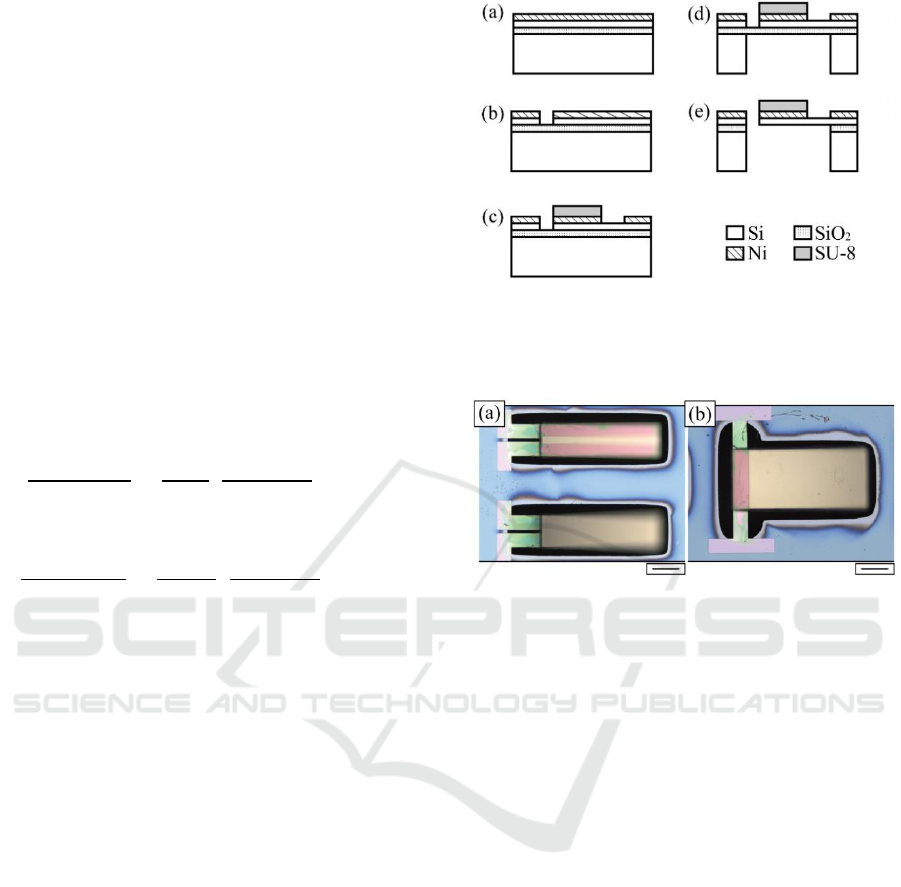
Fabrication process is shown in Figure 4. In the
fabrication process, silicon-on-insulator (SOI) wafer
was used. The thickness of the device Si layer, box
layer, and handle Si layer of the SOI wafer were 270
Figure 4: Cross-sectional diagrams of the fabrication
process. (a) Sputtering Ni layer. (b) Etching Ni and device-
Si layer. (c) Etching Ni layer and pattern SU-8 layer. (d)
Etching handle-Si layer. (e) Etching SiO
2
layer.
Figure 5: Images of fabricated microstructures. (a) The
microstructure to apply bending stimulus. (b) The
microstructure to apply torsion stimulus. Scar bars, (a) and
(b): 100 μm.
nm, 200 nm, and 300 μm, respectively. First, nickel
(Ni) layer with the thickness of 200 nm was sputtered
on the SOI wafer as a magnetic material (Figure 4 (a)).
Ni has a high saturation magnetization (M
s
= 0.6 T).
Then, the Ni layer was patterned using
photolithography, and the device Si layer was etched
with inductively-coupled-plasma reactive-ion etching
(ICP-RIE) using the Ni layer as a mask (Figure 4 (b)).
After that, the Ni layer was patterned again to remove
the Ni layer from the surface of cell culture region and
a negative photoresist (SU-8) was coated and
patterned on the Ni layer (Figure 4 (c)). We used SU-
8 to prevent a bending of beam, which is caused by a
strain mismatch between the Si layer and the Ni layer.
Then, the handle Si layer was patterned and etched
with ICP-RIE (Figure 4 (d)). Finally, the structure
was released by etching the box layer using HF
vapour (Figure 4 (e)). Fabricated microstructure is
shown in Figure 5. To compare with Equations (5)
and (6), we fabricated some microstructures with
different value of V
mag
by designing the width of Ni
layer.
We actuated the fabricated microstructures.
Figure 6 (a) shows the image of the experimental
Design of Microstructure for Stimulating Mechanical Torque to Cells
217
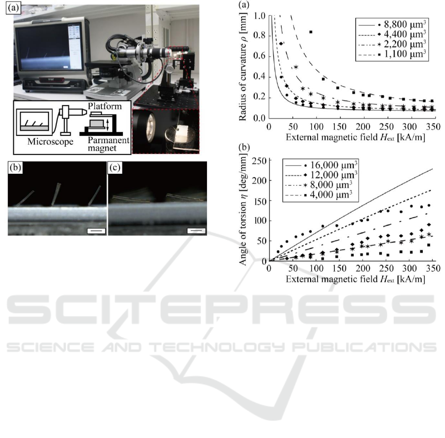
Figure 6: Images of experiment. (a) Experimental setup to
measure inclination angles of microstructures. (b)
Inclination of the microstructure for bending stimulus under
H
ext
= 343 kA/m. (c) Inclination of the microstructure for
torsion stimulus under H
ext
= 343 kA/m. Scar bars, (b) and
(c): 100 μm.
setup. Using a permanent magnet, external magnetic
field was perpendicularly applied to the
microstructure and the value of H
ext
was controlled by
setting the distance from the microstructure to the
permanent magnet. We observed and measured
inclination angle of magnetic material from the side
using microscope. Figures 6 (b) and (c) show the
microscope image of the microstructure applied
external magnetic field. We confirmed the actuation
of the microstructure. As shown in Figures 6 (b) and
(c), we can actuate some microstructures at the same
time. These results indicate that we can apply some
magnitudes of stimulus to cells in an external
magnetic field at the sometime.
We calculated the deformation of substrate, i.e., ρ
and η from the measured inclination angle. Figures 7
(a) and (b) show the relationship between H
ext
and ρ,
and the relationship between H
ext
and η, respectively.
Theoretical curves in Figures 7 (a) and (b) were
obtained from Equations (5) and (6), respectively.
Figure 7 (a) indicates that substrate totally deformed
in theory for each microstructures, which have
different value of V
mag
. The minimum ρ was less than
100 μm, which is almost same size as C2C12. This
result suggests that the microstructure might be
possible to apply enough magnitude of bending
stimulus to cells. On the other hand, from Figure 7 (b),
Figure 7: Experimental results. (a) Relationship between
external magnetic field and radius of curvature ρ. (b)
Relationship between external magnetic field and angle of
torsion η.
the actuation of the microstructure for torsion
stimulus was less than theoretical value for each
microstructures. Causes of this result might be effect
of thin rectangular-shaped cross section and/or effect
of the centre position of torque in the microstructure.
However, the maximum η was about 130 deg/mm.
From this result, the microstructure might be able to
apply torsion stimulus to the cell in some degree and
increasing the V
mag
or using other magnetic material,
which has higher saturation magnetization, larger η
might be able to apply to cell. By designing the
dimensions of the cell culture microstructure, we can
design the magnitude of bending or torsion stimulus.
4 CONCLUSIONS
We proposed the design of microstructures to apply
bending or torsion stimulus to cultured cell by using
magnetic anisotropy. As a result, we deformed
substrate with 100 μm in radius of curvature at the
least in the case of bending deformation and with 130
deg/mm angle of torsion at the most.
BIODEVICES 2019 - 12th International Conference on Biomedical Electronics and Devices
218

Firstly, we focused on the distance from centre of
mechanical torque to centre of cell on substrate and
we concluded that the distance is an important factor
when we design bending or torsion stimulus. We
fabricated the designed cell culture microstructure
using 270-nm-thick silicon and actuated under an
external magnetic field. We confirmed the actuation
of fabricated microstructure.
REFERENCES
Galbraith, C. G., Skalak, R., Chien, S., 1998. Shear stress
induces spatial reorganization of the endothelial cell
cytoskeleton, Cell motility and the cytoskeleton, 40,
317-330.
Hagiwara, M., Yabuta, N., Okuzaki, D., Inoue, T.,
Takashima, Y., Kimura, R., Ri, A., Ito, A., 2017.
Modest static pressure suppresses columnar epithelial
cell growth in association with cell shape and
cytoskeletal modification, Frontiers in physiology, 8,
00997.
Iwase, E., Shimoyama, I., 2005. Multistep sequential batch
assembly of three-dimensional ferromagnetic
microstructures with elastic hinges, Journal of
microelectromechanical systems, 14, 1265-1271.
Kozai, T., Eto, M., Yang, Z., Shimokawa, H., Lüscher, T.
F., 2005. Strain prevent pulsatile stretch-induced
proliferation of human saphenous vein smooth muscle
cells via inhibition of Rho/Rho-kinase pathway,
Cardiovascular research, 68, 475-482.
Roark, R., Young, W., Plunkett, R., 1989. Roark’s formulas
for stress and strain, Mcgraw-Hill. New York, 7
th
edition.
Wang, D., Zheng, W., Xie, Y., Gong, P., Zhao, F., Yuan,
B., Ma, W., Cui, Y., Liu, W., Sun, Y., Piel, M., Zhang,
W., Jiang, X., 2014. Tissue-specific mechanical and
geometrical control of cell viability and actin
cytoskeleton alignment, Scientific report, 4, 06160.
Wang, J. H.-C., Goldschmidt, P., Wille, J., Yin, F. C.-P.,
2001. Specificity of endothelial cell reorientation in
response to cyclic mechanical stretching, Journal of
biomechanics, 34, 1563-1572.
Design of Microstructure for Stimulating Mechanical Torque to Cells
219
