
A Data-driven Approach for Adding Facade Details to Textured LoD2
CityGML Models
Xingzi Zhang
1,∗
, Franziska Lippoldt
1,∗
, Kan Chen
2
, Henry Johan
1
and Marius Erdt
1,2
1
Nanyang Technological University, Fraunhofer IDM@NTU, Singapore
2
Fraunhofer Singapore, Singapore
Keywords:
Facade Details Addition, Data-driven, LoD2 CityGML Models.
Abstract:
LoD3 CityGML models (with facade elements, e.g., windows and doors) have many applications, however,
they are not easy to acquire, while LoD2 models (only roofs and walls) are currently largely available. In
this paper, we propose to generate LoD3 models by adding facade details to textured LoD2 models using a
data-driven approach. The existing reconstruction-based methods usually require high costs to obtain plausi-
ble LoD3 models. Instead, our proposed data-driven method is based on automatically detecting the facade
elements from the texture images and interactively selecting matched models from a 3D facade element model
database, then deforming and stitching them with the input LoD2 model to generate a LoD3 model. In this
manner, our method is free from reconstruction errors, such as non-symmetrical artifacts and noise, and it is
practically useful for its simplicity and effectiveness.
1 INTRODUCTION
CityGML models enable representing the semantics
of 3D cities at different levels of details (LoDs), so
that users can choose a suitable city representation
for their applications. An LoD3 CityGML build-
ing model not only inherits the simple exterior de-
tails of the building (i.e. walls and roofs) from its
LoD2 representation, but it also contains more de-
tailed exterior architectural structures (e.g., windows
and doors). LoD3 representation is useful in many
urban simulations (e.g., light pollution and shadow
simulation). However, different from other CityGML
representations with lower levels of details (LoD0,
LoD1 and LoD2), which are largely available, only a
limited number of LoD3 CityGML models are avail-
able. This is because the geometrical details on the
outer surfaces cannot be easily reconstructed with a
readily accessible pipeline.
Generally, there are three main approaches for
generating LoD3 models. The first is to create LoD3
models from 3D point clouds directly (Akmalia et al.,
2014; Hohmann et al., 2009). However, it usually
requires high costs and many manual efforts to ac-
quire, store and refine 3D point clouds in city scale.
The second is to convert existing models of other for-
∗
Joint first authors.
mats, such as Building Information Models (BIM), to
CityGML models (Geiger et al., 2015). However, the
BIM data of a city is not always available. The third is
to extend a model from LoD2 to LoD3 by adding 3D
facade details on the planar surfaces (e.g., walls) of a
building based on facade reconstruction using terres-
trial laser scanning (TLS) data or the images of the
buildings (Becker, 2011; Liu et al., 2017; Riemen-
schneider et al., 2012). However, this approach re-
quires high costs and may introduce many reconstruc-
tion errors. Segmentation-based methods, such as
(Riemenschneider et al., 2012), partition texture im-
ages into semantic image segmentations and then re-
construct the facade elements based on the segmenta-
tion results. By combining generic grammars and ob-
ject detectors, reconstruction errors can be avoided,
but these methods are constrained by the segmenta-
tion results, hence the quality of the texture images.
To the best of our knowledge, only a few works
have been done to extend LoD2 models to LoD3 mod-
els and they usually require complex computations
(Akmalia et al., 2014; Geiger et al., 2015; Becker,
2011; Liu et al., 2017). In this paper, a data-driven
pipeline for extending a textured LoD2 model to a
LoD3 model is proposed, where the facade elements
are automatically detected, interactively selected and
added to the textured LoD2 model input, based on
its texture images (Figure 1). The goal of the pro-
294
Zhang, X., Lippoldt, F., Chen, K., Johan, H. and Erdt, M.
A Data-driven Approach for Adding Facade Details to Textured LoD2 CityGML Models.
DOI: 10.5220/0007507802940301
In Proceedings of the 14th International Joint Conference on Computer Vision, Imaging and Computer Graphics Theory and Applications (VISIGRAPP 2019), pages 294-301
ISBN: 978-989-758-354-4
Copyright
c
2019 by SCITEPRESS – Science and Technology Publications, Lda. All rights reserved
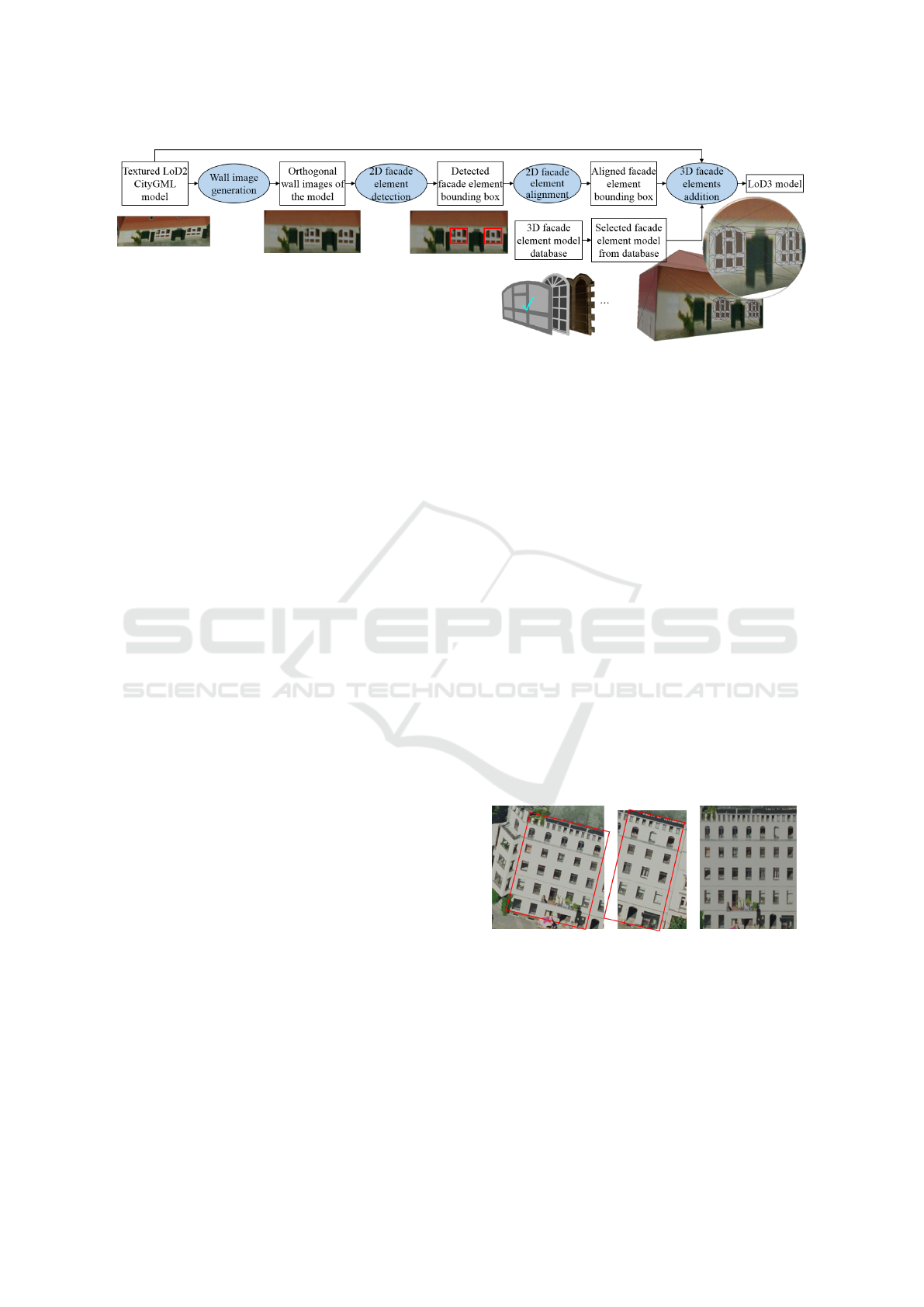
Figure 1: Our proposed pipeline illustrated using a window addition example.
posed pipeline is not accurate reconstruction of the
detailed facade structures, but to generate plausible
LoD3 models suitable for urban simulation (e.g., light
simulation and wind simulation). Our method has the
following contributions:
Contribution 1: facade element detection on low-
resolution texture images is a non-trivial task. We
propose a neural network approach that can automati-
cally detect 2D facade elements from texture images.
Contribution 2: it is not easy to directly recon-
struct the details of the facades. Many important prop-
erties such as symmetry might be lost due to recon-
struction errors. There are many similarities among
windows (doors), thus it is not necessary to recon-
struct the same window (door) multiple times. There-
fore, we propose to use a data-driven method by de-
tecting 2D facade elements from the texture images
and selecting matched 3D facade elements from a 3D
facade element database. This can ensure that our
generated model is free from reconstruction errors.
Contribution 3: the shapes of windows and doors
are usually simple and regular. Therefore, we propose
an effective facade element alignment and regulariza-
tion method as well as an effective mesh deformation
and stitching method to efficiently add windows and
doors to the textured LoD2 model input.
Our method provides a simple and practical way
of making full use of the available textured LoD2
models and adding facade details to the outer surfaces
of the models.
2 OUR PROPOSED PIPELINE
The input of our LoD2-to-LoD3 generation pipeline is
a textured LoD2 CityGML model. Our method gen-
erates polygon meshes of facade details, which can
be combined with the input model to form an out-
put LoD3 CityGML model. Figure 1 illustrates our
proposed pipeline with an example, in which 3D win-
dow structure is selected and added to enhance the
LoD2 building model input based on the window de-
tection result of its texture image. 3D door structure
can be handled similarly. In this paper, we mainly fo-
cus on adding windows and doors. Our pipeline has
four main steps:
1. Wall image generation: wall images of the
input textured LoD2 model are generated to
facilitate better 2D facade element detection.
2. 2D facade element detection: the 2D facade
elements are automatically detected from the
orthogonal wall images of the input model.
3. 2D facade element alignment: redundant de-
tection results are removed, and the detected
2D facade elements are processed to be well
aligned and have the same size.
4. 3D facade elements addition: the selected 3D
facade element models are deformed based
on the detected 2D facade elements and
stitched to the input model.
2.1 Wall Image Generation
(a) (b)
Figure 2: (a) An example in which a wall consists of two
raw texture images taken from non-frontal views. We com-
bine the areas enclosed by the red boxes together to form
one piece of wall texture image. (b) The generated wall tex-
ture image for this example.
In real-world cases, it is very difficult to acquire
high-quality wall textures for 3D building models in
city scale. The raw texture images of many LoD2
CityGML models, e.g., Berlin’s CityGML models
A Data-driven Approach for Adding Facade Details to Textured LoD2 CityGML Models
295
(Kolbe et al., 2005), are mostly broken and low-
resolution photos taken from top or side views with
overlapping and redundant parts. As such, the shapes
of the facade elements in the raw texture images are
distorted due to perspective distortion. Moreover,
one wall and its facade elements may be divided into
multiple raw texture images (Figure 2). These make
the 2D facade elements hard to be detected and pro-
cessed. Therefore, for each wall, one non-distorted
and non-fractured frontal-view texture image is re-
quired, before running our other procedures.
To achieve this, we render each wall of the input
textured LoD2 model into a texture image, using or-
thogonal projection. We make the virtual camera look
at the wall center with its up direction aligned with
the wall’s up direction. By setting the size of the or-
tho view to the size of the wall, we can render and
obtain orthogonal frontal view image of the wall. The
generated wall images are used as the input for the
subsequent steps.
2.2 2D Facade Element Detection
It is usually difficult to acquire high-quality wall tex-
tures for a city scale building dataset, for example in
Berlin CityGML dataset (Kolbe et al., 2005), even
after our preprocessing, the quality of the wall im-
ages are usually still low. In addition, in this dataset,
most of the texture images already show over expo-
sure or under exposure, i.e. the color range is mini-
mized and leads to noise when adjusting the images
with respect to the histogram. The inaccuracies in
the texture images originate mainly from a combina-
tion of hardware restrictions and photogrammetric er-
rors. Those are mainly the low image resolution, a
restricted color range and incorrect exposure settings.
Traditional object recognition methods (i.e. based on
edge detection) are difficult to deliver desired results.
Furthermore, deep learning techniques are currently
largely available and are able to produce better object
recognition results. As such, to tackle this 2D facade
element detection problem, we use the pixel-wise ob-
ject detection with Convolutional Neural Networks,
which is based on the Mask R-CNN (He et al., 2017).
We use the repository of (Abdulla, 2017) and make
several changes to improve the inference result for or-
thogonal wall images. The general structure is shown
in Figure 3.
We create a dataset of around 1,000 images for
training. Because orthogonal wall images have differ-
ent sizes and aspect ratios, we augment the orthogo-
nal wall images in our dataset to square images using
cropping or padding. We pad every orthogonal wall
image and include it in the dataset. If the orthogonal
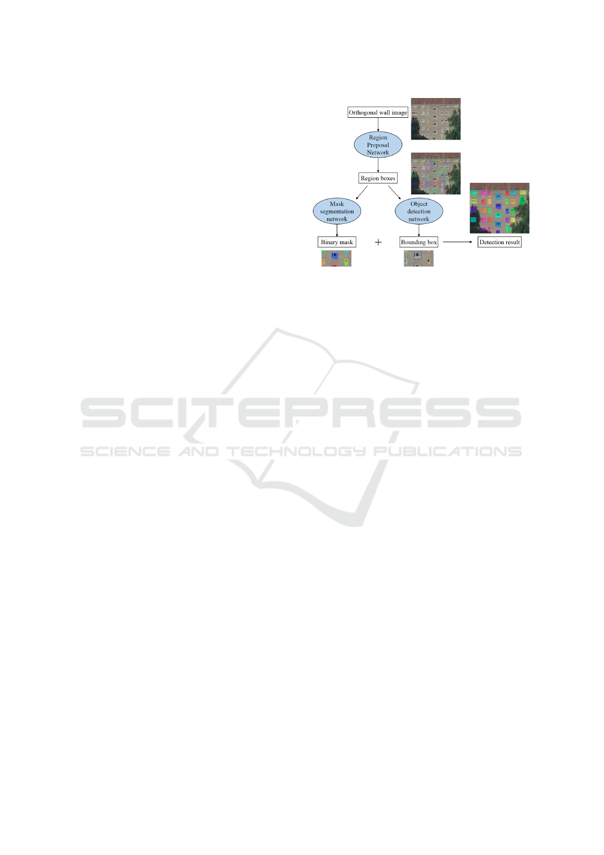
Figure 3: A neural network approach for detecting 2D fa-
cade elements.
wall image size is larger than our training image size,
we apply cropping.
We use the ResNet backbone and apply transfer
learning to adapt the network for facade element de-
tection: we change the structure such that detection
and classification is only made for facade elements,
e.g., windows and doors. The first part of the network
uses the Region Proposal Network (RPN) to enable
fast region proposal. The RPN allows faster detection
of possible facade element regions proposed for the
next step. In the following steps, given the input im-
age and region proposal, we determine the bounding
boxes and masks for the facade elements. The de-
tection of bounding boxes is independent of the mask
segmentation. The bounding boxes are rectangles and
cover the detected facade element. The masks rep-
resent the shape information of the detected facade
element. As a resulting output, we have a binary im-
age with the masked regions as well as bounding box
coordinates. The overall loss function L is defined as
follows:
L = L
RPN
+ L
MRCNN
(1)
L
RPN
= L
class−RPN
+ L
BB−RPN
(2)
L
MRCNN
= L
class−MRCNN
+ L
BB−MRCNN
+ L
mask
(3)
The Region Proposal Network’s loss function con-
tains the log loss L
class−RPN
for classes and the
Smooth L1 loss L
BB−RPN
for the bounding boxes.
The Mask R-CNN loss function is the sum of the
log loss L
class−MRCNN
for the classes, the Smooth L1
loss L
BB−MRCNN
for the bounding boxes and the pixel-
wise binary cross entropy loss L
mask
for the mask pre-
diction. While the Region Proposal Network acts on
the whole image, the Mask R-CNN only has the rec-
ommended regions as an input and therefore acts on
subregions. Note that mask and bounding box gener-
ation are independent of each other. They do not rely
GRAPP 2019 - 14th International Conference on Computer Graphics Theory and Applications
296
on each other, but have the same input as received
from the region proposal.
We minimize the overall loss function in order to
detect the facade elements. Thanks to our subdivided
structure, we can do so by minimizing each loss part
separately. The classification loss minimization can
help us to classify our desired category which is the
facade element. RPN loss is crucial to minimize to
get a more optimal region proposal indicating the po-
tential facade element area. This region proposal is
not based on color value gradients, which may lead to
many more non-relevant features, instead, it focuses
on capturing actual window complex. By minimizing
the bounding box and mask loss, we can detect the lo-
cation and shape of a facade element. We also use the
mask to check and verify the results of the bounding
box in terms of double detection. In some cases, one
facade element is detected and split into two bounding
boxes that are either touching each other or overlaying
one another.
In contrast to common object detection networks,
we do not use the average precision score as a crite-
ria for improving the network, but the total number of
correctly detected windows: we especially focus on
improving the recall value for the bounding boxes. In
other words, we prefer finding the exact amount of fa-
cade elements without detecting too many or too few
facade elements to optimising the mask for pixel-wise
correctness.We also adapt the detection threshold op-
timally such that most of the facade elements are de-
tected and the error of false detection is minimized.
2.3 2D Facade Element Alignment
There are two forms of output for our 2D facade el-
ement detection step: 2D mask and bounding box of
the facade elements. We use the mask results to check
and verify the bounding box results. The detected 2D
mask is also intended for generating detailed facade
element contours, however, currently the detected 2D
mask is too noisy due to the low quality of the ac-
quired raw textures. Therefore, we choose to use the
detected 2D bounding boxes to represent the facade
element contours. In the future, we plan to improve
our detection method to obtain detailed facade ele-
ment contours.
As shown on the left side of Figure 4, most of the
times, the detected facade element bounding boxes on
one wall image are not of the same size, and they are
also not well aligned. However, in reality, the win-
dows on one wall normally (1) have the same size and
(2) are well aligned in horizontal and vertical direc-
tions. To prepare a better input for the next step of
adding 3D facade elements as well as for generating
a natural-looking wall, we first delete the overlapping
bounding boxes and then regularize the detection re-
sults based on these two heuristics.
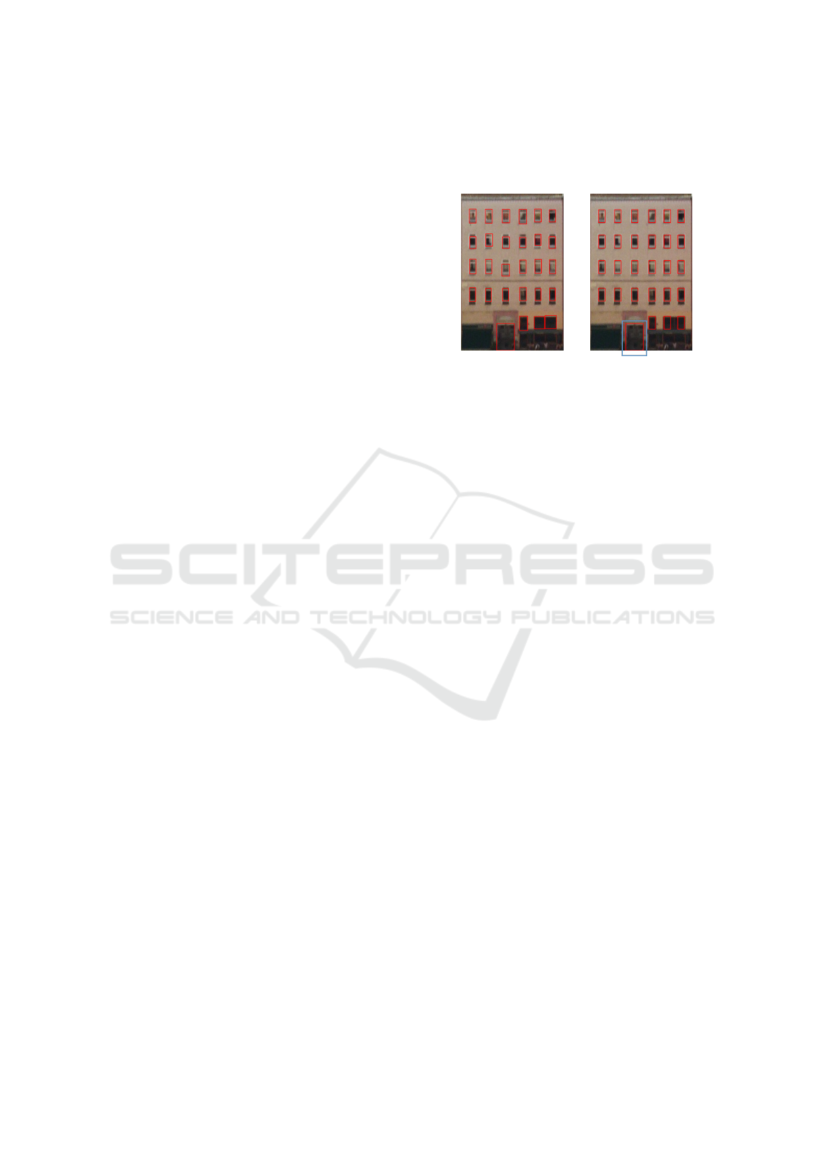
Figure 4: The sub-figures on the left and right show an ex-
ample of the original facade element detection result and
the result after adjustment, respectively. In this example,
N
cluster
= 3.
(1) To ensure that the detected facade elements
have the same size of bounding boxes, we first com-
pute the average width and height, avg
w
and avg
h
, for
all the detected facade element bounding boxes. Then
for each single facade element bounding box, we sub-
tract avg
w
and avg
h
from its width and height. Here
we set a threshold for width and height difference,
dif
w
and dif
h
(dif
w
, dif
h
> 0), based on the dimensions
of the wall image. If the absolute difference between
a facade element bounding box’s width (height) and
avg
w
(avg
h
) exceeds the specified threshold, we con-
sider this element as an outlier and exclude it from
the computation of avg
w
and avg
h
in the next itera-
tion. We repeat this procedure until no new outlier is
found, and then the finally obtained avg
w
and avg
h
are
considered as the target regularized width and height
for the facade elements. For the example in Figure 4,
we set the threshold to 4% of the width and height of
the wall image, and it took two iterations for the loop
to converge. Generally, the loop converges within ten
iterations when the threshold is set to be between 2%
and 5%, since most of the detected bounding boxes
are allocated regularly.
(2) To fulfill the second heuristic, we first compute
the center for each facade element bounding box, c
ix
and c
iy
(i = 1,2,. . . , N) in horizontal and vertical di-
rections. Based on these values, we adjust the facade
elements in horizontal and vertical directions. Here
we take the x direction adjustment as an example to
illustrate our method. We first sort the facade ele-
ments based on their c
ix
values in ascending order.
After that, we apply a rule-based clustering algorithm
to segment them. Then, we adjust the center positions
of all the facade elements in one cluster to the same x
value (c
x
).
The rule-based clustering is as follows: for the
A Data-driven Approach for Adding Facade Details to Textured LoD2 CityGML Models
297
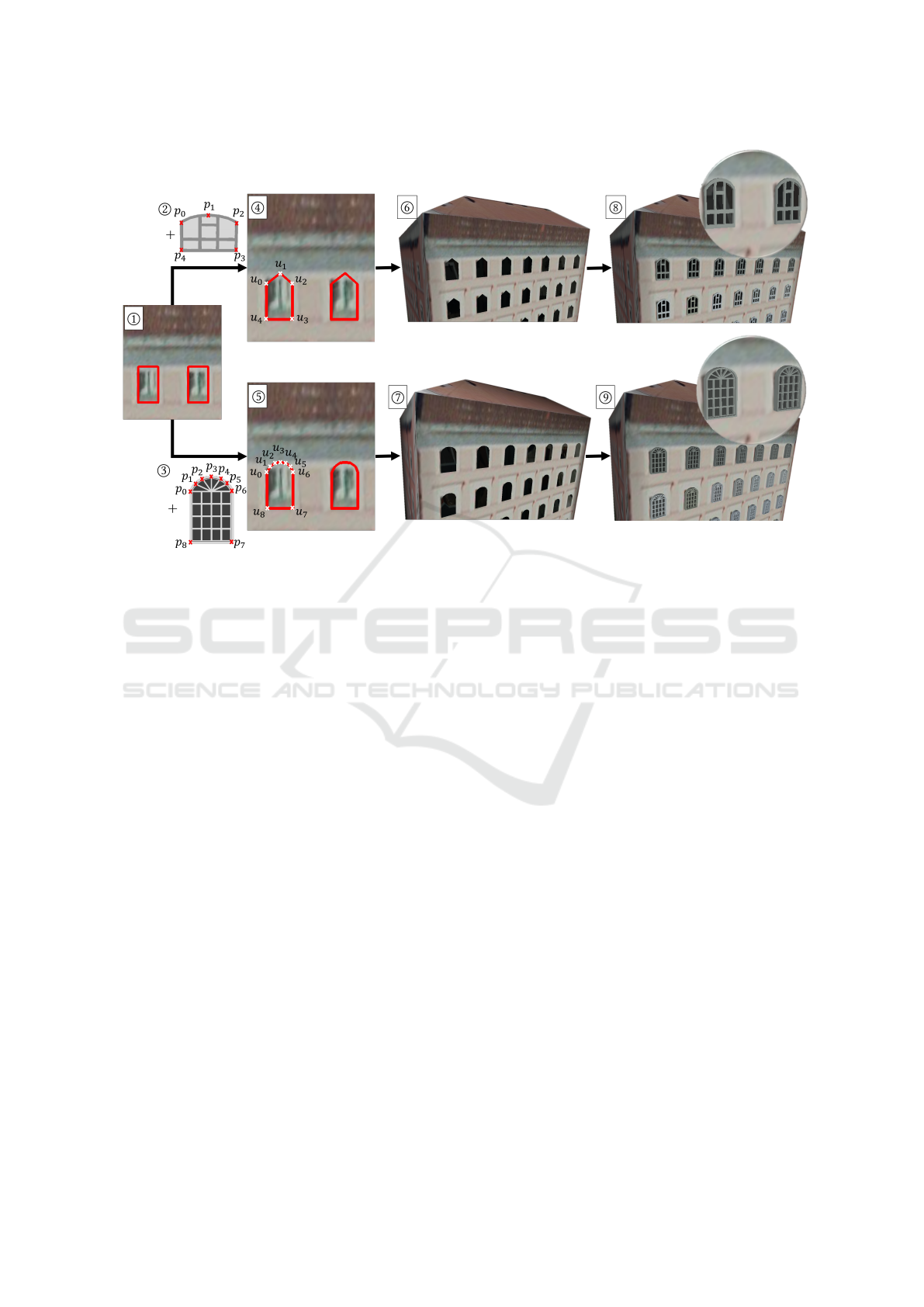
Figure 5: When choosing a 3D facade element model from the database, we also obtain the 3D feature points which define
the boundary of this model. Suppose that the window detection output is
1
. If we choose
2
as the matched window model,
then we will have the corresponding feature point result in
4
. By cutting holes following the computed feature points, we
obtain
6
, and
8
is the enhancement result with window
2
. Likewise, if we choose
3
, then
9
is the enhancement result.
sorted version of c
ix
(i = 1, 2, . . . ,N), we compute
the difference
|
d
ix
|
between the adjacent elements (for
i = 2, . . . , N, d
ix
= c
ix
−c
i−1x
, and for i = 1, d
ix
= 0). If
one facade element has a
|
d
ix
|
greater than dif
w
, we ap-
ply a segmentation and consider this facade element
as the start point for a new cluster. Then for each clus-
ter, we find the rounded average of the c
ix
values and
use it as the center x value (c
x
) for the facade elements
in this cluster.
We also apply the same method to c
iy
in y direc-
tion. In this manner, we adjust and align the center
positions for all the facade elements. Note that we
allow users to define a threshold N
cluster
for the clus-
ter size. For those clusters whose sizes are smaller
than N
cluster
, their facade elements are marked as ir-
regular shapes, and the computed regularized width
and height would not be applied to them. The right
side of Figure 4 shows such an example in which the
irregular facade element is enclosed in a blue box.
Besides adjusting the detection results, we also
provide the users a heuristic approach to identify
doors in this step, so that a different 3D facade ele-
ment model can be selected for the doors in the next
3D facade elements addition step. Our door identifi-
cation is based on the common sense that the doors are
usually the nearest to the ground among all kinds of
facade elements. Therefore, if the distance from the
lower line of the bounding box of a facade element to
the ground is approximately zero, we identify this fa-
cade element as a door. For the example in Figure 4,
the facade element enclosed in blue box is identified
as a door.
2.4 3D Facade Elements Addition
Based on the detected facade elements, we interac-
tively select matched 3D facade element models from
a 3D facade element database. In this database, the
model definitions include the basic geometry infor-
mation of the models and also the feature points for
defining the 3D boundary of the models. We resize
and align the selected 3D models according to the de-
tected 2D bounding boxes, to ensure that they have
the same locations, orientations and sizes. This com-
putation is done in the following way: we first trans-
form the 3D facade element models to align them to
the target wall. This step guarantees that the mod-
els face the same direction as the wall, i.e. have the
same normal. Then we position the 3D models to the
centers of the detected 2D bounding boxes, and resize
them to match their bounding boxes with the detected
bounding boxes. By doing these three steps, i.e. trans-
formation, position and resizing, these 3D facade el-
ement models are located in the desired places on the
GRAPP 2019 - 14th International Conference on Computer Graphics Theory and Applications
298
target wall as the detected 2D bounding boxes.
After that, based on the feature points on the
boundary of the selected 3D facade elements ~p
i
(i =
1,2,. . . , M) (provided in the model definitions), we
compute the corresponding feature points ~u
i
(i =
1,2,. . . , M) on the detected 2D bounding boxes (we
lift these points to 3D using the walls depth value).
We also cut holes in the walls of the input LoD2
model following the boundary defined by~u
i
. This step
is illustrated in Figure 5.
We then deform the selected 3D facade elements
to align with the detected 2D facade element bound-
ing boxes in a way that the pairs of feature points coin-
cide with each other. To achieve this deformation, we
adopt the radial basis function interpolation method.
We build three linear equation systems using the M
pairs of feature points (~p
i
and ~u
i
) to compute the x, y
and z coordinates of the deformed position ~u, respec-
tively. We take the computation for the x coordinate
of ~u as an example:
u
ix
=
M
∑
j=1
a
j
g(k~p
i
−~p
j
k) + c
0
+ c
1
p
ix
+ c
2
p
iy
+ c
3
p
iz
, (4)
M
∑
j=1
a
j
= 0,
M
∑
j=1
a
j
p
jx
= 0,
M
∑
j=1
a
j
p
jy
= 0,
M
∑
j=1
a
j
p
jz
= 0 (5)
Here g (.) denotes a radial basis function, and in
our implementation, we use g(x) =
p
log(1 + x
2
).
The weights a
i
and the coefficients c
0
, c
1
, c
2
, c
3
can
be obtained by solving this equation system (Equa-
tions (2) and (3)), then they are substituted back to
Equation (2) to form the deformation function: u
x
=
∑
M
j=1
a
j
g(k~p −~p
j
k) + c
0
+ c
1
p
x
+ c
2
p
y
+ c
3
p
z
. This
function takes ~p as input and computes the x coordi-
nate of its deformed position ~u. Likewise, we com-
pute the y and z coordinates of ~u. By doing so, we
deform the 3D facade elements to align with the the
detected 2D facade element bounding boxes on the
wall images. After this, we stitch them back with the
LoD2 model to generate a LoD3 model by merging
the overlapped feature point pairs.
We also propose a method to fix the colors of the
3D facade elements, i.e. to adjust the colors of the
3D facade elements based on the original colors of
the 2D target facade elements in the wall image. We
cluster the colors from the 2D target facade element
into two, using K-means clustering. The cluster size
is set to two, because most of the facade elements that
we are currently dealing with are windows, and they
normally have different colors for frames and glass
panes. Based on this, we select the dominant color
in each cluster and assign it to the frame part or the
rest part of the 3D model (differentiated based on the
material definition), respectively.
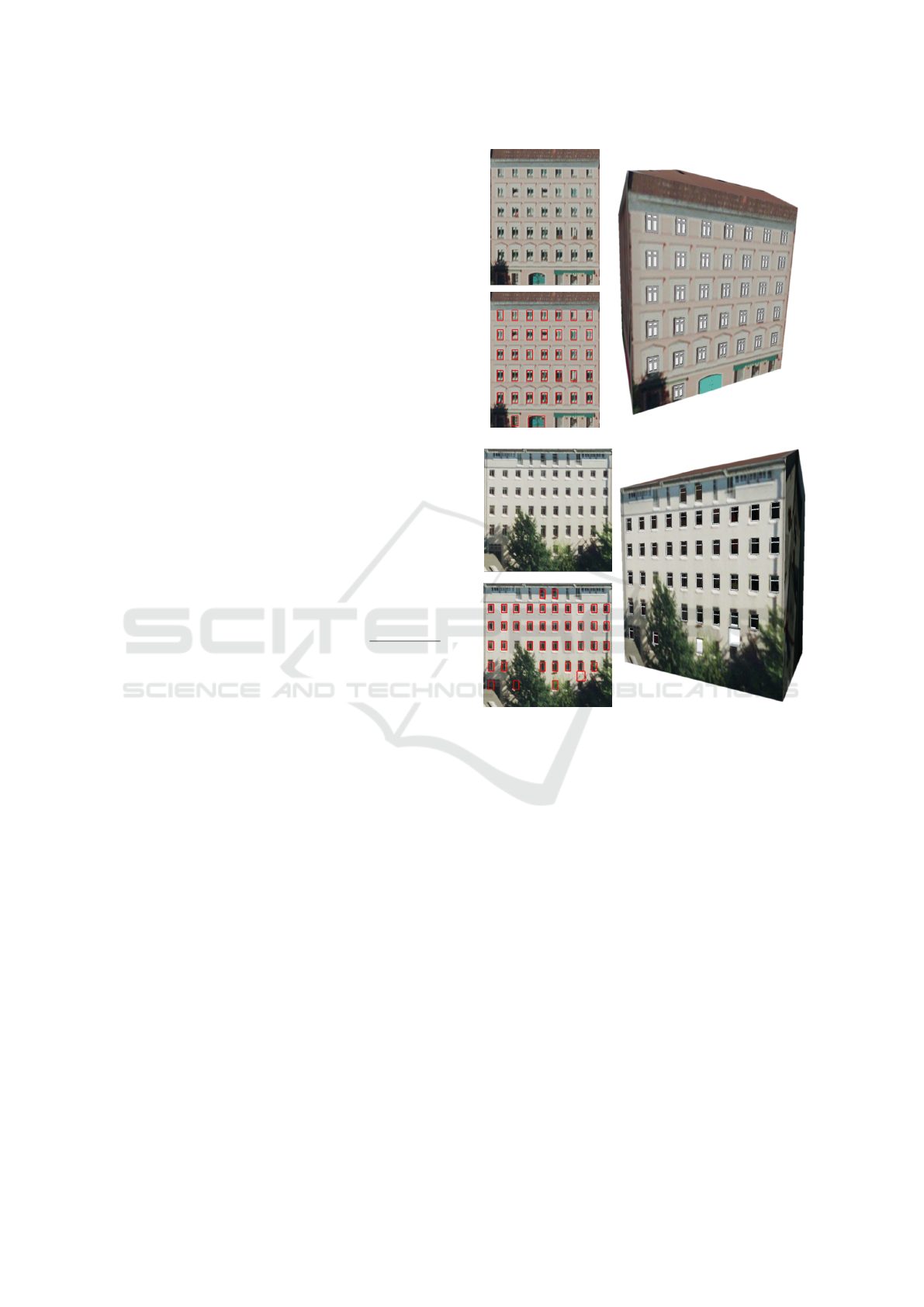
(a)
(b)
Figure 6: Examples of the generated orthogonal wall tex-
tures (top left), the detected and aligned 2D bounding boxes
for the facade elements (bottom left) and the LoD3 building
output (right).
3 RESULTS
As shown in Figures 1, 5, 6, and 9, our method can ef-
fectively add details to textured LoD2 building mod-
els. All the models and texture images used in the
examples are from Berlin’s CityGML model (Busi-
ness Location Center, 2018). In Figure 6, the input
wall textures, the detected and aligned 2D facade el-
ement bounding boxes and the enhancement results
are shown side by side for comparison. Based on the
detected 2D facade elements, our alignment and addi-
tion methods can generate a visually plausible LoD3
building model. A snapshot of a virtual street scene
in LoD3 is presented in Figure 9 to demonstrate our
enhancement results on a street level.
Since the raw texture images of many LoD2
A Data-driven Approach for Adding Facade Details to Textured LoD2 CityGML Models
299
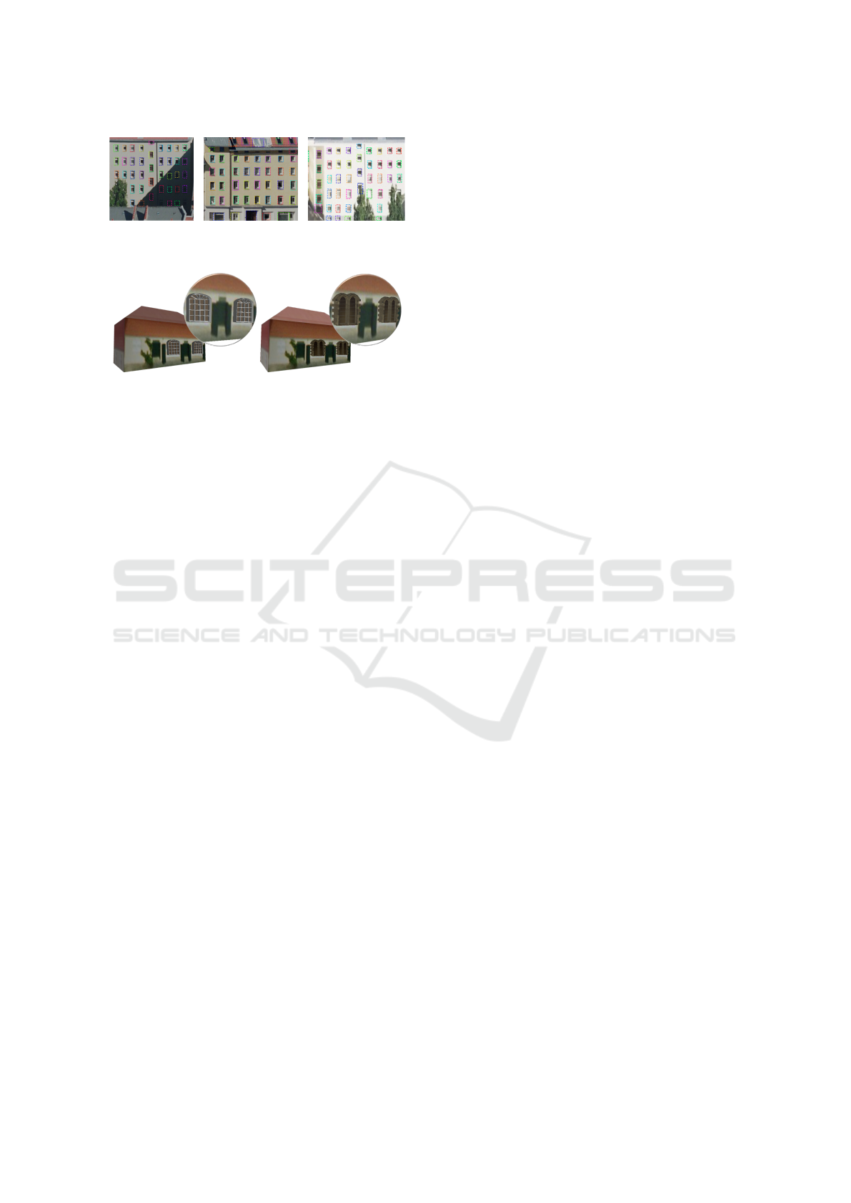
(a) (b) (c)
Figure 7: Examples of facade element detection results.
Figure 8: Decorate a LoD2 model with different windows.
CityGML models are of low resolution, it is hard to
retrieve all the geometric information of the facade
elements from one single texture image. In Figures
2, 6 and 7, we can see that the wall textures were
taken under different illumination and view angles.
Despite that we can generate orthogonal front view
wall images as the input for the enhancement, the im-
ages of the facade elements still suffer from distor-
tion, low resolution and shading problems. In this
case, the reconstruction-based methods are not suit-
able. By contrast, the proposed pipeline avoids these
problems by generating regularized contours based on
detecting bounding boxes, applying simple geometry
rules, and incorporating information from our 3D fa-
cade element database.
Figure 7 shows a typical output for our 2D facade
element detection step. We computed the recall and
precision in terms of the detected windows: positive
(negative) means that this object is classified as (not)
a window. True positives are the correctly detected
windows while false positives are the incorrectly de-
tected ones. The high recall rate means that we only
have very few false positive cases in our detection,
which guarantees proper input for the alignment and
addition procedures. For the 36 wall texture images
that we have tested on, we can achieve a recall of 94%
and a precision of 83%.
For 2D facade element detection, the training and
detection is on a PC with 8 GB GPU. With an average
of 34.3 windows per facade image, our average eval-
uation time is 2.25s per image. While the fastest pre-
diction is made in 1.6s, the slowest inference is made
in 4.6s. For a generated wall image, its facade element
detection result is saved in a JSON file. For all the en-
hanced building examples in this paper, the alignment
and detail addition procedures were implemented on
another PC with 8-core CPU working at 2.60GHz.
With a wall image and the corresponding JSON file as
input, the average alignment and detail addition time
for a building model was around 1s, which excluded
the interactive 3D facade model selection time and the
alignment threshold set time. This average time was
computed based on the examples presented in this pa-
per.
Besides constructing a LoD3 model based on the
wall textures, the proposed pipeline also can be ap-
plied to decorate a textured LoD2 model using user
desired 3D facade element models (Figure 8). In ad-
dition, we can decorate a user specified 3D facade el-
ement to any location as user desired.
4 CONCLUSIONS AND FUTURE
WORK
In this paper, we have proposed a data-driven
approach for adding facade details to a textured
LoD2 CityGML model. Different from the existing
reconstruction-based LoD3 model generation meth-
ods, our approach tackles this problem by detect-
ing, interactive selecting, deforming and stitching 3D
facade element models to obtain a plausible LoD3
model for the input LoD2 model. Some results are
provided to show how the proposed pipeline works.
For now, the 3D model selection is done manu-
ally. We plan to tackle this problem in a more efficient
and deformation-friendly manner, considering that fa-
cade elements, such as windows and doors, usually
have symmetrical and regular geometries. In this way,
the correspondence between the detected 2D contour
and the boundary of the retrieved 3D facade element
model can be easily established for the deformation.
In addition, despite that in the 2D facade element
alignment step, clustering is applied to classify the de-
tected windows into different groups, currently we do
not consider this information when selecting the 3D
models for the windows, i.e. we use the same win-
dow model for all the windows. We will include this
information in the automatic 3D model selection plan
to improve the plausibility of the output LoD3 model.
The style of the buildings would also be considered
for more aesthetically pleasing results.
Because of the complex u-v coordinates of the
original CityGML model, the rendered facade images
still contain some parts of the rooftop, neighboring
houses partially, and a variety of trees. As such, the
detection algorithm sometimes fails to detect or gives
wrong detection results when there exists occlusions.
We plan to incorporate the detection of those addi-
tional objects in the future, to clean up the facade im-
ages and guarantee a better quality of the results.
Currently our database only contains 3D window
GRAPP 2019 - 14th International Conference on Computer Graphics Theory and Applications
300

Figure 9: A virtual street scene in LoD3 built by enhancing LoD2 models using our proposed pipeline.
and door models. In the future, more facade element
models, such as balconies and chimneys, will be in-
cluded. We are also working on making this process
more intelligent and comprehensive by incorporating
more advanced shape classification and deformation
procedures into our pipeline.
ACKNOWLEDGEMENTS
This research is supported by the National Re-
search Foundation, Prime Ministers Office,
Singapore under the Virtual Singapore Pro-
gramme. Berlin’s CityGML model source
can be downloaded from the following link:
https://www.businesslocationcenter.de/en/downloadportal.
REFERENCES
Abdulla, W. (2017). Mask R-CNN for object detection
and instance segmentation on Keras and TensorFlow.
https://github.com/matterport/Mask RCNN.
Akmalia, R., Setan, H., Majid, Z., Suwardhi, D., and
Chong, A. (2014). TLS for generating multi-LOD of
3D building model. In IOP conference series: Earth
and environmental science, volume 18, pages 12–64.
IOP Publishing.
Becker, S. (2011). Towards Complete LOD3 Models–
Automatic Interpretation of Building Structures. In
Photogrammetric Week, pages 39–56.
Business Location Center (2018). Berlin 3D - Download
Portal provided by the Business Location Center. [On-
line; accessed 7-November-2018].
Geiger, A., Benner, J., and Haefele, K. H. (2015). General-
ization of 3D IFC building models. In 3D Geoinfor-
mation Science, pages 19–35.
He, K., Gkioxari, G., Doll
´
ar, P., and Girshick, R. (2017).
Mask R-CNN. In Computer Vision (ICCV), 2017
IEEE International Conference on, pages 2980–2988.
IEEE.
Hohmann, B., Krispel, U., Havemann, S., and Fellner, D.
(2009). Cityfit-high-quality urban reconstructions by
fitting shape grammars to images and derived textured
point clouds. In Proceedings of the 3rd ISPRS Inter-
national Workshop 3D-ARCH, volume 2009, page 3D.
Kolbe, T. H., Gr
¨
oger, G., and Pl
¨
umer, L. (2005). CityGML:
Interoperable access to 3D city models. In Geo-
information for Disaster Management, pages 883–
899. Springer.
Liu, H., Zhang, J., Zhu, J., and Hoi, S. C. H. (2017). Deep-
Facade: A Deep Learning Approach to Facade Pars-
ing. In Proceedings of the Twenty-Sixth International
Joint Conference on Artificial Intelligence, IJCAI 17,
pages 2301–2307.
Riemenschneider, H., Krispel, U., Thaller, W., Donoser, M.,
Havemann, S., Fellner, D., and Bischof, H. (2012).
Irregular lattices for complex shape grammar facade
parsing. In Computer Vision and Pattern Recogni-
tion (CVPR), 2012 IEEE Conference on, pages 1640–
1647. IEEE.
A Data-driven Approach for Adding Facade Details to Textured LoD2 CityGML Models
301
