
A Tool for High-level Modeling of Analog/Mixed Signal Embedded
Systems
Daniela Genius
1
, Rodrigo Cortés Porto
1,3
, Ludovic Apvrille
2
and François Pêcheux
1
1
Sorbonne Université, LIP6, CNRS UMR 7606, Paris, France
2
LTCI, Télécom ParisTech, Université Paris-Saclay, Paris, France
3
Technische Universität Kaiserslautern, Kaiserslautern, Germany
Keywords:
Embedded Systems, Analog/Mixed Signal Design, Virtual Prototyping, Code Generation.
Abstract:
Embedded systems are commonly built upon heterogeneous digital and analog integrated circuits, including
sensors and actuators. Model-driven approaches for designing software and hardware have been proposed, yet
they are generally limited to the digital parts of systems. This paper presents the extension of an integrated
modeling and simulation tool for the verification and virtual prototyping of embedded systems described at
different abstraction levels to analog/mixed-signal systems.
1 INTRODUCTION
Model-driven techniques make use of high level
models to create the specification of the software,
and then rely on model transformations to gener-
ate the corresponding source code. They have been
widely proposed for designing software and hard-
ware. Nonetheless, in most cases, these approaches
are limited to the digital part of the system, whereas
embedded systems — e.g. robotics and automo-
tive systems — are frequently built upon heteroge-
neous hardware e.g. processors, FPGAs, DSPs, hard-
ware accelerators, digital and analog analog/mixed
signal(AMS) and radio frequency(RF) circuits.
In very early design phases, rapid but less precise
exploration of the design space is required. For this
purpose, heterogeneous embedded systems require a
high-level representation that includes models of their
AMS and RF components. The problems of synchro-
nization between the time domains of the different
Models of Computation (MoC) however must be pre-
cisely considered.
This paper presents the integration of models for
analog components into an existing multi-level mod-
eling and virtual prototyping tool. In the modeling
phase, we define a way to capture both digital and
analog domains. In the prototyping phase, we propose
a way to combine a Timed Data Flow (TDF) simula-
tion with an event-based (SystemC) simulation.
Related work in the next section demonstrates the
lack of an integrated approach offering at the same
time high-level heterogeneous system modeling, for-
mal verification, correct-by-construction code gener-
ation, and cycle/bit precise simulation of both the dig-
ital and the analog parts. Section 3 presents the bases
of this work, Section 4 our contribution and Section 5
provides results for a larger case study.
2 RELATED WORK
Well established tools in analog/mixed signal design,
like Ptolemy II (Ptolemy.org, 2014), based upon a
data-flow model, address heterogeneous systems by
defining several sub domains using hierarchical mod-
els. Instantiation of elements controlling the time syn-
chronization between domains is left to the responsi-
bility of designers.
Metropolis (Balarin et al., 2003) is based on a high
level model and facilitates the separation of computa-
tion from communication concerns. Heterogeneous
systems are taken into consideration, but heterogene-
ity can only be represented using processes, mediums,
quantities and constraints. Hierarchical models are
not allowed: all processes should be implemented in
the same hierarchical level. Metro II (Davare et al.,
2007) introduces hierarchy and allows Adaptors for
data synchronization as a bridge between the seman-
tics of components belonging to different MoCs. The
model designer still has to implement time synchro-
nization. As a common simulation kernel handles all
process execution, MoCs are not well separated.
SystemC (IEEE, 2011) is a C++ class library
which makes it possible to model (digital) hardware
Genius, D., Porto, R., Apvrille, L. and Pêcheux, F.
A Tool for High-level Modeling of Analog/Mixed Signal Embedded Systems.
DOI: 10.5220/0007520804330440
In Proceedings of the 7th International Conference on Model-Driven Engineering and Software Development (MODELSWARD 2019), pages 433-440
ISBN: 978-989-758-358-2
Copyright
c
2019 by SCITEPRESS – Science and Technology Publications, Lda. All rights reserved
433
on multiple levels of abstraction. Among the frame-
works based on SystemC are HetSC (Herrera and Vil-
lar, 2007), HetMoC (Zhu et al., 2010) and ForSyDe
(Niaki et al., 2012), all having the disadvantage that
instantiation of elements and controlling the synchro-
nization have to be managed by the designer.
SystemC-AMS extensions (Accellera Systems
Initiative, 2010) is a standard describing an exten-
sion of SystemC with AMS and RF features (Vachoux
et al., 2003). The usual approach for modeling the
digital part of a heterogeneous system with SystemC
is to rely on the Discrete Event (DE) part of SystemC
AMS extensions. The Timed data Flow (TDF) part
adds support for signals where data values are sam-
pled with a constant time step.
In the scope of the project BeyondDreams (Be-
yond Dreams Consortium, 2011), a mixed analog-
digital systems proof-of-concept simulator has been
developed, based on the SystemC AMS extension
standard. Another simulator is proposed in the
H-Inception project(H-Inception Consortium, 2015).
All of these approaches rely on SystemC AMS code
i.e. they don’t provide a high-level interface for spec-
ifying the application.
Outside the analog/mixed signal domain,
UML/SysML based modeling techniques such as
MARTE and Gaspard2 (Vidal et al., 2009; Selic
and Gérard, 2013; Gamatié et al., 2011) are popular
for capturing embedded systems, but are scarcely
used for heterogeneous system design with virtual
prototyping in mind. Furthermore, with very few
exceptions such as (Taha et al., 2010; Li et al., 2018),
they do not support refinement until a low level of
abstraction i.e. cycle bit accurate level nor provide
full-system simulation.
The B method and more recently Event-B (Abrial,
2010) model systems at different abstraction levels
and makes it possible to mathematically prove con-
sistency between refinement levels. Based on set the-
ory and the B language, the B method is well es-
tablished in large-scale public/private projects (urban
transports etc.) but less widespread in industry than
UML/SySML based approaches.
Very few works exist which bridge the gap be-
tween digital and analog aspects. One of these contri-
butions stems from the Micro-electromechanical sys-
tems (MEMS) community (Bouquet et al., 2012).
It transforms structural SysML diagrams to VHDL-
AMS code. Another is Discrete Event System Spec-
ification (DEVS (Concepcion and Zeigler, 1988)), a
modular and hierarchical formalism for modeling and
analyzing general systems that can be discrete event
or continuous state systems; the latter can be de-
scribed by differential equations, or hybrid systems.
A B Y
R= 1
D= 1
Tm= 6 ms Tm= 4 ms
Tp= 4 ms
R= 3
Tp= 2 ms
D= 0
R= 2
D= 0
Tp= 2 ms
TDF Cluster
Figure 1: TDF Cluster.
3 PRELIMINARIES
Timed Data Flow. SystemC AMS uses among oth-
ers the Timed Data Flow (TDF) Model of Compu-
tation which is based on the timeless Synchronous
Data Flow (SDF) semantics (Lee and Messerschmitt,
1987b). A TDF module is described with an attribute
representing the time step and a processing function.
The processing function corresponds to a mathemat-
ical function which depends on the module inputs
and/or internal states. At each time step, a TDF mod-
ule first reads a fixed number of samples from each
of its input ports, then executes the processing func-
tion, and finally writes a fixed number of samples to
each of its output ports. TDF modules can interact
with the DE world, such as digital Multi-Processor
System-on-Chip (MPSoC) platforms, using converter
ports.
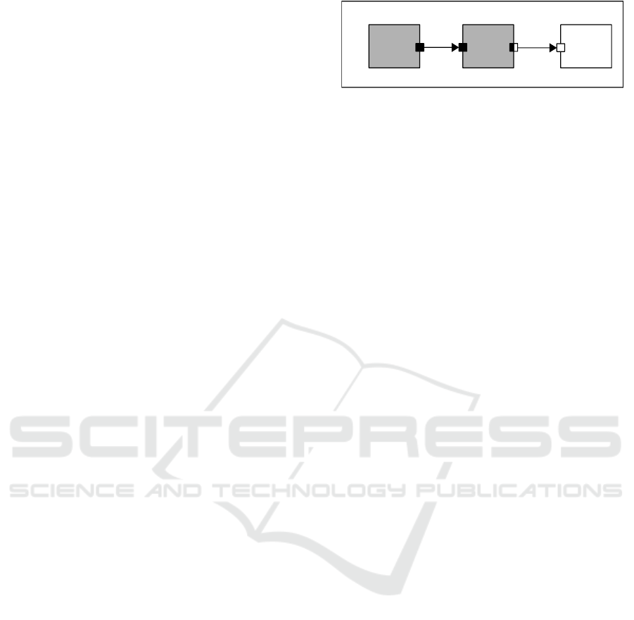
Figure 1 shows a TDF cluster. DE modules
are represented as white blocks, TDF modules as
gray blocks, TDF ports as black squares, TDF con-
verter ports as black and white squares, DE ports as
white squares and TDF signals as arrows. So-called
converter ports, shown as black-and white squares,
serve as interface between the TDF and DE MoC. The
TDF modules have the following attributes:
• Module Timestep (Tm) denotes the period during
which the module will be activated. One module
will only be activated if there are enough samples
available at its input ports.
• Rate (R). Each module will read or write a fixed
number of data samples each time it is activated.
This number is annotated to the ports and it is
known as the port rate.
• Port Timestep (Tp) is the period during which
each port of a module will be activated. It also de-
notes the time interval between two samples that
are being read or written.
• Delay (D). A delay D can be assigned to a port
to make it store a given number of samples each
time it is activated, and read or write them in the
next activation.
MODELSWARD 2019 - 7th International Conference on Model-Driven Engineering and Software Development
434
Final
software
code
Refinements
VHDL/Verilog
SystemC-
AMS
Virtual Prototype
Deployment
Hardware
design
Hardware
Abstractions
Simulation
and
Verification
Micro Kernel
MPSoC
Model
HW/SW Partitioning
Functional
Software Design
Hardware
model
Figure 2: Hardware/Software partitioning and code generation for MPSoC platforms.
Modeling Tool. TTool (Apvrille, 2011) is a SysML
based, free and open-source software initially de-
signed for model-based engineering of (digital) em-
bedded systems at different abstraction levels: func-
tional, partitioning, software design, and deployment.
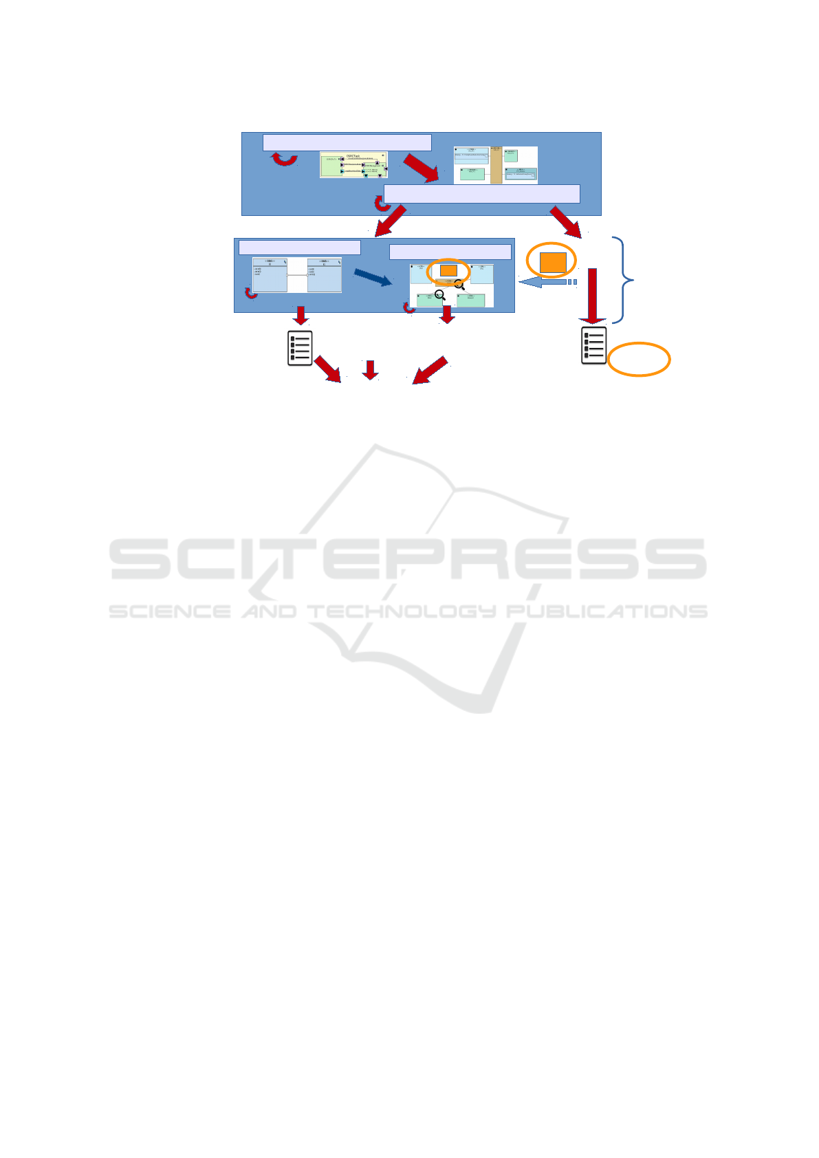
To each of these levels, as shown in Figure 2, is as-
sociated a separate panel. The method associated to
these levels explains how to take hardware/software
partitioning decisions at a high level of abstraction
and to regularly validate these decisions during soft-
ware development (Li et al., 2018).
Software tasks for the partitioning model are cap-
tured within the functional abstraction level, and soft-
ware tasks used in deployments are captured in the
software design abstraction level. In both partition-
ing and deployment, the computation part of tasks is
then deployed to processors and hardware accelera-
tors, and the communication and storage parts are de-
ployed to buses and memories.
TTool allows verification and fast simulation for
the digital part but also cycle bit accurate virtual
prototyping on a Multi-Processor System-on-Chip
(MPSoC) based on the SoCLib (SocLib consortium,
2003) public domain library written in SystemC.
As SystemC-AMS is an extension to SystemC, the
choice of this tool for integrating analog/mixed sig-
nal components was natural.
4 INTEGRATION OF ANALOG
COMPONENTS
In the following, we show how TDF concepts can be
integrated into a high-level modeling and virtual pro-
totyping tool, while maintaining as far as possible the
idea of correct-by-construction code generation. Fig-
ure 2 uses orange circles to explain how the method-
ology described above has to be adapted to AMS
components in TTool. Hardware parts, shown on the
lower right, can be simulated with a cycle-accurate
precision. Analog/Mixed Signal components are not
represented on the partitioning level, as the decision
to have them implemented in hardware or software
is not in the hands of the designer of the embedded
platforms. They must thus be visible in the deploy-
ment diagram, from which the hardware topcell and
the description of the mapping of software objects to
processors, memories and communication elements is
generated.
Our contribution is twofold: represent SystemC-
AMS components in the Deployment Diagram and
integrate the the communication between digital and
analog part of the platform in the prototyping code.
4.1 Graphical Representation of Analog
Components in TTool
TTool has been extended with an abstract way to
capture SystemC-AMS blocks with their DE, TDF
and converter ports. Each TDF cluster is designed
in its own panel because SystemC-AMS must calcu-
late a separate schedule (Accellera Systems Initiative,
2010) for each of them. When a TDF module is cre-
ated, it is possible to modify its attributes and param-
eters. The name and Timestep or Period (Tm) of a
module can be defined and time resolution selected.
The parameters of a TDF module such as its internal
variables or template parameters can be also set up, as
A Tool for High-level Modeling of Analog/Mixed Signal Embedded Systems
435
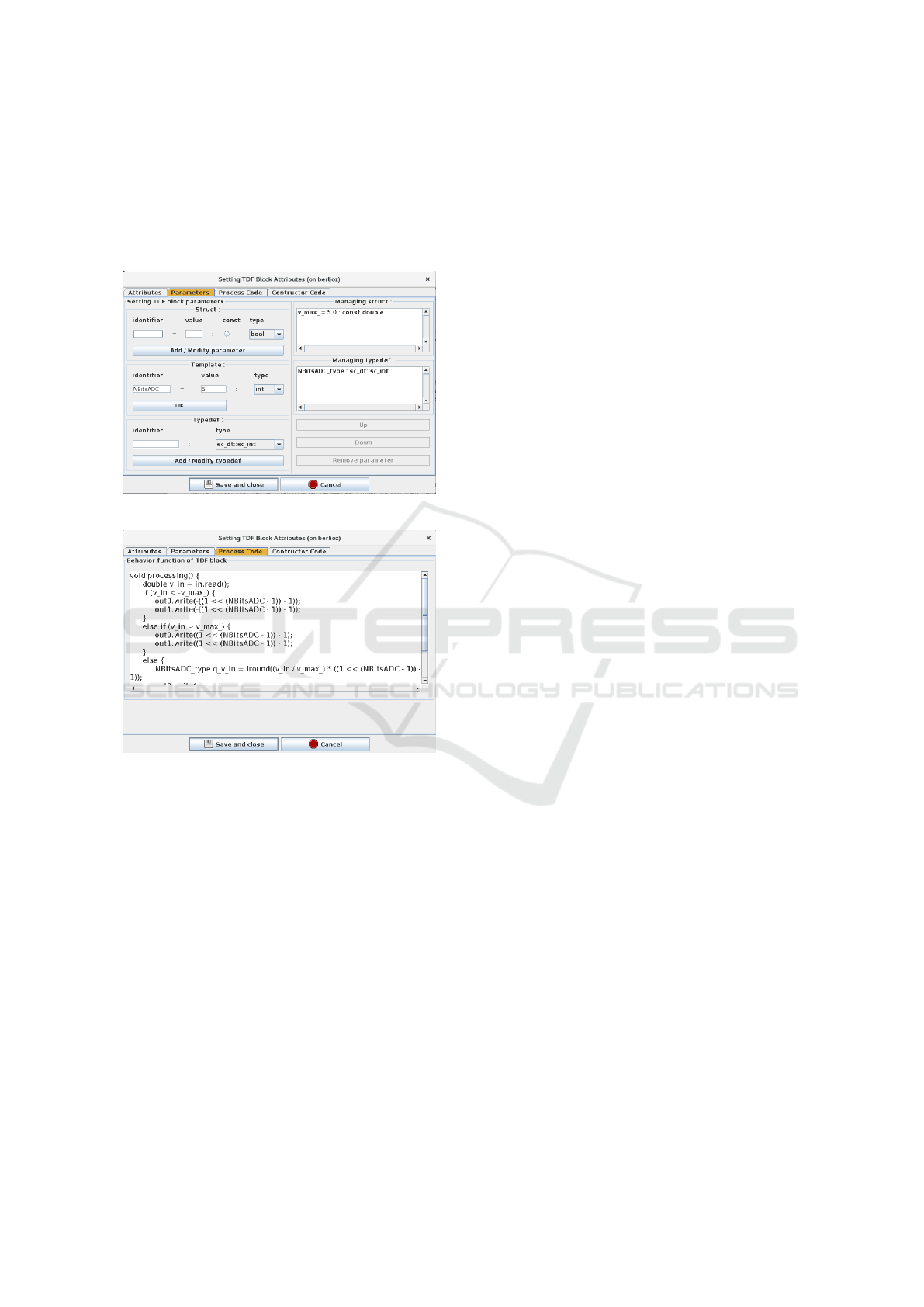
it is shown in Figure 3.
Analog components are difficult to parameterize,
since most components are more or less unique. Our
current (and temporary) solution is to offer a dia-
log window where the SystemC-AMS processing()
function can be provided, as shown in Figure 4.
Figure 3: TDF module parameters.
Figure 4: TDF module process code.
4.2 MPSoC Virtual Prototype
If the deployment model contains only SystemC-
AMS clusters, then TTool generates SystemC AMS
TDF code of the components as well as the SystemC-
AMS top cells from the mixed graphical/textual de-
scriptions, and supplies a Makefile. In case soft-
ware code is also deployed, processors / buses /
memories must also be generated. SoCLib offers
a way to describe Multi-Processor System-on-Chip
platforms with semantics based on the shared mem-
ory paradigm, where digital components are inter-
connected with VCI (VSI Alliance, 2000) interfaces.
Components can be initiators issueing requests (typi-
cally CPUs and hardware accelerators), or targets an-
swering to requests (e.g. RAM).
In order to combine SoCLib specification with
SystemC-AMS components, we have defined generic
adaptor modules that can connect SystemC-AMS
components to VCI interfaces. An adaptor is mod-
eled as a general-purpose input/output(GPIO) tar-
get component, following the modeling rules for writ-
ing cycle-bit precise SystemC simulation models for
SoCLib.described below. GPIO components are vis-
ible in the deployment diagram, and, like the other
VCI components, their interconnection to the central
VCI interconnect is represented by an arc. Click-
ing on one of the GPIO opens the corresponding
TDF cluster. Finally, the generated topcell is thus
composed of SoCLib modules and interfaces to the
SystemC-AMS clusters.
4.3 Simulation
Due to their different Model of Computation, AMS
components require to execute their simulated behav-
ior apart from the rest of the system, but regularly
synchronize with the digital platform. The SystemC
kernel is controlling the AMS kernel: the AMS ker-
nel runs continuously until it is interrupted by and
access to a converter port by a TDF cluster. When
the TDF module accesses its input converter port, the
DE simulation time advances until it is equal to the
TDF simulation time of the input converter port. If
later an access to an output converter port occurs with
a TDF simulation time that is less than the new DE
simulation time, a time synchronization issue occurs.
To avoid this situation, the TDF simulation time of
the output converter ports always needs to be greater
or equal than the DE simulation time. This prob-
lem was exposed in (Andrade et al., 2015). Since
model-driven approaches expect to ideally provide
model validation before code generation (and thus
simulation), we propose a way to statically identify
synchronization problems (Cortés Porto, 2018). The
schedulability of the analog part is validated using
the schedulability check of SystemC-AMS (Lee and
Messerschmitt, 1987a), before code is generated.
5 CASE STUDY: ROVER
A rover system, intended to assist rescuers to find vic-
tims buried in rubble, consists of four components:
central control and motor control and the two sensors,
a distance sensor and a temperature sensor.
In the rover case study already published in (Ge-
nius et al., 2018), we replace the two sensors by more
realistic analog models (TDF still being an abstraction
of the analog behavior). Central and motor control are
still modeled as digital components, whereas the two
sensors are modeled as independent TDF clusters. As
MODELSWARD 2019 - 7th International Conference on Model-Driven Engineering and Software Development
436
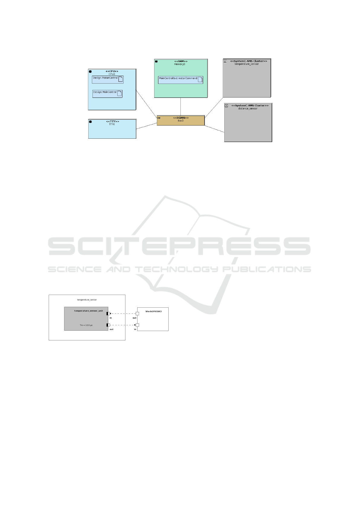
Figure 5: Deployment Diagram model of the rover.
the partitioning decision has already been taken for
the analog blocks, they are not part of functional and
partitioning views.
5.1 Software Design
Figure 5 shows the deployment diagram where the
two software tasks (MainControl, motorControl)
are mapped onto the CPU, the channel between the
tasks on the memory. TDF clusters appear as gray
boxes along with digital components, interconnected
to the central (digital) interconnect through GPIO
components as detailed below;
5.2 Diagrams for TDF Clusters
SystemC-AMS Component Diagram panels are
shown in Figures 6 and 7.
Figure 6: Temperature sensor model.
The temperature sensor cluster is composed of one
single TDF module. The behavior of this module,
which is a simplification of the actual behavior of
a temperature sensor, is described as SystemC-AMS
code. It depends on the value received on its input
port in, which is connected to the digital components
of the system via a GPIO2VCI component. A value of
0 means that the temperature sensor should be turned
off. If a value different from 0 is received, then the
temperature sensor will generate random integer val-
ues from 0 to 30, representing the temperature cur-
rently measured. Temperature values are written to
the output port out of the module which is also con-
nected to the GPIO2VCI component. Hence, the val-
ues will be available to be read by the digital com-
ponents of the system. The temperature sensor will
operate in timesteps of 10 µ s.
The distance sensor cluster shown in Figure 7, is
composed of three distinct TDF modules, each mod-
eling an ultrasonic sensor. These are connected to a
DE module modeling the controller which reads val-
ues from each of the ultrasonic sensors and writes a
value to the GPIO2VCI component, depending on the
value obtained from its input port in.
A value of 0 makes it read from the
ultrasonic_sensor_left, a value of 1 from
the ultrasonic_sensor_front, a value of 2 from
the ultrasonic_sensor_right. Each ultrasonic
sensor produces random values (from 0 to 12) in
timesteps of 100 ns. The behavior of this cluster is
a simplification of the behavior of a real distance
sensor, since the focus of the paper is mostly on
the communication between the digital and analog
aspects.
5.3 Interaction of Analog Blocks with
the Software Design Level
On the software side of the model, two blocks have
been created to represent the MotorControl and the
MainControl (not shown). They represent the soft-
ware design level shown on the lower left of Figure 2.
In contrast to the purely digital model of the same ap-
plication, the functional blocks pertaining to the sen-
sors are no longer represented in the block diagram,
since they are represented by analog blocks captured
in two separate SystemC-AMS panels.
Both blocks communicate with each other through
a signal motorCommand which is sent by the
MainControl to the MotorControl and contains two
parameters for the right and left velocity. The blocks
A Tool for High-level Modeling of Analog/Mixed Signal Embedded Systems
437
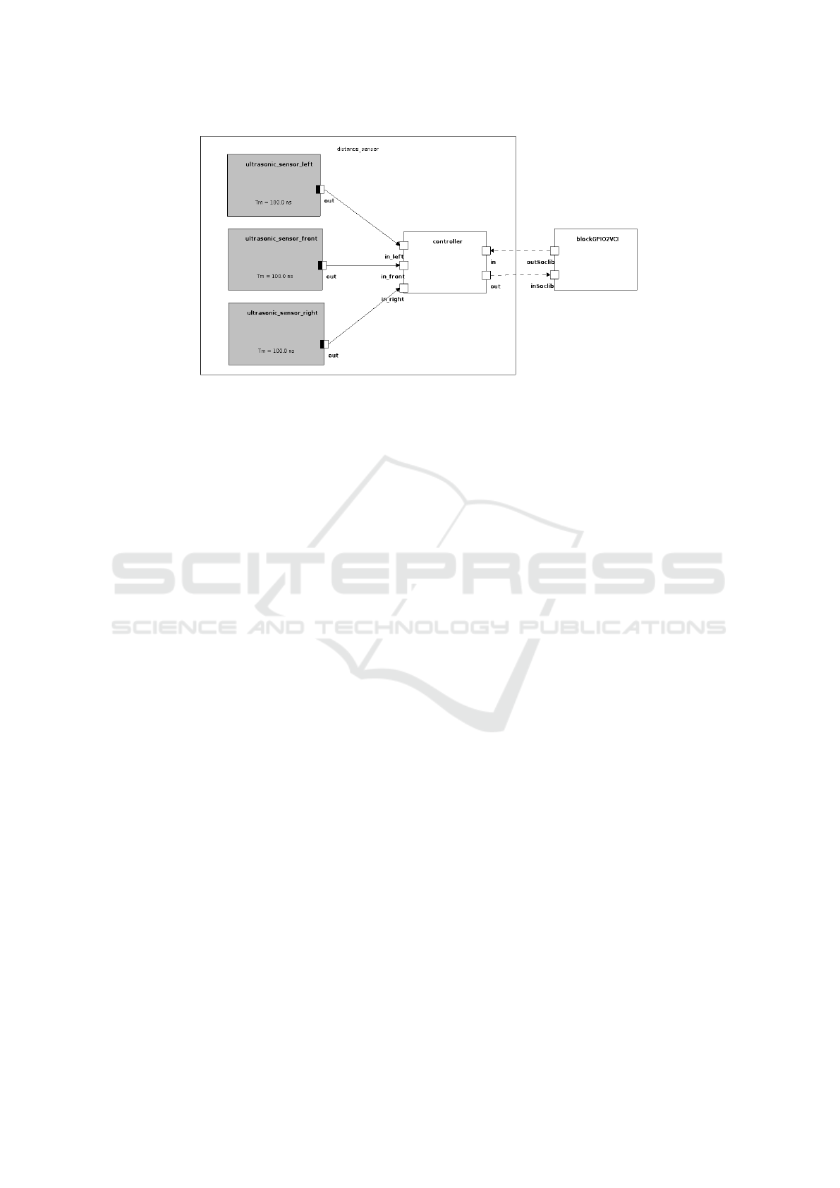
Figure 7: Distance sensor model.
also initialize internal attributes.
The state machine of the MotorControl block
has only one state startMotor. It receives the two
velocity parameters from the motorCommand signal
and waits for some random time between 10 and 20
clock cycles. The state machine of the MainControl
block is shown in Figure 8. In the following, we
provide a more detailed description of the states,
specially the ones that interact with the TDF clus-
ters. By executing software functions, the CPU of
the digital platform is able to write or read values
from the analog components. During the first state
startController, the variable sensorOn, initial-
ized to 0 in the MainControl block, and written to
the GPIO2VCI component connected to the temper-
ature sensor cluster. The C code inserted into the
startController state, shown in the upper part of
Figure 9, turns the temperature sensor unit module
off. Figure 10 shows the local host console output.
In the next state readDistanceSensor, each ul-
trasonic sensor is selected in turn by writing a differ-
ent value to the distance sensor cluster, then the sensor
output is read and the read value is printed to the TTY
component of the model, as shown in the code from
Figure 9.
After this, the next state calculateDistance
simulates how the velocity of the rover is calculated
based on the front distance that was read as shown
in the state diagram of Figure 8. If the distance was
large (greater than 8), the state condition will lead to
state0 and a normal speed would be set (a value of
5). If the distance was between 3 and 8, it would go to
state1 and a low speed (a value of 2) would be set.
In this case, since the front distance was 2 less than
3, the calculateDistance state condition will lead
to state2. Here the state variable is set to 2. Then
it proceeds to the controlTempSensor state, where,
sinc state = 2, sensorOn is set to 1. In the subse-
quent setTempSensor state, the temperature sensor
unit is turned on or off by writing the value of the
sensorOn variable to the temperature sensor cluster
as shown in the lowest part of Figure 9. In the output
from the local host machine, we observe that at time
3196116 ns, a value of 1 is written to the GPIO2VCI
component. At this point the temperature sensor unit
is turned on.
In the following states, the rover will measure the
temperature. Depending on the state variable, the
turnDecision state will decide if the rover needs to
turn or not. If the distance is greater or equal than 3,
then the state variable will be 0 or 1, and the rover
will neither measure temperature nor turn. In our case
the distance is 2 and the state variable is 2, so it goes
to the next state measureTemp.
In the measureTemp state, the temperature sensor
cluster is read and the temperature is printed to the
TTY, as shown in the lowest part of Figure 9. In the
local host console (Figure 10), at time 3935019 ns a
value of 21 is read. The output on the TTY is shown
in the lower red rectangle from Figure 11.
The dodgeObstacle state calculates whether the
rover needs to turn left or right, based on the distance
measured from the left and right ultrasonic sensors; it
will set the velocity of the left or right motors accord-
ingly. After turning left or right, the motorCommand
signal is sent to the motor control state machine, so
that it can adjust the velocity of the motors. Finally,
the main control state machine loops again to the
readDistanceSensor state to start a new cycle.
MODELSWARD 2019 - 7th International Conference on Model-Driven Engineering and Software Development
438
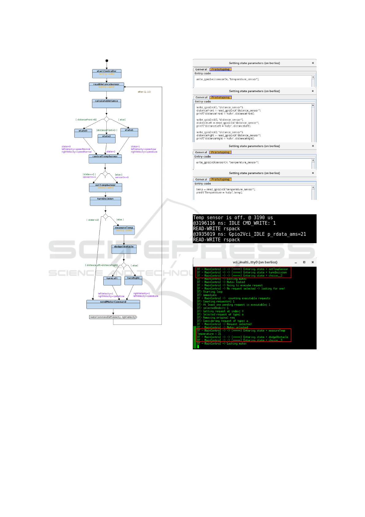
Figure 8: Main control state machine with entry
code in the startController, readDistanceSensor,
setTempSensor and measureTemp states.
6 CONCLUSION AND
PERSPECTIVES
The paper shows the integration of SystemC-AMS
(TDF) components into a multi-level modeling tool
for complex embedded systems. Virtual prototyping
can be performed from the last refinement stage, tak-
ing into account both analog and digital parts of the
system. To this end, a library was created to provide
read and write functions between the digital and ana-
log components, which can be used in State Machine
Figure 9: Entry code in the Prototyping window tab.
Figure 10: Simulation output from host machine console.
Figure 11: Simulation output from the TTY component
console - setTempSensor and measureTemp state.
Diagrams modeling software behaviors. Code gener-
ation of TTool was extended to SystemC-AMS code.
Yet, in order to use these functions, entry code in
C language needs to be inserted in the state blocks
of the TTool diagram. In the future, this should be
replaced by specific read and write operators.
The feedback of simulation results is currently
still limited to the digital part and only semi-
automatic. Automating and extending this mecha-
nism to the entire system would enable us to propose
A Tool for High-level Modeling of Analog/Mixed Signal Embedded Systems
439

a full design space exploration environment for Ana-
log/Mixed Signal systems.
REFERENCES
Abrial, J.-R. (2010). Modeling in Event-B: system and soft-
ware engineering. Cambridge University Press.
Accellera Systems Initiative (2010). SystemC AMS exten-
sions Users Guide, Version 1.0. Accellera Systems
Initiative.
Andrade, L., Maehne, T., Vachoux, A., Ben Aoun, C.,
Pêcheux, F., and Louërat, M.-M. (2015). Pre-
Simulation Formal Analysis of Synchronization Is-
sues between Discrete Event and Timed Data Flow
Models of Computation. In Design, Automation and
Test in Europe, DATE Conference.
Apvrille, L. (2011). Webpage of TTool.
Balarin, F., Watanabe, Y., Hsieh, H., Lavagno, L.,
Passerone, C., and Sangiovanni-Vincentelli, A. L.
(2003). Metropolis: An integrated electronic system
design environment. IEEE Computer, 36(4):45–52.
Beyond Dreams Consortium (2008-2011). Be-
yond Dreams (Design Refinement of Embed-
ded Analogue and Mixed-Signal Systems).
http://projects.eas.iis.fraunhofer.de/beyonddreams.
Bouquet, F., Gauthier, J.-M., Hammad, A., and Peureux, F.
(2012). Transformation of SysML structure diagrams
to VHDL-AMS. In 2012 Second Workshop on Design,
Control and Software Implementation for Distributed
MEMS, pages 74–81. IEEE.
Concepcion, A. I. and Zeigler, B. P. (1988). DEVS for-
malism: A framework for hierarchical model devel-
opment. IEEE Transactions on Software Engineering,
14(2):228–241.
Cortés Porto, R. (2018). Integration of SystemC-AMS sim-
ulation platforms into TTool. Master’s thesis, Tech-
nische Universität Kaiserslautern.
Davare, A., Densmore, D., Meyerowitz, T., Pinto, A.,
Sangiovanni-Vincentelli, A., Yang, G., Zeng, H., and
Zhu, Q. (2007). A next-generation design framework
for platform-based design. In DVCon, volume 152.
Gamatié, A., Beux, S. L., Piel, É., Atitallah, R. B., Etien,
A., Marquet, P., and Dekeyser, J.-L. (2011). A model-
driven design framework for massively parallel em-
bedded systems. ACM Trans. Embedded Comput.
Syst, 10(4):39.
Genius, D., Li, L. W., and Apvrille, L. (2018). Multi-level
Latency Evaluation with an MDE Approach. In MOD-
ELSWARD.
H-Inception Consortium (2012-2015). Hetero-
geneous Inception Project. https://www-
soc.lip6.fr/trac/hinception.
Herrera, F. and Villar, E. (2007). A framework for heteroge-
neous specification and design of electronic embedded
systems in systemc. ACM Transactions on Design Au-
tomation of Electronic Systems (TODAES), 12(3):22.
IEEE (2011). SystemC. IEEE Standard 1666-2011.
Lee, E. A. and Messerschmitt, D. G. (1987a). Static
Scheduling of Synchronous Data Flow Programs for
Digital Signal Processing. IEEE Transactions on
Computers, C-36(1):24–35.
Lee, E. A. and Messerschmitt, D. G. (1987b). Synchronous
data flow. Proceedings of the IEEE, 75(9):1235–1245.
Li, L. W., Genius, D., and Apvrille, L. (2018). Formal
and virtual multi-level design space exploration. In
MODELSWARD, Springer Communications in Com-
puter and Information Science, vol 880, pages 47–71.
Niaki, S. H. A., Jakobsen, M. K., Sulonen, T., and Sander,
I. (2012). Formal heterogeneous system modeling
with systemc. In Specification and Design Languages
(FDL), 2012 Forum on, pages 160–167. IEEE.
Ptolemy.org, editor (2014). System Design, Modeling, and
Simulation using Ptolemy II.
Selic, B. and Gérard, S. (2013). Modeling and Analysis
of Real-Time and Embedded Systems with UML and
MARTE: Developing Cyber-Physical Systems. Else-
vier.
SocLib consortium (2003). The SoCLib project: An inte-
grated system-on-chip modelling and simulation plat-
form. Technical report, CNRS. www.soclib.fr.
Taha, S., Radermacher, A., and Gérard, S. (2010). An
entirely model-based framework for hardware design
and simulation. In DIPES/BICC, volume 329 of IFIP
Advances in Information and Communication Tech-
nology, pages 31–42. Springer.
Vachoux, A., Grimm, C., and Einwich, K. (2003). Analog
and mixed signal modelling with SystemC-AMS. In
ISCAS (3), pages 914–917. IEEE.
Vidal, J., de Lamotte, F., Gogniat, G., Soulard, P., and
Diguet, J.-P. (2009). A co-design approach for embed-
ded system modeling and code generation with UML
and MARTE. In DATE, pages 226–231. IEEE.
VSI Alliance (2000). Virtual Component Interface Standard
(OCB 2 2.0).
Zhu, J., Sander, I., and Jantsch, A. (2010). Hetmoc: Hetero-
geneous modelling in systemc. In Specification & De-
sign Languages (FDL 2010), 2010 Forum on, pages
1–6. IET.
MODELSWARD 2019 - 7th International Conference on Model-Driven Engineering and Software Development
440
