
A Hybrid Method for Remote Eye Tracking using RGB-IR Camera
Kenta Yamagishi and Kentaro Takemura
Graduate School of Engineering, Tokai University, Hiratsuka, Japan
Keywords:
Eye-tracking, RGB-IR Camera, 3D Eye Model.
Abstract:
Methods for eye tracking using images can be divided largely into two categories: Methods using a near-
infrared image and methods using a visible image. These images have been used independently in conventional
eye-tracking methods; however, each category of methods have different advantageous features. Therefore, we
propose using these images simultaneously to compensate for the weak points in each technique, and an RGB-
IR camera, which can capture visible and near-infrared images simultaneously, is employed. Pupil detection
can yield better results than iris detection because the eyelid often occludes the iris. On the other hand, the
iris area can be used for model fitting because the iris size is constant. The model fitting can be automated
at initialization; thus, the relationship between the 3D eyeball model and eye camera is solved. Additionally,
the positions of the eye and gaze vectors are estimated continuously using these images for tracking. We
conducted several experiments for evaluating the proposed method and confirmed its feasibility.
1 INTRODUCTION
In eye-tracking research, there are several impor-
tant topics, one of which is the estimation of point-
of-gaze. Many researchers have proposed various
estimation methods with high accuracy(Morimoto
and Mimica, 2005; Guestrin and Eizenman, 2006).
Furthermore, calibration methods for computing a
point-of-gaze and visual axis have also been discus-
sed(Ohno et al., 2002; Nagamatsu et al., 2010). Re-
cent works involve the use of an eye-tracking de-
vice in applications such as a head-mounted dis-
plays(Toyama et al., 2012) and other devices used in
day-to-day activities(Kassner et al., 2014). In addi-
tion to wearable eye trackers, a remote eye tracker is
also desired for daily applications. For example, a re-
mote eye tracker can be used with digital signage, and
we can measure the region of interest and the effect of
the display contents.
We also have studied several eye-tracking met-
hods including the 3D point-of-gaze(Takemura et al.,
2014a) and corneal imaging(Takemura et al., 2014b).
Additionally, in our previous research, we propo-
sed pupil and iris tracking using an RGB-IR ca-
mera(Yamagishi and Takemura, 2017), and we achie-
ved model-based tracking. However, the previous
method was proposed for wearable eye tracker; hence,
it is necessary to maintain the relationship between
the camera and the eyeball during measurement. The-
refore, we propose a method to estimate the eyeball
position and the eye tracking for a remote and glint-
free eye-tracking method using an RGB-IR camera.
The limbus is suitable for model fitting because the
size is constant. Strictly speaking, there is an indivi-
dual difference in the size of human eyes, but we use
a 3D model average size(Grand and Hage, 1980) for
the model-based approach. Therefore, the eyeball po-
sition can be computed using the limbus. However,
the eyelids often occlude part of the iris, which is a
disadvantage. On the other hand, pupil size is chan-
ged by several factors such as illumination conditions
and mental state, and thus it is difficult to use it in
model fitting. However, pupil area can be detected ea-
sily using a near-infrared image, and occlusion rarely
occurs. Therefore, visible and infrared images are
used simultaneously to compensate for weak points
in each image as a hybrid eye-tracking method.There
is two main contribution in this research; first, we
implemented a method for iris detection by conver-
ting to polar coordinates based on a detected pupil re-
gion with an RGB-IR camera for eye model fitting.
In our previous research, the limbus was input manu-
ally for computing the initial relationship. Therefore,
it was necessary to initialize without user operation.
Second, the eye-tracker has tolerance for head mo-
vements as a remote eye-tracking. We estimated eyes
position and gaze vector by detecting dual eyes using
the pupils and 3D eyeball models. We conducted se-
veral experiments for evaluating the accuracy of the
point-of-gaze and confirmed the feasibility of the re-
Yamagishi, K. and Takemura, K.
A Hybrid Method for Remote Eye Tracking using RGB-IR Camera.
DOI: 10.5220/0007582705910596
In Proceedings of the 14th International Joint Conference on Computer Vision, Imaging and Computer Graphics Theory and Applications (VISIGRAPP 2019), pages 591-596
ISBN: 978-989-758-354-4
Copyright
c
2019 by SCITEPRESS – Science and Technology Publications, Lda. All rights reserved
591

(a)
(b)
(c)
Figure 1: Blocks of binary images (a) are labeled by con-
nected component labeling (b); the pupil area (c) is estima-
ted using the degree of circularity.
mote eye-tracking.
2 PUPIL AND IRIS DETECTION
2.1 Pupil Detection using the Degree of
Circularity
Previously, we proposed hybrid eye tracking using an
RGB-IR camera, and the relationship between the eye
camera and eyeball was computed using the limbus.
However, the limbus was selected manually. Thus,
the limbus detection is implemented as an auto ini-
tialization in this paper. The details of pupil and
iris detection are described below. Stable tracking
of the pupil has been studied previously by many re-
searchers(Fuhl et al., 2016) using near-infrared ima-
ges. Thus, the pupil is tracked using the near-infrared
image captured by the IR camera to compute the pose
of the eye, and the center of the pupil is used for de-
tecting the optical axis of the eye. The procedure for
detecting the center of the pupil is described below.
1. Convert the near-infrared image to a binary image
(Figure 1(a))
2. Apply the connected component labeling to the
binary image (Figure 1(b))
3. Compute the degree of circularity for each divided
area
4. Select the area with the highest degree of circula-
rity as the pupil area
5. Compute the center of the pupil using elliptical
approximation (Figure 1(c))
In our implementation, we calculated the degree of ci-
rcularity for each labeled area to detect the pupil area,
as proposed by Hausner(Haubner, 1966). The degree
of circularity ψ is computed by the following equa-
tion:
ψ =
4πS
L
2
, (1)
where S and L are the area and perimeter of the pupil,
respectively. After detecting the pupil area, the pupil
is tracked by searching the neighboring area of the
previously known position of the pupil.
Pc
-a
b
l
-b
a
f
2
f
1
r
e
-l
y
x
x
y’
x
2
y
2
c
(a) (b)
y’
r
e
f
2
f
1
(x, y)
(x, y)
Figure 2: Deriving the equation of an ellipse.
2.2 Iris Detection using Polar
Transformation
Tian et al.(Tian et al., 2012) proposed iris detection
using polar transformation of the center of the pu-
pil. This allowed the limbus to be detected as a
straight line. However, the iris was assumed to be
a perfect circle in the aforementioned study. In this
study, we developed an improved method in which
polar transformation can also be applied for iris de-
tection when the iris is observed as an ellipse. For ap-
plying polar transformation to an ellipse, focal length
c =
√
a
2
+ b
2
, eccentricity e = c/a and semi-latus rec-
tum l = (a
2
−c
2
)/a are required. These are compu-
ted using the pupil center P
c
, semi-major axis a and
semi-minor axis b as shown in Figure 2(a). There-
fore, the relationship between the rectangular coordi-
nate system (x, y) and polar coordinate system (r
e
,θ)
is given as follows:
(
x = f
2x
−sr
e
cos(θ + φ)
y = f
2y
−sr
e
sin(θ + φ),
(2)
where r
e
and φ are the distance from the focal point
to the elliptic curve and the slope of the ellipse, re-
spectively, as shown in Figure 2(b), and r
e
is compu-
ted using the following equation:
r
e
=
l
1 + ecosθ
. (0 ≤ θ ≤ 359) ∈ N (3)
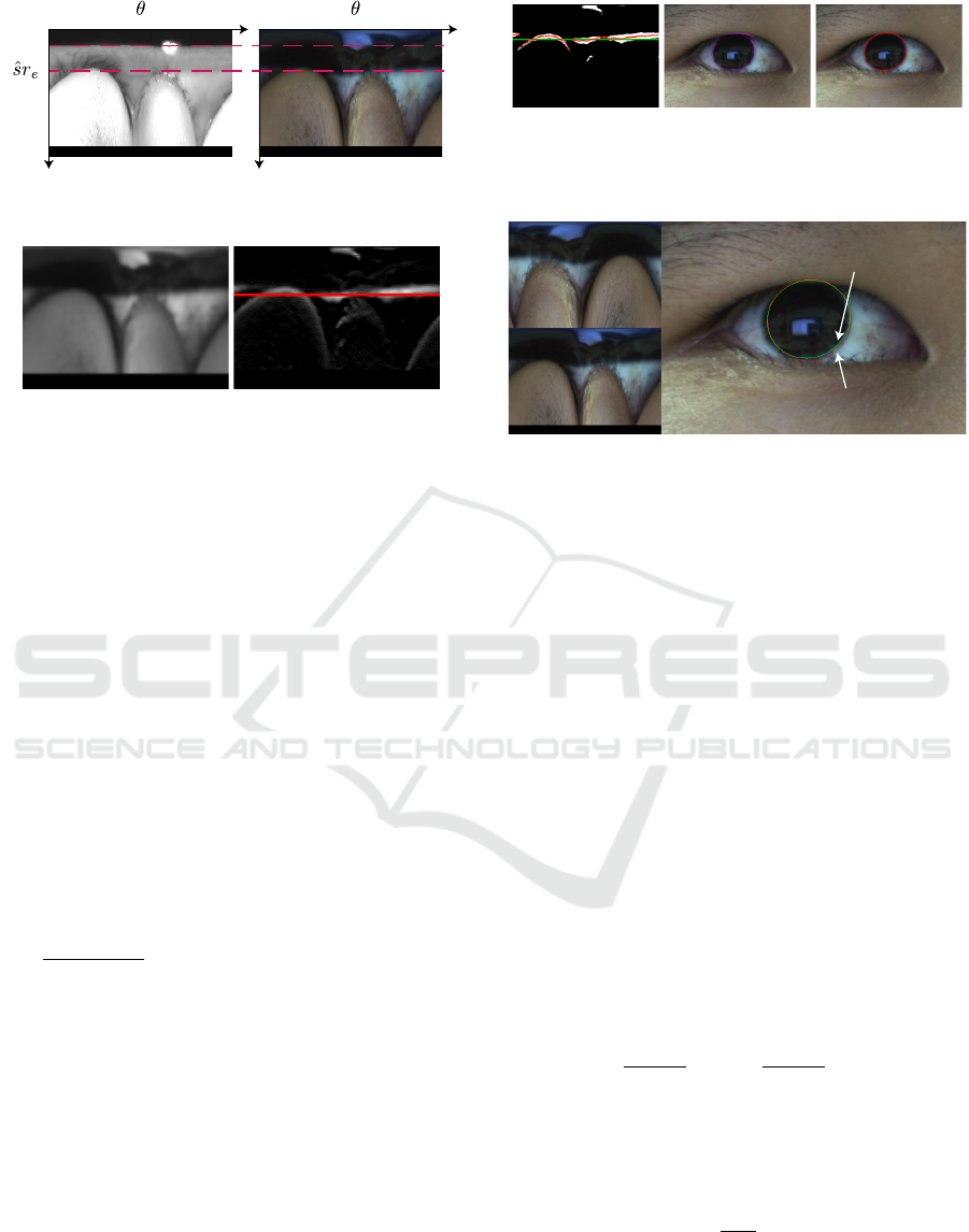
Figure 3 shows the transformed eye images in the po-
lar coordinate system, and values of each column are
computed by changing scale s of Equation 2. When
s = 1, the ellipse is normalized as b = 1. The pupil
edge on the transformed image is detected as s
min
r
e
.
Then, the color image is converted to the HSV color
space, and the brightness image is generated. Next,
we apply a bilateral filter to the brightness image, as
shown in Figure 4(a). The differential images (Figure
4(b)) are computed for vertical variations, and the
sum of the differential values are computed in each
sr
e
between 0 to 359 deg. The scale ˆs for largest co-
VISAPP 2019 - 14th International Conference on Computer Vision Theory and Applications
592
0 359 0 359
s
min
r
e
Figure 3: Transformed eye images in the polar coordinate
system for detecting iris and pupil areas.
(a)
(b)
Figure 4: Brightness (a) of the eye image in HSV color
space, and the differential image (b).
lumn sr
e
is given by
ˆs = argmax
s∈N
(
∑
θ
( f (sr
e
,θ) − f (sr
e
−1,θ))), (4)
where f (sr
e
,θ) is the brightness value for pixel
(sr
e
,θ). The red line shows the largest column, and
the limbus is estimated as shown in Figure 4(b).
Theoretically, the edges of the limbus are extrac-
ted as straight lines. However, in reality, some dis-
tortion exists. The distortion is caused mainly by the
difference between the centers of the iris and pupil.
The center of the iris is different from the center of
the pupil, as has been reported(Wilson et al., 1992).
Thus, it is necessary to detect the limbus in the polar
coordinate system for accurate detection of the iris.
Consequently, recalculation is required for estimating
the optimal limbus. Binary images (Figure 5(a)) are
converted by using the following threshold:
T =
∑
θ
f ( ˆsr
e
,θ)
∑
θ
χ( ˆsr
e
,θ)
, χ( ˆsr
e
,θ) =
(
1 ( f ( ˆsr
e
,θ) 6= 0)
0 ( f ( ˆsr
e
,θ) = 0).
(5)
The connected components are searched around ˆsr
e
,
and the points of the connected components are pro-
jected by the input image, as shown in Figure 5(b),
and the iris is detected based on these points using the
least-square method and RANSAC, as shown in Fi-
gure 5(c). Figure 6 shows the comparison of images
generated by polar transformation of a perfect circle
and of an ellipse. It is observed that the edge of the
iris has high linearity even when an ellipse is subject
to polar transformation, and the proposed method can
fit limbus well.
(a)
(b)
(c)
Figure 5: The binary image (a) for searching connected
components, the image (b) that the points on the compo-
nents are projected on, and the detected iris area (c) using
the least-square method.
(a)
(b)
(c)
Iris detection using polar
transform with perfect circle (red)
Iris detection using polar
transform with ellipse (green)
Figure 6: Comparative results between using a perfect circle
and an ellipse.
2.3 3D Eyeball Model Fitting
The 3D model of the eye consists of the corneal and
eye spheres, as shown in Figure 7. The parameters
of this model have been determined by anatomical
data(Snell and Lemp, 1997), as shown in Table 1.
First, we the calculated depth and attitude of the eye
using Nishino’s method(Nishino and Nayar, 2006).
This method is important, so it is briefly described
in section 2.3.1. Next, we estimated the center of the
eyeball for both eyes and the distance of both eyes.
2.3.1 Estimating the Pose of the Eyes
First, the initial position between the camera center
and the eye is computed using the model. Then, the
iris, along with both corners of the eye, are registered
on the color image, and the center of the iris (i
Lx
,i
Ly
)
is drawn on the color image using an elliptical approx-
imation. The 3D center of the limbus P can then be
computed as:
P =
(d + f )
i
Lx
−cx
f
,(d + f )
i
Ly
−cy
f
,(d + f )
T
,
(6)
where (cx,cy) and f are camera parameters (the op-
tical centers in the image coordinates and the focal
length, respectively). The distance d between the cen-
ter of the limbus and the image plane is calculated as
d = f
r
L
r
max
, (7)
where r
max
is the major radius of the ellipse. The op-
tical axis of the eye is given by
g = [sin(τ)sin(φ), −sin(τ)cos(φ),−sin(τ)]
T
, (8)
A Hybrid Method for Remote Eye Tracking using RGB-IR Camera
593
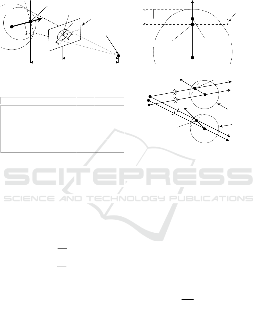
d Distance between image plane and the center of iris
φ
τ
r
min
r
max
f Focus length
O Center of camera lense
Image plane
g Optical axis
Corneal sphere
Eyeball
(i
Lx
, i
Ly
) Iris center on image plane
P Center of the pupil
r
L
E
Figure 7: Geometric 3D eye model consisting of the eye
sphere and the corneal sphere for tracking the pupil and iris.
Table 1: Anatomical parameters for 3D eye model.
Description Def. Parameter
Radius of the eye sphere r
E
12.1 mm
Radius of the corneal sphere r
C
7.78 mm
Radius of the limbus r
L
5.6 mm
Distance from the cornea’s center
d
CE
5.2 mm
to the eyeball’s center
Distance from the pupil’s center
d
PC
5.6 mm
to the cornea’s center
where φ is the rotation of the limbus ellipse and τ is
the angle of the tilt of the limbus plane with respect to
the image plane. The estimated ellipse corresponds to
two poses of the eye, such as upward and downward
attitude, and the pose cannot be determined uniquely.
Thus, the camera position relative to the face is used
for determination.
2.3.2 Estimating the Distance between Eyeballs
The center of the cornea C and the center of the eye
E are determined using the following equations, re-
spectively:
C = −d
PC
g
||g||
+ P, (9)
E = −d
CE
g
||g||
+ C. (10)
The centers of the eyeballs E
L
and E
R
are computed
for each eye, and the distance d
EE
between the ey-
eballs is calculated. These parameters are used for
the position tracking mentioned in section 3 as a con-
straint.
3 3D POSITION TRACKING FOR
EYES
When we implement our algorithm in a head-mounted
eye tracker, the center of the cornea calculated in the
g
d
IP
Distance of between
actual and entrance pupil
E
3.05
3.60
P
The center of real pupil
P
I
The center of entrance pupil
Figure 8: The entrance and exit pupil of the eye.
g
L
g
R
O
R
O
L
O
V
PL
V
PR
E
L
E
R
P
IL
P
IR
The right eye
The left eye
Figure 9: Geometrical constraint of the eyeball position.
initialization is used for tracking. However, the eye
position is changed when the remote eye tracker is
employed, and thus a continuous position estimation
is required. Therefore, the pupil and iris are used for
estimating the pose and the position of the eye, re-
spectively. The details of the continuous position esti-
mation are as follows. First, the pupil region is extrac-
ted, and the optical axis g is estimated using the pupil
ellipse’s elevation mentioned in section 2. The vec-
tors from the camera lens to the pupil centers are de-
fined as V
PR
and V
PL
, and the vector passing through
the centers of the pupils are defined as P
IR
and P
IL
and are observed approximately 0.55 mm ahead of the
real pupil position by the refraction of the cornea as
shown in Figure 8. Furthermore, the eyeball centers
E
R
and E
L
are computed using the anatomical para-
meters d
IP
, d
PC
, and d
CE
. The vectors V
PR
and V
PL
are shifted parallel by d
IP
as shown in Figure 9. The
shifted origins are defined as O
L
and O
R
by the follo-
wing equations,
O
R
= O −
g
R
||g
R
||
(d
IP
+ d
PC
+ d
CE
), (11)
O
L
= O −
g
L
||g
L
||
(d
IP
+ d
PC
+ d
CE
), (12)
and the actual positions of the eyes are located on two
vectors defined as follows:
E
R
= O
R
+tV
PR
, (13)
E
L
= O
L
+ µV
PL
. (14)
VISAPP 2019 - 14th International Conference on Computer Vision Theory and Applications
594
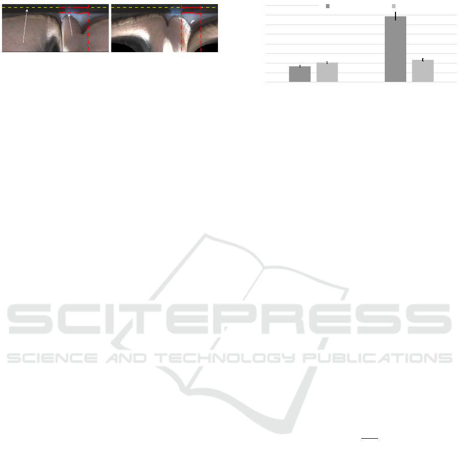
L
R
:Extracted limbus edge
R
R
:Projected limbus edge
Figure 10: Re-projected limbus R and extracted limbus L
are displayed on transformed images for right and left eyes.
The eye position cannot be calculated by closed-form
solution. However, when the distance between the
eyes is defined as d
EE
, the distance is used as a cri-
teria for estimating the position. Additionally, the
positions of the eyes are located on these vectors,
and thus, the searching area is restricted. When the
candidates for the eye positions are selected, the re-
projected limbus are matched to the actual limbus on
the image. Figure 10 shows the extracted limbus and
the re-projected limbus from candidates for both eyes.
Limbus edges that have the brightness higher than
threshold are used for evaluation. The coordinates of
the extracted limbus edges from the image are L
R
and
L
L
in polar coordinates, and the polar coordinates of
the re-projected limbus are R
R
and R
L
. The positions
of the eyes are estimated using the following evalua-
tion formula:
{
ˆ
t, ˆµ
}
= argmin
t,µ
{k
L
R
−R
R
k
+
k
L
L
−R
L
k}
. (15)
The computed optimal parameters
ˆ
t and ˆµ are substi-
tuted for equation 13 and 14, respectively. Finally, the
eyeball centers can be estimated in each frame.
4 EVALUATION EXPERIMENT
We performed a experiment for confirming the tole-
rance of head movements by measuring the accuracy
of the point-of-gaze. The experiment is conducted un-
der the experimental setup. Nine(3×3) markers are
displayed at 480 mm × 240 mm intervals on the 27-
inch monitor. The camera was calibrated using a ci-
rcular grid in advance, and the intrinsic parameters
were known. For estimating the point-of-gaze, the ge-
ometric relationship between the camera and the mo-
nitor are required. Therefore, retro-reflective markers
were attached to the camera and the monitor, and the
geometric relationship was solved by the motion cap-
ture system as the hardware calibration. Furthermore,
the visual axis was calculated from the optical axis
determined using the 3D eyeball model using the an-
gle calculated by the one-point calibration (user ca-
libration), and the point-of-gaze was computed as an
intersection between the visual axis and the monitor.
Research participants stared at nine points in each ex-
periment, and ten images were captured at each point
for calculating the average error.
0
1
2
3
4
5
6
7
8
Fixed head Non-contact
Angular error [deg]
Previous method Proposed method
1.66
6.87
2.33
2.04
Figure 11: The average error of the estimated point-of-gaze
with and without the chin rest
There were ten research participants aged 20–23
years in this experiment. Figure 11 shows the average
error and the standard error of the estimated point-of-
gaze with and without the chin rest, when our previ-
ous method(Yamagishi and Takemura, 2017) and the
proposed method are applied. The error of the esti-
mated point-of-gaze was increased without the chin
rest in our previous method. In contrast, the compu-
ted accuracies under the two experimental conditions
are very similar in the proposed method, and we con-
firmed that the proposed method has a tolerance for
head movements.
5 DISCUSSION
In this section, the elevation of the camera is discus-
sed through additional experiment. We prepared three
camera conditions, large to small elevation, for evalu-
ating the influence of the camera setting. When the
pupil is detected as an ellipse, the major and minor
axes are used for detecting the pose of the eye. Ho-
wever, the inverse cosine is used for estimating the
pose as per the following equation:
τ = cos
−1
r
min
r
max
. (16)
Thus, when an ellipse is closed to a perfect circle, the
estimation error could might be increased. Therefore,
the elevation angles of the cameras were 20, 30 and,
40 deg, and the point-of-gaze was estimated with our
proposed method. In this experiment, the head is fixed
with the chin rest while estimating the point-of-gaze.
Figure 13 shows the average error and the standard er-
ror of the estimated point-of-gaze as the comparative
result. As shown by these results, accuracy is influen-
ced by the elevation of the camera. When the point-
of-gaze is calculated, the large elevation angle works
better than the small angle. Figure 12 shows how the
value of the inverse cosine depends on the ratio bet-
ween the major axis and minor axis. When the ratio
is close to one, the value of the inverse cosine varies
extremely. As a result, we can understand that a large
A Hybrid Method for Remote Eye Tracking using RGB-IR Camera
595
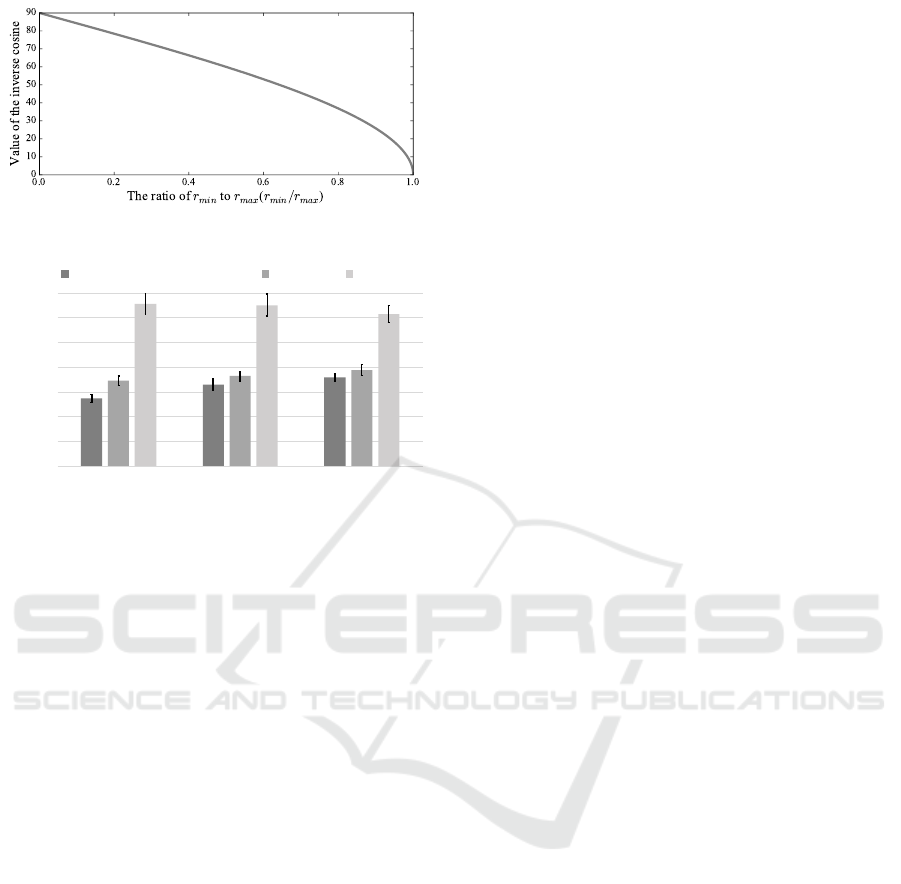
Figure 12: Variance of the inverse cosine.
0
0.5
1
1.5
2
2.5
3
3.5
A B C
Angular error [deg]
Research participants
Camera slope when 40 degree.
30 degree 20 degree
1.37
3.28
3.25
3.07
1.94
1.79
1.65
1.82
1.73
Figure 13: The average error of the estimated point-of-gaze
under three camera conditions.
elevation is required. Currently, it is difficult to mea-
sure the eye from a low angle with high accuracy, but
a low angle is needed for various applications. There-
fore, this problem should be solved in future work.
6 CONCLUSIONS
In this research, we proposed a remote eye-tracking
method, and the eyeball positions and gaze vectors
were estimated using an RGB-IR camera. The IR
image and visible image were simultaneously used to
compensate for weak points. The pupil was tracked
using the near-infrared image for estimating the pose
of the eye. Additionally, the position was estimated
using the limbus in the remote eye-tracking method.
We conducted several experiments and confirmed the
feasibility of the proposed method as a remote eye
tracker. In future work, we will solve the problem of
measurement range that is discussed above, and the
method will be used for digital signage.
REFERENCES
Fuhl, W. et al. (2016). Else: Ellipse selection for robust pu-
pil detection in real-world environments. In Procee-
dings of the Ninth Biennial ACM Symposium on Eye
Tracking Research & Applications, ETRA ’16, pages
123–130.
Grand, Y. L. and Hage, S. G. E. (1980). Physuological Op-
tics. Springer, Berlin.
Guestrin, E. D. and Eizenman, M. (2006). General theory
of remote gaze estimation using the pupil center and
corneal reflections. IEEE Transactions on Biomedical
Engineering, 53(6):1124–1133.
Haubner, H. H. (1966). Characterization of the powder par-
ticle shape. Planseeber Pulvermetall, 14(2):75–84.
Kassner, M. et al. (2014). Pupil: An open source platform
for pervasive eye tracking and mobile gaze-based in-
teraction. In Proceedings of the 2014 ACM Interna-
tional Joint Conference on Pervasive and Ubiquitous
Computing: Adjunct Publication, UbiComp ’14 Ad-
junct, pages 1151–1160.
Morimoto, C. H. and Mimica, M. R. M. (2005). Eye gaze
tracking techniques for interactive applications. Com-
put. Vis. Image Underst., 98(1):4–24.
Nagamatsu, T. et al. (2010). User-calibration-free gaze
tracking with estimation of the horizontal angles be-
tween the visual and the optical axes of both eyes. In
Proceedings of the 2010 Symposium on Eye-Tracking
Research & Applications, ETRA ’10, pages 251–254.
Nishino, K. and Nayar, S. K. (2006). Corneal imaging sy-
stem: Environment from eyes.
Ohno, T. et al. (2002). Freegaze: A gaze tracking system for
everyday gaze interaction. In Proceedings of the 2002
Symposium on Eye Tracking Research & Applications,
ETRA ’02, pages 125–132.
Snell, R. S. and Lemp, M. A. (1997). Clinical Anatomy of
the Eye. Blackwell Publishing. Malden, 2nd edition.
Takemura, K. et al. (2014a). Estimating 3-d point-of-regard
in a real environment using a head-mounted eye-
tracking system. IEEE Transactions Human-Machine
Systems, 44(4):531–536.
Takemura, K. et al. (2014b). Estimation of a focused
object using a corneal surface image for eye-based
interaction. Journal of Eye Movement Research,
7(3)(4):1–9.
Tian, Q. et al. (2012). Iris boundary localization method
based on polar coordinate. Procedia Engineering,
29:2194 – 2198.
Toyama, T., Kieninger, T., Shafait, F., and Dengel, A.
(2012). Gaze guided object recognition using a head-
mounted eye tracker. In Proceedings of the Sym-
posium on Eye Tracking Research and Applications,
ETRA ’12, pages 91–98.
Wilson, M. et al. (1992). Change of pupil centration with
change of illumination and pupil size. In Optometry
and Vision Science, volume 69, pages 129–136.
Yamagishi, K. and Takemura, K. (2017). A hybrid eye-
tracking method using a multispectral camera. In Pro-
ceedings of 2017 IEEE International Conference on
Systems, Man, and Cybernetics, SMC 2017, pages
1529–1534.
VISAPP 2019 - 14th International Conference on Computer Vision Theory and Applications
596
