
Automatic Detection of Distal Humerus Features: First Steps
Jos
´
e Negrillo-C
´
ardenas, Juan-Roberto Jim
´
enez-P
´
erez and Francisco R. Feito
Graphics and Geomatics Group of Ja
´
en, University of Ja
´
en, Campus Las Lagunillas S/N, Ja
´
en, Spain
Keywords:
Bone, Humerus, Feature Detection, Landmark Detection, Geometrical Approach, Spatial Decomposition.
Abstract:
Identification of specific landmarks in tissues is fundamental for understanding the human anatomy in medical
applications. Specifically, the assessment of bone features allows to detect several pathologies in orthopedics.
The recognition has been formerly carried out via visual identification, providing insufficient accuracy.
Automatic solutions are required to improve the precision and minimize diagnostic and surgical planning
time. In this paper, we study distal humerus landmarks and a new algorithm to automatically detect them in
a reasonable time. Our technique does not require a prior training, as a geometrical approach with a spatial
decomposition is used to explore several regions of interest of the bone. Finally, a set of experiments are
performed, showing promising results.
1 INTRODUCTION
Improving the detection of specific tissues,
pathologies, illnesses, etc. is one of the main goals
of the fruitful relationship between medicine and
computer graphics research fields (Vidal et al., 2006).
Medical images represent a classic and effective
instrument to advance in the achievement of this goal.
The identification of bone features is relevant to a
better comprehension of the musculo-skeletal system,
to diagnose some diseases, to plan a bone fracture
reduction or to design patient specific implants
(Brownhill et al., 2007; Ron et al., 2002). In the
special case of a joint, the right alignment between
bones guarantees an adequate degree of freedom to
move. As a result, identifying the corresponding
3D anatomical landmarks in each bone is the main
target. A visual identification of these characteristics
is not precise enough, as Brownhill et al. (2006)
demonstrate in the case of the elbow. Consequently,
computer guided or fully automatic approaches are
required.
In this work in progress we present an automatic
detection of humeral landmarks using a geometrical
approach and spatial decomposition. Our proposal
requires no user interaction from a mesh model of
a humerus. We design a technique for each of the
defined landmarks.
The paper is organized as follows: Section 2
overviews related work regarding automatic detection
of landmarks with special focus on joints. Section 3
describes the anatomy of humerus. Section 4 details
our proposal. Section 5 shows preliminary results.
Finally, in section 6 we detail future work and our
conclusions.
2 PREVIOUS WORK
This review focuses on automatic detection of
landmarks. Landmark detection techniques have been
used throughout the study of different pathologies
in general medicine. Barbu et al. (2010) evaluate
the lymph node size as an indicator of the evolution
of a cancer treatment. Artificial intelligence can
label organs in an automatic way using machine
learning techniques. Han et al. (2015) classify several
brain regions using multi-resolution regression. Kim
et al. (2017) propose a supervised machine learning
approach to automatically localize the left ventricle
center point and the anterior right ventricle insertion
point. Yefeng Zheng et al. (2012) present a
discriminative learning algorithm to segment eight
aortic valve landmarks from a C-arm computed
tomography. In orthopedics, Yang et al. (2015)
applied convolutional neural networks and Baek
et al. (2013) statistical models to predict femoral
landmarks.
Geometrical approaches give also accurate results
without any kind of prediction. In general, they are
more computer-demanding, but a previous training
stage becomes unnecessary. A simple spatial
354
Negrillo-Cárdenas, J., Jiménez-Pérez, J. and Feito, F.
Automatic Detection of Distal Humerus Features: First Steps.
DOI: 10.5220/0007686103540359
In Proceedings of the 14th International Joint Conference on Computer Vision, Imaging and Computer Graphics Theory and Applications (VISIGRAPP 2019), pages 354-359
ISBN: 978-989-758-354-4
Copyright
c
2019 by SCITEPRESS – Science and Technology Publications, Lda. All rights reserved
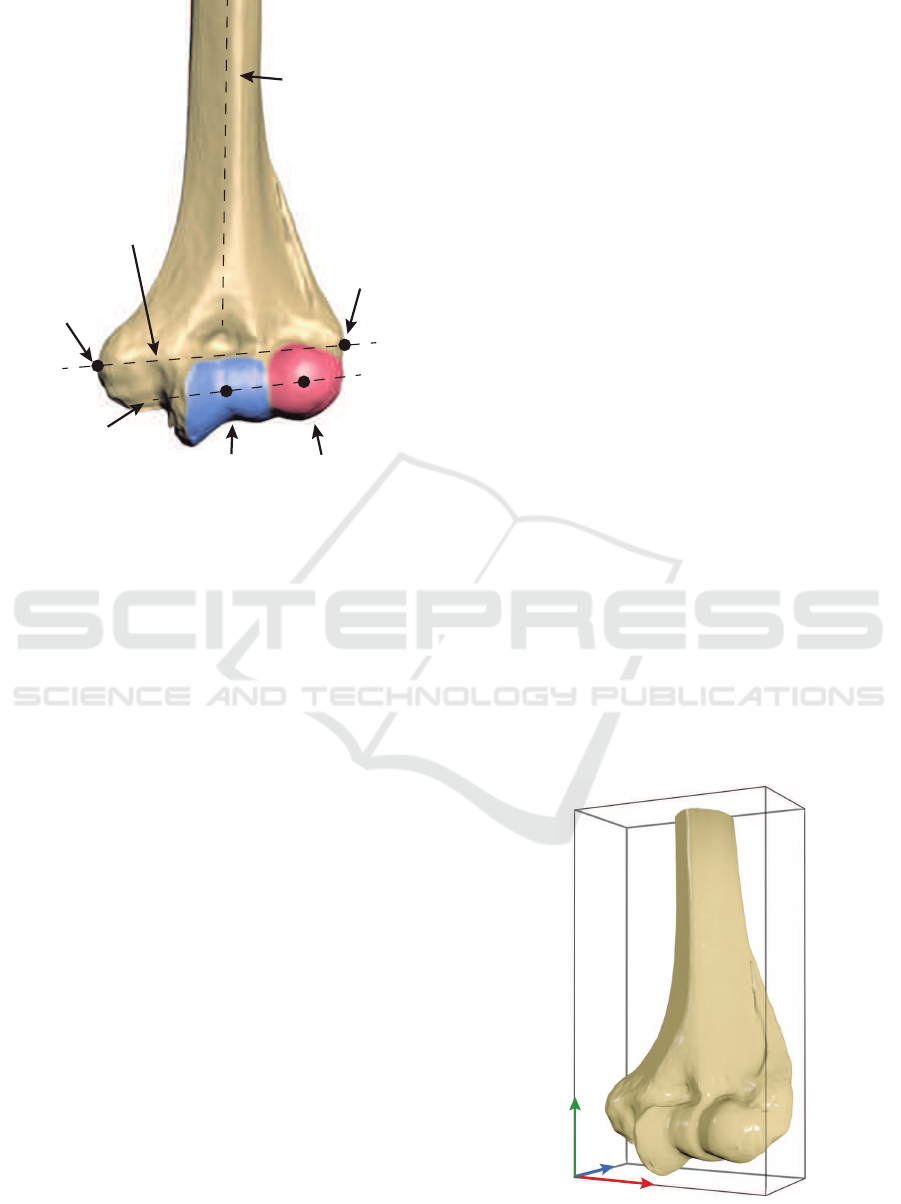
CapitulumTrochlea
Lateral
Epicondyle
Medial
Epicondyle
Humeral
Shaft Axis
(HSA)
Epicondylar
Axis (ECA)
Flexion-Extension
Axis (FEA)
Figure 1: A visual representation of the most representative
landmarks in a healthy distal humerus.
decomposition can be used to efficiently detect
landmarks in specific bones. Subburaj et al.
(2009) detect tibial features by curvature and spatial
adjacency assessment. McDonald et al. (2009)
determined a set of features in humerus to underpin
an adequate alignment of the elbow joint. However,
they provide insufficient technical details about how
landmarks were obtained.
3 ANATOMY OF THE DISTAL
HUMERUS
The humerus is a bone situated in the arm that
connects shoulder and elbow. It is divided into three
parts. The humeral head is the rounded upper region
that allocates the shoulder. A long, cylindrical body
determines the arm direction. The most distal part
determines the elbow joint, that is composed of the
humeroulnar and humeroradial joints. They allow the
arm to be extended from 0 to 180
o
in a healthy person
(Delgado Mart
´
ınez, 2015).
Distal humeral width is commonly defined as
the distance between medial and lateral epicondyles
(also known as epicondylar distance). Finally, the
lowest part of the humerus contains several hollows,
adapting it to ulna and radius. Figure 1 shows several
points of interest: trochlea, capitulum, coronoid
and olecranon. We refer the reader to An (2018);
Shiba et al. (1988); London (1981) for further details
regarding anatomy and biomechanical behavior of the
elbow.
Apart from the referred anatomical features,
several geometric landmarks can be established in
order to improve diagnosis and to compare between
other humeri. According to McDonald et al. (2009),
humeral shaft axis (HSA) is defined as a line along
the humerus, representing the geometric centers of
distal and proximal endosteal canals. Epicondylar
axis (ECA) is also designated as the line through
medial and lateral epicondyles. An orthonormal
reference coordinate system is defined with them,
being the direction of HSA as up vector. The cross
product of HSA and ECA represent f ront and up ×
f ront determines the right orientation of the humerus.
Note that right is the re-orthonormalization of ECA.
Finally, the flexion-extension axis (FEA) is calculated
to represent the direction of the elbow joint.
4 DETECTION OF LANDMARKS
Automatic detection of features is critical to
significantly save processing time. Thus, manual
placement becomes unnecessary to correctly situate
the landmarks.
Our technique recognizes anatomical landmarks
by using a geometric approach with spatial
decomposition. Initially, a triangle mesh is generated
from CT images using a classical Marching cubes
algorithm (Lorensen and Cline, 1987). Afterwards
the resulting mesh is simplified to reduce geometry
x
z
y
Figure 2: Reference coordinate axes of a humerus with its
oriented bounding box.
Automatic Detection of Distal Humerus Features: First Steps
355
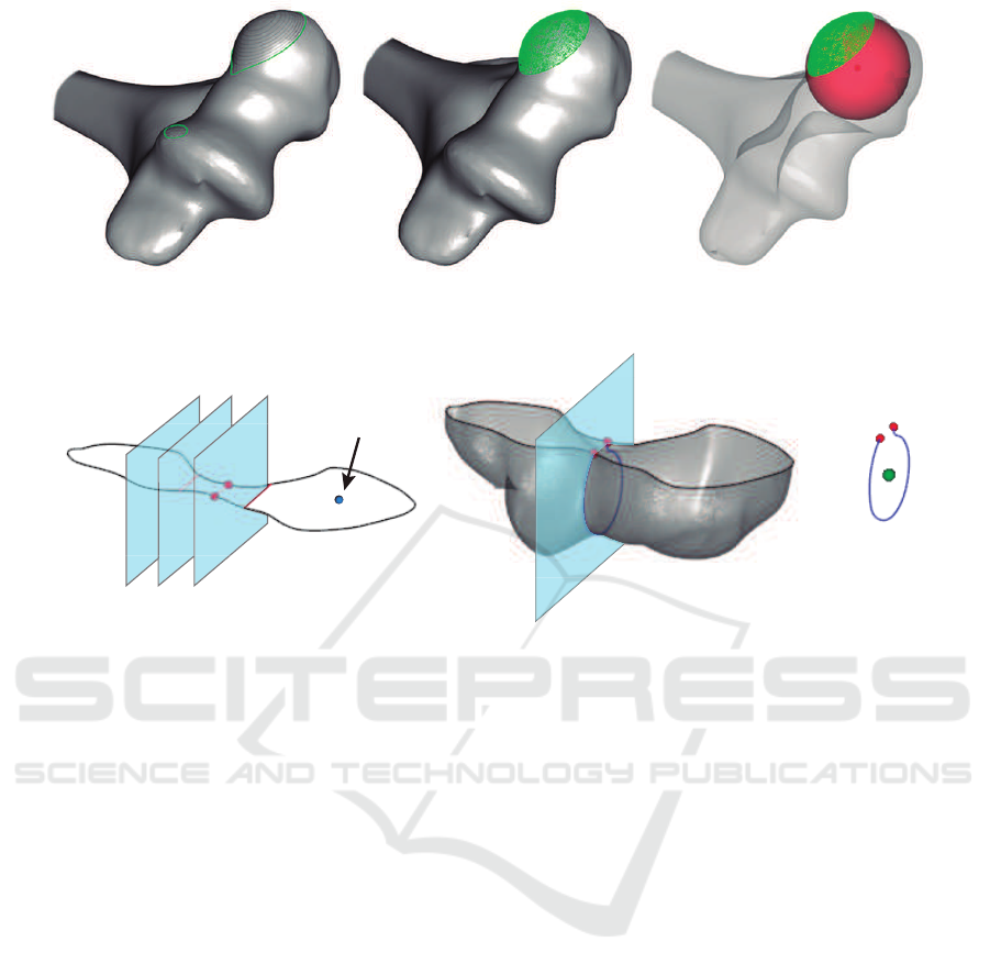
a b c
Figure 3: Steps to detect the center of a capitulum: (a) iterative cutting, (b) point cloud of the spherical cap, (c) approximated
sphere (bone opacity is reduced to improve visualization).
a b c
Capitulum center
Figure 4: Steps to detect the center of the trochlea: (a) an iterative cutting of a slice containing the capitulum center, (b) new
cutting plane through local minimum of the medial zone, (c) approximated circle center.
using a decimation filter. In addition, a Laplacian
smoothing filter is applied in order to reduce
irregularities of the resulting mesh due to the noise of
initial medical images.
A detection of the initial orientation is necessary
to explore the spatial structure of the bone. By
employing a geometrical approach, we consider the
direction of a humerus as the longest side of its
oriented bounding box (OBB). In this manner, the
middle-sized edge corresponds to width, and the
shortest, to depth of the 3D model. Geometric
operations are performed using the OBB edge
directions as a reference coordinate system. Then,
x, y, z vectors define the orientation of the bone (see
Figure 2).
As mentioned before, humeral shaft axis
represents a line along the proximal endosteal canal
of the humerus. This axis is obtained by intersecting
the upper humerus to a set of manually determined
planes parallel to the bottom of the OBB. Finally,
HSA is defined as a linear approximation of the mass
centers of each slice, applying three-dimensional
orthogonal regression (Schneider and Eberly, 2003).
Medial and lateral epicondyles are computed
as tangent points of both flanking planes of the
OBB, i.e., those parallel to the yz face as it is
shown in Figure 2. However, the use of irregular
meshes provoked by low-quality medical images
may cause unpredictable behaviour and void results.
Epsilon-based operations overcome this problem by
adding an inner offset to the original planes. Finally,
epicondylar axis is defined by connecting both
detected points.
The calculation of HSA and ECA is thus resolved
as it has been commented previously. However,
detection of other regions of interest is not fully
concluded in an automated way. McDonald et al.
(2009) also studied the detection of capitulum and
trochlea by using sphere and circle fit, respectively,
in predefined areas. They do not provide sufficient
details about the method for establishing the zones.
Accordingly, in this work in progress, we identified
without any kind of interaction the centers of trochlea
and capitulum, by splitting distal humerus with a set
of planes.
Anatomy of distal humerus shows the capitulum
as a sphere at the end of the bone (Kawanishi et al.,
2013). An iterative cutting is required to find a
spherical cap. The process is stopped when two
polygons are encountered at least. The mesh above
the plane represents a point cloud in where a sphere
can be fitted using a least squares method (Eberly,
2000). As a result, the origin of the sphere is an
accurate approximation of the capitulum center, as it
GRAPP 2019 - 14th International Conference on Computer Graphics Theory and Applications
356

Figure 5: Landmarks detected in four humeri. Results are visually accurate.
is shown in Figure 3.
Trochlear sulcus is centered in distal humerus,
next to the capitulum. It contains a groove to adapt
the humerus to both ulna and radius. The center
of the trochlea is placed approximately at the same
height as the center of the capitulum. Thus, a
cutting plane containing it, parallel to the bottom
of the OBB, is defined. The clip function results a
polygon representing the contour of the slice (Figure
4.a). Due to the trochlear and olecranon sulcus, a
narrowing zone contains the center of the trochlea.
The desired zone can be detected by minimizing the
medial section of this polygon. Finally, an orthogonal
plane to this minimum section is defined to slice the
most distal part of the humerus (Figure 4.b). The
least squares circle fitting algorithm (Eberly, 2000) is
applied to the resulting strip to detect the requested
point (see Figure 4.c).
To conclude, the flexion-extension axis (FEA) is
defined by the connection of trochlea and capitulum
centers.
5 EXPERIMENTS AND RESULTS
This section details the experiments performed to
determine the validity of our method.
A set of four phantom humeri were scanned using
a structured light 3D scanner Artec Eva
1
. Distal
part of each one was registered and 3D meshes were
generated using Artec Studio Professional software.
A program based on The Visualization Toolkit,
VTK (Schroeder et al., 2006) was used to implement
and test our algorithm. Currently, we calculated the
following points of interest for each bone:
• Trochlea center.
1
https://www.artec3d.com/portable-3d-scanners/artec-eva
• Capitulum center.
• Lateral epicondyle.
• Medial epicondyle.
• Humeral shaft axis.
• Epicondylar axis.
• Flexion-extension axis.
Currently, results are visually satisfactory (Figure 5),
as they match with human atlas of anatomy (Rohen
et al., 2011). Further testing is required to compare
between results and ensure a robust algorithm in
different situations.
5.1 Current Issues
As mentioned in Section 4, a correct initial orientation
of the bone is critical to properly apply a spatial
decomposition.
VTK constructs an OBB using a classical
approach (Gottschalk et al., 1996). Mean of the
vertices and a covariance matrix are calculated.
Then, three eigenvectors define the bounding box
edges. Nevertheless, they depend on initial geometry
and orientation of the mesh, producing invalid
results for our algorithm in some cases. In other
words, the reference corner of the OBB is placed
differently depending on models used. When an
initial orientation and a corner are predefined, our
algorithm runs as expected.
6 CONCLUSIONS
We have described an automatic feature detection
algorithm for distal humeri from surface models. This
approach can be applied to detect some anomalies
in a bone or treat pathologies. Our technique has
Automatic Detection of Distal Humerus Features: First Steps
357

been based on a geometrical approach, using a spatial
decomposition. We have accomplished our primary
objective of obtaining bone landmarks in an efficient
way, requesting no interaction. In this position, main
issues of our algorithm have been also analyzed.
Preliminary experiments show promising results in
terms of accuracy and performance.
Currently, we are improving the robustness of the
algorithm, solving mentioned problems in Section
5.1. For instance, current manual parameters
should be dynamically established for each case.
Further testing using additional models is required
to obtain more detailed results (e.g., accuracy and
CPU/memory usage).
ACKNOWLEDGEMENTS
Authors are part of Graphics and Geomatics Group
of Ja
´
en (TIC-144). This research was supported
by the Spanish Ministry of Education, Culture and
Sports via a doctoral grant to the first author (Ref.
FPU16/01439) and partially by Spanish Ministry of
Science, Innovation and Universities through research
projects DPI2015-65123-R and TIN2017-84968-R.
REFERENCES
An, K.-N. (2018). Biomechanics of the Elbow. Morrey’s
the Elbow and its Disorders, pages 33–46.
Baek, S.-Y., Wang, J.-H., Song, I., Lee, K., Lee, J., and
Koo, S. (2013). Automated bone landmarks prediction
on the femur using anatomical deformation technique.
Computer-Aided Design, 45(2):505–510.
Barbu, A., Suehling, M., Xu, X., Liu, D., Zhou, S. K.,
and Comaniciu, D. (2010). Automatic Detection
and Segmentation of Axillary Lymph Nodes. In
Proceedings of the 13th International Conference on
Medical Image Computing and Computer-assisted
Intervention: Part I, MICCAI’10, pages 28–36,
Berlin, Heidelberg. Springer-Verlag.
Brownhill, J. R., Furukawa, K., Faber, K. J., Johnson, J. A.,
and King, G. J. (2006). Surgeon accuracy in the
selection of the flexion-extension axis of the elbow:
An in vitro study. Journal of Shoulder and Elbow
Surgery, 15(4):451 – 456.
Brownhill, J. R., King, G. J., and Johnson, J. A.
(2007). Morphologic analysis of the distal humerus
with special interest in elbow implant sizing and
alignment. Journal of Shoulder and Elbow Surgery,
16(3):S126–S132.
Delgado Mart
´
ınez, A. (2015). Cirug
´
ıa Ortop
´
edica y
Traumatolog
´
ıa. Editorial M
´
edica Paramericana.
Eberly, D. H. (2000). 3D Game Engine Design: A Practical
Approach to Real-time Computer Graphics. Morgan
Kaufmann Publishers Inc., San Francisco, CA, USA.
Gottschalk, S., Lin, M. C., and Manocha, D. (1996).
OBBTree: A hierarchical structure for rapid
interference detection. In Anon, editor, Proceedings
of the ACM SIGGRAPH Conference on Computer
Graphics, pages 171–180.
Han, D., Gao, Y., Wu, G., Yap, P.-T., and Shen, D.
(2015). Robust anatomical landmark detection
with application to MR brain image registration.
Computerized Medical Imaging and Graphics,
46:277–290.
Kawanishi, Y., Miyake, J., Kataoka, T., Omori, S.,
Sugamoto, K., Yoshikawa, H., and Murase, T. (2013).
Does cubitus varus cause morphologic and alignment
changes in the elbow joint? Journal of shoulder and
elbow surgery, 22(7):915–23.
Kim, Y.-C., Chung, Y., and Choe, Y. H. (2017). Automatic
localization of anatomical landmarks in cardiac mr
perfusion using random forests. Biomedical Signal
Processing and Control, 38:370 – 378.
London, J. T. (1981). Kinematics of the elbow. The
Journal of bone and joint surgery. American volume,
63(4):529–35.
Lorensen, W. E. and Cline, H. E. (1987). Marching
cubes: A high resolution 3D surface construction
algorithm. Proceedings of the 14th annual conference
on Computer graphics and interactive techniques -
SIGGRAPH ’87, 21(4):163–169.
McDonald, C. P., Peters, T. M., King, G. J., and
Johnson, J. A. (2009). Computer assisted surgery of
the distal humerus can employ contralateral images
for pre-operative planning, registration, and surgical
intervention. Journal of Shoulder and Elbow Surgery,
18(3):469–477.
Rohen, J. W., Yokochi, C., and L
¨
utjen-Drecoll, E. (2011).
Color Atlas of Anatomy: A Photographic Study of the
Human Body. Wolters Kluwer, Lippincott Williams &
Wilkins, 7 edition.
Ron, O., Joskowicz, L., Milgrom, C., and Simkin,
A. (2002). Computer-based periaxial rotation
measurement for aligning fractured femur fragments
from CT: A feasibility study. Computer Aided
Surgery, 7(6):332–341.
Schneider, P. J. and Eberly, D. H. (2003). Geometric Tools
for Computer Graphics. Elsevier.
Schroeder, W., Martin, K., and Lorensen, B. (2006). The
Visualization Toolkit–An Object-Oriented Approach
To 3D Graphics. Kitware, Inc., fourth edition.
Shiba, R., Sorbie, C., Siu, D. W., Bryant, J. T., Cooke, T.
D. V., and Wevers, H. W. (1988). Geometry of the
humeroulnar joint. Journal of Orthopaedic Research,
6(6):897–906.
Subburaj, K., Ravi, B., and Agarwal, M. (2009).
Automated identification of anatomical landmarks
on 3D bone models reconstructed from CT scan
images. Computerized Medical Imaging and
Graphics, 33(5):359–368.
Vidal, F., Bello, F., Brodlie, K., John, N., Gould, D.,
Phillips, R., and Avis, N. (2006). Principles and
Applications of Computer Graphics in Medicine.
Computer Graphics Forum, 25(1):113–137.
GRAPP 2019 - 14th International Conference on Computer Graphics Theory and Applications
358

Yang, D., Zhang, S., Yan, Z., Tan, C., Li, K., and Metaxas,
D. (2015). Automated anatomical landmark detection
ondistal femur surface using convolutional neural
network. In 2015 IEEE 12th International Symposium
on Biomedical Imaging (ISBI), pages 17–21. IEEE.
Yefeng Zheng, John, M., Rui Liao, Nottling, A.,
Boese, J., Kempfert, J., Walther, T., Brockmann,
G., and Comaniciu, D. (2012). Automatic
Aorta Segmentation and Valve Landmark Detection
in C-Arm CT for Transcatheter Aortic Valve
Implantation. IEEE Transactions on Medical
Imaging, 31(12):2307–2321.
Automatic Detection of Distal Humerus Features: First Steps
359
