Maneuver-based Adaptive Safety Zone for Infrastructure-Supported
Automated Valet Parking
Valerij Schönemann
1
, Mara Duschek
2
and Hermann Winner
1
1
Institute of Automotive Engineering, TU Darmstadt, Otto-Berndt-Straße 2, Darmstadt, Germany
2
Computational Engineering, TU Darmstadt, Dolivostraße 15, Darmstadt, Germany
Keywords: Valet Parking, Safety Zone, Automated Driving, Infrastructure.
Abstract: One of the major challenges for the release of fully automated driving is the design of safe vehicle automation
systems. This work presents a structure to determine a maneuver-specific and adaptive safety zone for
collision avoidance. For this, the overall automated driving system is split into functional scenarios that occur
during the driving task in the operational design domain. Maneuvers are derived from the given scenarios and
car park layouts. Minimum safety distances are determined by injecting worst-case parameters into derived
maneuvers. The superposition of these safety distances leads to a new term: the safety zone. The safety zone
adapts its size according to the performed maneuver as well as the dynamic driving parameters of the engaged
traffic participants such as velocities, timing constraints and deceleration capabilities. The methodology is
applied on the example of cooperative automated valet parking (AVP).
1 INTRODUCTION
The Non-Traffic Surveillance (NTS) data indicate
that from 2012 to 2014 around 5,700 people were
killed and 277,000 were injured in non-traffic crashes
in the US (Singh, 2016). According to the National
Highway Traffic Safety Administration (NHTSA)
non-traffic crashes are classified as single-vehicle
crashes on private roads, two-vehicle crashes in
parking facilities, or collisions with pedestrians in
driveways. Thereby, an average of 42% of the
nonoccupants such as pedestrians and bicyclists were
killed by a forward moving vehicle, 35% by a backing
vehicle, 19% due to a rollaway and 94% of occupant
fatalities occurred in single-vehicle crashes.
New safety issues have to be targeted due to the
design of fully automated vehicles in the upcoming
future. The challenges lie in the release of safe
automated driving systems. A major problem is the
test coverage of the rapidly expanding parameter
space to approve the safety of the automated system
(Wachenfeld and Winner, 2016).
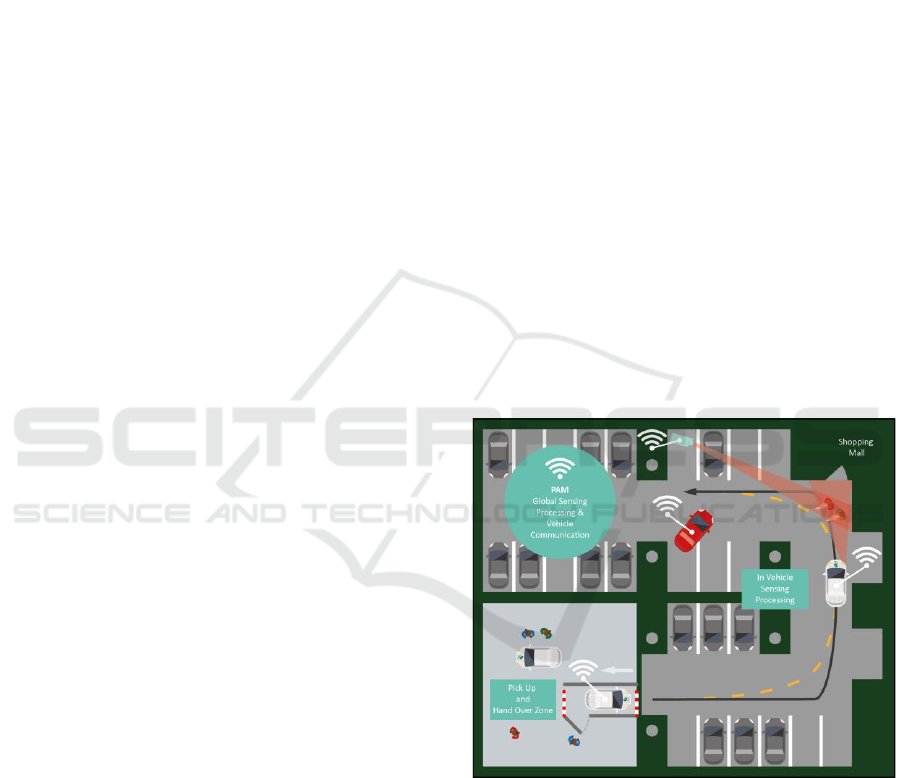
As indicated in Figure 1 automated valet parking
(AVP) provides the service of an autonomous parking
procedure starting at the entrance of a parking facility.
The responsibility of the driving task is shared
between the parking area management (PAM) system
Figure 1: Cooperation between parking area management
(PAM) and automated vehicle to provide an automated
valet parking (AVP) service. Manually driven, driverless
vehicles and pedestrians are present in the parking garage.
(Schönemann, 2018).
and the automated vehicle. The AVP service is
executed driverless and is classified as level 4 of SAE
International’s taxonomy of driving automation. The
authors assume the following pre-conditions for
AVP:
Schönemann, V., Duschek, M. and Winner, H.
Maneuver-based Adaptive Safety Zone for Infrastructure-Supported Automated Valet Parking.
DOI: 10.5220/0007689503430351
In Proceedings of the 5th International Conference on Vehicle Technology and Intelligent Transport Systems (VEHITS 2019), pages 343-351
ISBN: 978-989-758-374-2
Copyright
c
2019 by SCITEPRESS – Science and Technology Publications, Lda. All rights reserved
343
1. Parking management system and automated
vehicle manage the driving task in cooperation.
2. The procedure of handing the automated vehicle
over to and requesting it back from the PAM is
instructed via a terminal (human-machine
interface, HMI).
3. Manually and automatically operated vehicles
are allowed to enter the parking garage.
4. Pedestrians, animals (e.g. dogs), stationary
objects, etc. are present in the car park.
5. Drivers and passengers have to leave the
automated vehicle before AVP is activated.
Today’s automated systems are designed according to
the international standard for functional safety of road
vehicles known as ISO 26262 (ISO, 2011). In
previous work, we applied the design process of the
ISO 26262 on a distributed valet parking system. A
detailed hazard and risk analysis was performed and
corresponding safety requirements were elaborated in
order to provide an as yet uninvestigated safety
concept for valet parking. The safety analysis leads to
the conclusion that parameters such as pose,
dimensions, velocity, existence and the class of
membership have to be known in order to avoid a
potential collision. Figure 2 shows the correlation
between these parameters. According to Dietmayer
(Dietmayer et al., 2016), the following uncertainties
exist:
State uncertainty: Represents the measuring
errors of the object’s dimensions (length, width,
height), the object’s pose and the object’s
velocity.
Existence uncertainty: Uncertainties whether an
object mapped into the representation actually
exists. This concerns mainly false positives and
false negatives.
Class uncertainty: Describes uncertainties in
classifying an object and predicting its behavior.
The classes pedestrians, stationary objects,
vehicles, or other are available. The degree of
granularity depends on the use case.
However, in our previous work we did not yet
investigate in which area these parameters have to be
measured. A maneuver-specific safety zone is
elaborated to avoid collisions with static objects,
pedestrians and automated or manually driven
vehicles.
2 RELATED WORK
Safety is crucial for the commercialization of
automated driving. Safe vehicle automation systems
Figure 2: Uncertainty domains in the environment
perception and parameters which has to be determined for
collision avoidance (the object’s position, orientation,
dimensions, velocity, existence and class of membership).
shall intervene in case of an upcoming accident and
release the driver from this burden. A major challenge
is to design distributed systems which share the
responsibility for the driving task. Fully automated
valet parking is such a distributed system.
Each complex automation system causes the issue
of testing. Up to now, there is no international
standard for approving the safety of an automated
driving system. The ISO 26262 only addresses a
systematic approach for designing functionally safe
electrical and electronic systems of road vehicles.
Neither a standard, nor a methodology is specified to
develop a safety concept specifically for automated
driving systems. However, the safety approval and
new testing methods are required for the release of
automated driving (Winner, 2015).
Reschka et al. (Reschka, 2016) examined various
safety concepts for autonomous driving without
driver monitoring. An automated driving system
requires safety mechanisms to transfer the system into
a safe state. For an AVP system, the authors
introduced a remote operator. An external mechanism
provides the possibility to stop a driverless vehicle in
case of an emergency. This requires a secure and
reliable communication between the vehicle and a
remote control station. Furthermore, the authors
surveyed safety concepts in other domains. Safety
mechanisms for railway are integrated into the
infrastructure: a monitoring system prevents a train to
enter a track that is already occupied. The stopping
distances for railway are relatively large compared to
vehicles and the complexity of scenarios is lower due
to the control mainly in longitudinal direction.
OR
Sense-failure
State variables Existence
Class of
Membership
OR
Pose Dimensions Velocity
??
VEHITS 2019 - 5th International Conference on Vehicle Technology and Intelligent Transport Systems
344
Chellaswamy et al. (Chellaswamy, 2015)
introduces a system to identify crowded areas to
avoid collisions. The authors state that most accidents
occur in dense traffic areas. The system adapts the
vehicle velocity at various safety zones. Once a
vehicle enters a dense traffic area, a controller
automatically reduces the vehicle velocity. The
described safety zone is not realized vehicle-specific
but area-specific. The methodology reduces the
severity of accidents for traffic participants, but
automated driving at lower velocities becomes more
time consuming.
Bosch and Daimler (Automotive World, 2018)
recently developed a prototype for a cooperative valet
parking system. The driving task is shared between
vehicles and intelligent infrastructure during mixed
traffic. Manually driven and automated vehicles as
well as pedestrians are present in the parking garage.
Environment perception and trajectory planning is
performed by the parking area management system
whereas the lateral and longitudinal actions are
executed by the vehicle. The prototype marks the first
pilot of its kind. However, further information
concerning the safety concept is not provided.
Schwesinger et al. (Schwesinger, 2016) and Löper
et al. (Löper, 2013) focus on a functional
development of a valet parking prototype capable of
performing fully automated navigation, but a
specification of a safety relevant space is not part of
the investigation.
The state of the art reveals that a safety concept
for automated valet parking is missing. Areas of
interest for safety considerations are not yet addressed
for AVP. However, a definition of an area, in which
the perception of objects for collision avoidance is
mandatory, has to be given. Outside of this area the
perception of objects is not required. The magnitude
of this area is maneuver-specific and therefore an
investigation of occurring maneuvers in a parking
garage is required. Additionally, a specification for
the infrastructure support has to be given for a
cooperative valet parking service.
This work aims to specify areas of interest around
the ego-vehicle in which the traffic participant’s
parameters have to be determined for collision
avoidance. The safety zone provides a description of
the relevant space in the environment perception task
that is executed by the parking area management
system and the automated vehicle. The results of this
work can be used to increase the safety performance
of the overall system and optimize the system
accordingly.
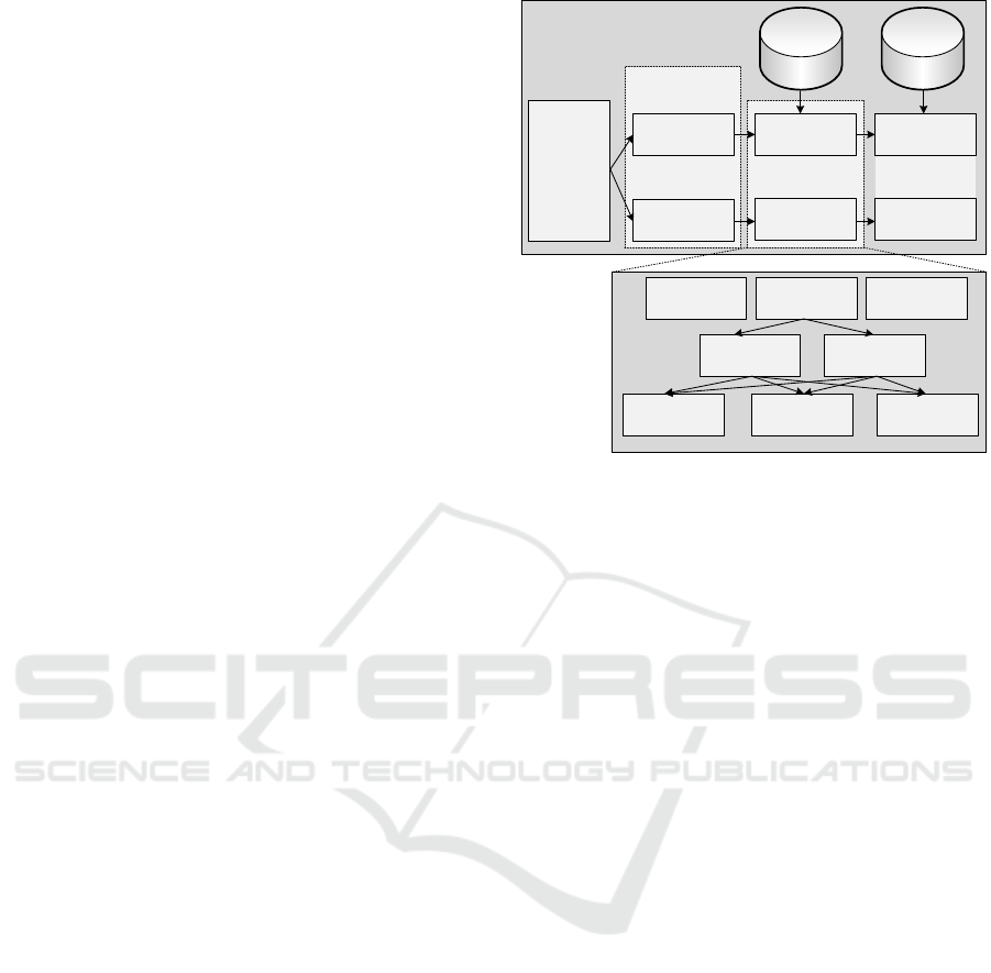
Figure 3: Decomposition of the automated driving system
in functional scenarios and investigation of possible
maneuvers for each scenario. The classification, and the
moving behavior as well as worst-case constraints ensure
the calculation of required safety distances for collision
avoidance.
3 METHODOLOGY
As illustrated in Figure 3 the overall valet parking
system is split into functional scenarios that occur
during the execution of the valet parking procedure.
According to Ulbrich et al. (Ulbrich, 2015) a scenario
describes snapshots of the environment and the
interaction of entities while time is progressing.
Thereby, 6 major scenarios can be investigated:
vehicle handover to parking area management
system, automated driving to a point of interest,
automated maneuvering into the parking space,
automated leaving of the parking space, vehicle
handover to driver and aborting the valet parking
procedure. These scenarios are further described in
the following section.
Each scenario is examined according to specific
maneuvers that are instructed by the automation
system. Maneuvers are extracted from layouts of car
parks (Pech, 2009). The determination of the safety
distances depends on the object’s class which ideally
is known. If the class type equals a vehicle, it can be
distinguished whether the potential collision partner
is manually driven or driverless. This kind of
information could be provided by the parking area
management system or C2C. If the vehicle is operated
driverless, it was registered by the PAM during the
handover and tracked. If no object information is
.
.
.
Automated
Driving
System
Maneuver 1
Maneuver X
.
.
.
Adaptive
Safety Zone 1
Adaptive
Safety Zone X
Moving
Towards
Moving Away
Manually
Driven
Automated
Other
Obstacle
VehiclePedestrian
Worst Case
Constraints
Car Park
Layouts
.
.
.
Scenario 1
Scenario X
Decomposition
in Scenarios
Maneuver-based Adaptive Safety Zone for Infrastructure-Supported Automated Valet Parking
345

provided, it should be assumed that the potential
collision partner is a manually driven vehicle. The
assumption is valid since compared to an automated
vehicle, more conservative parameters will be
assigned to the collision partner. Even if the
assumption is false, a sufficient safety distance is still
provided. Furthermore, the moving behavior of the
potential collision partner can be examined in order
to check whether the object is moving towards the
ego-vehicle, moving away or neither moving away
nor moving towards.
Worst case constraints such as timing, maximum
allowed velocity and minimum required deceleration
are defined for the operational domain and serve as an
input for each maneuver to specify a minimum
required safety distance for collision avoidance. The
safety zone adapts its size parameter-dependent at
each time step.
4 DECOMPOSITION OF
SCENARIOS
In the previous work, the valet parking system was
decomposed into functional scenarios that occur
during operation. These scenarios are illustrated in
Figure 4 and are used in combination with layouts of
car parks to identify executed maneuvers within
AVP.
A. Vehicle Handover to Parking Area Management
System
The valet parking procedure starts with the drop-off
of the automated vehicle at the handover zone. The
system checks whether the vehicle is located in the
handover zone, is in standstill and, correctly oriented
and, whether all doors are closed and all persons have
left the handover zone. The PAM may transmit a
static map of the parking garage and a predefined
trajectory to the corresponding parking spot. After the
parking request is instructed, the vehicle is handed
over to the parking area management and the
automation takes over the responsibility for the
further steps of the driving task. The handover is
successful if the specified constraints are met and a
parking spot can be assigned.
B. Automated Driving to a Point of Interest
If the handover is successful, the system has to
navigate the vehicle to the point of interest. The point
of interest is defined as the desired location which
mainly includes the assigned parking spot, the pick-
up zone or the location after an emergency brake and
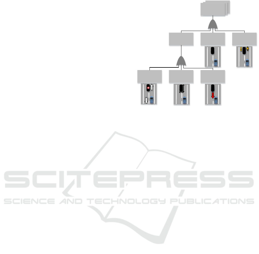
Figure 4: Scenarios which occur during automated valet
parking: (a) vehicle handover to parking area management
system and vehicle handover to driver after a handback
request, (b) automated driving to a point of interest such as
the parking spot or the exit, (c) automated maneuvering into
and automated leaving of the parking space.
full stop. Thereby, the system shall ensure that the
vehicle stays in the statically defined drivable area.
The environment is perceived via radar, lidar and
ultrasonic sensors. Several maneuvers have to be
accomplished: following the straight or curved lane,
turning left/right, crossing of an intersection and
driving on a ramp. The end state is reached if the
vehicle arrives at the desired point of interest without
colliding. This scenario does not include the
maneuvering into the parking space.
C. Automated Maneuvering into the Parking Space
When the automated vehicle arrives nearby the
parking spot, the parking maneuver can be executed.
Either the PAM has already checked the required free
parking space and/ or the vehicle takes over the
analysis of the parking spot to decide whether the
parking space is appropriate for parking. Thereafter,
longitudinal or lateral actions have to be executed to
place the vehicle properly. The maneuver driving
backwards is part of the scenario. The vehicle may
park forward or reverse. The parking spots are
arranged from 0° to 90° with respect to the lane.
However, reverse parking is recommended in order to
reduce the required range of the rear side sensors
when leaving the parking spot in reverse. The sensor
range requirements can then be shifted to the vehicle
front since the sensor range is already required for
intersection crossings. The end state is successfully
reached if the assigned parking spot is arrived
collision-free, the vehicle size does not exceed the
parking spot, the parking brake is set and the vehicle
is on standby.
D. Automated Leaving of the Parking Space
If the driver initiates a handback request, the
automated vehicle is triggered to leave the parking
space. The required trajectory to the pick-up zone is
either computed by the ego-vehicle or received from
Pick-up
Zone
Parking
Spot
(a) (b) (c)
Handover
Zone
VEHITS 2019 - 5th International Conference on Vehicle Technology and Intelligent Transport Systems
346

the PAM. Maneuvering out of the parking spot is
possible in forward and reverse direction. However,
as already stated in scenario C, forward leaving is
recommended. The maneuvers accelerate/ decelerate,
maneuvering out of the parking spot, and driving
backwards are required. The execution is successful
if no traffic participant is harmed and the automated
vehicle left the parking spot until the maneuver
‘following the straight or curved lane’ from scenario
B can be performed.
E. Vehicle Handover to Driver
When the vehicle arrives at the exit of the parking
garage, the vehicle will be placed at the pick-up zone,
the parking brake has to be set, the vehicle engine has
to be turned off, and the valet parking function needs
to be deactivated. If the constraints are met and no
traffic participant is harmed, the scenario is
considered to be successful.
F. Aborting the Valet Parking Procedure
This scenario describes the abort of the valet parking
service, which is equivalent to an early initiated
handback request. The automated vehicle does not
drive to the assigned parking spot but instead directly
to the exit of the parking garage. Therefore, scenario
B and E still have to be executed. Once the vehicle is
located in the pick-up zone in standstill, the valet
parking procedure can be deactivated and the driver
is able to enter the vehicle.
5 EXAMINATION OF
MANEUVERS
The scenarios A - F serve as an input to derive
maneuvers for AVP. A stopping distance is required
for each maneuver in order to avoid a collision with
traffic participants. The superposition of these
maneuver-specific stopping distances leads to the
introduction of a new term: the safety zone. The safety
zone adapts its distances according to the performed
maneuver as well as dynamic driving parameters of
the engaged traffic participants such as velocities,
timing constraints and deceleration capabilities. The
following maneuvers were found:
Following a straight or curved lane: This
maneuver includes the primitives accelerate and
decelerate for longitudinal control as well as lane
keeping/ steering for lateral control. The ego-
vehicle’s position is thereby kept at the lane
center.
Driving backwards: This maneuver is executed
during the maneuvering into the parking spot.
Thereby, reverse parking is recommended in
order to reduce the system’s perception
requirements to the rear side.
Turning left/right: A turn is required at
intersection crossings and when leaving the
parking space to the left or to the right for parking
spaces oriented in lateral direction.
Crossing an intersection: If the vehicle arrives at
an intersection, turning left, turning right or
crossing the intersection is possible. The
maneuver addresses the crossing.
Coverage during maneuvers: Coverage of
objects by other traffic participants or by parking
construction causes undetected objects inside the
ego-vehicle’s safety zone without the vehicle’s
knowledge.
6 WORST-CASE CONSTRAINTS
Before the safety distances are determined
systematically, the defined constraints used here
should be mentioned. These assumptions serve as
constraints to calculate the stopping distances. Once
worst-case safety distances are determined, they are
also valid for less critical situations and should avoid
collisions. Thereby, the parameters are defined as
velocity , system response time
from the
plausibility check until the initiation of the brakes,
driver reaction time
, response time of the brakes
, time delay of the brake until buildup of
deceleration
, a minimum guaranteed deceleration
given by the friction coefficient
and gravity constant . In a parking garage, the
authors assume a maximum allowed forward velocity
of
, a velocity in reverse
and a maximum
allowed velocity at intersections
. Additionally,
a safety margin
is required to prevent a collision.
These rather conservative considerations are valid for
the operational design domain and are summarized in
Table 1.
7 DERIVATION OF AN
ADAPTIVE SAFETY ZONE
Based on the found maneuvers and worst case
constraints an adaptive safety zone is derived. As
described in the methodology it is necessary to
Maneuver-based Adaptive Safety Zone for Infrastructure-Supported Automated Valet Parking
347
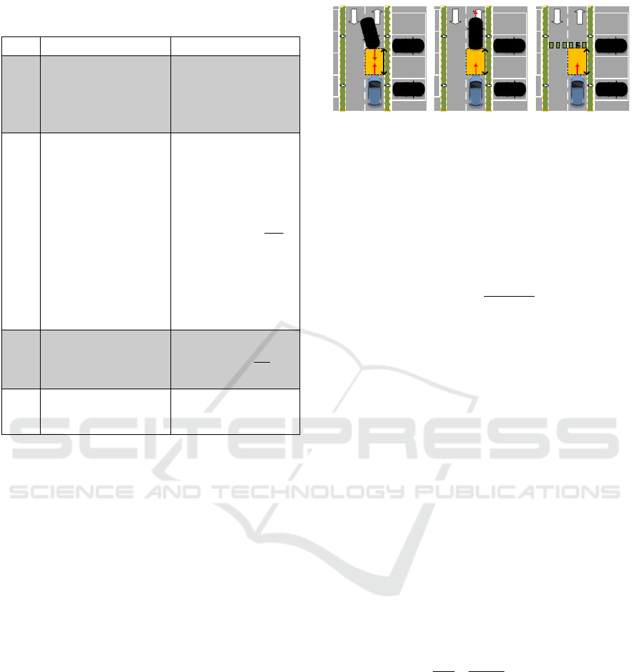
Table 1: Pre-defined Constraints for Automated Valet
Parking.
ID
Description
Value
C01
Maximum allowed
velocities: in forward
, in reverse
, at intersections
C02
Worst-case expected
time delays: system
response time from
the plausibility check
until initiating the
brakes
, driver
reaction time
,
lag time of the brake
given by the
response time of the
brake
and the
time until buildup of
deceleration
0.3 s
1.5 s
1
C03
Minimum expected
deceleration
for object-
and ego-vehicle
C04
Safety margin
1) Breuer and Bill, 2008
distinguish between several cases which will be
explored for each maneuver in the following.
A. Following a Straight or Curved Lane
When the ego-vehicle follows the lane there are three
cases regarding the stopping distances as shown in
Figure 5:
Case (A,a): The detected object is moving
towards the ego-vehicle. In this case, it is useful
to distinguish between two possibilities: A
collision of two vehicles and either both vehicles
are braking (A,a1) or only the automated vehicle
is braking (A,a2).
Case (A,b): The object is moving away and
Case (A,c): The object is neither moving towards
the ego-vehicle nor moving away.
For each of these cases different stopping distances
have to be considered. In case (A,a1), it is assumed
that both vehicles react at the same time. The object
vehicle can either be manually driven or driverless.
Thus, the worst case object’s reaction time
has
to be taken into account. The overall required
Figure 5: Safety zone (yellow) for following a straight or
curved lane: (a) object is moving towards the ego-vehicle,
(b) object is moving away and
, (c) object is
neither moving away nor moving towards.
stopping distance is given by the overlap of the single
stopping distances calculated by
(1)
Equation (1) produces the maximum spanned safety
zone for the worst-case
. This
can be seen as the minimum required perception
range
to the front for AVP. Once the object is
measured in this area, the safety zone adapts its size
according to the object’s velocity and reaction
capability as presented in Figure 5.
For the manually driven vehicle the driver’s reaction
time has to be injected into the formula by
, whereas for an automated vehicle as a collision
partner the equation simplifies by setting
.
The case (A,a2) occurs if the automated vehicle has
to be in standstill for collision avoidance and only the
control of the automated vehicle is possible. The
required distance
is then given by the stopping
distance of the ego-vehicle and the driven distance of
the manually operated or automated vehicle
(2)
Case (A,b) can be approximated by assuming an
object that is not moving since stopping in front of a
standing object is always more safety critical
compared to objects that are moving away. When
considering this approximation, the object has no
impact on the stopping distance and therefore the
stopping distance is only influenced by the ego-
vehicle’s parameters. This is achieved by setting
in equation (2). The same considerations
can be applied to case (A,c), since case (A,b) is
reduced to case (A,c).
d
req,f3
d
req,f1
d
req,f2
(a) (b) (c)
VEHITS 2019 - 5th International Conference on Vehicle Technology and Intelligent Transport Systems
348
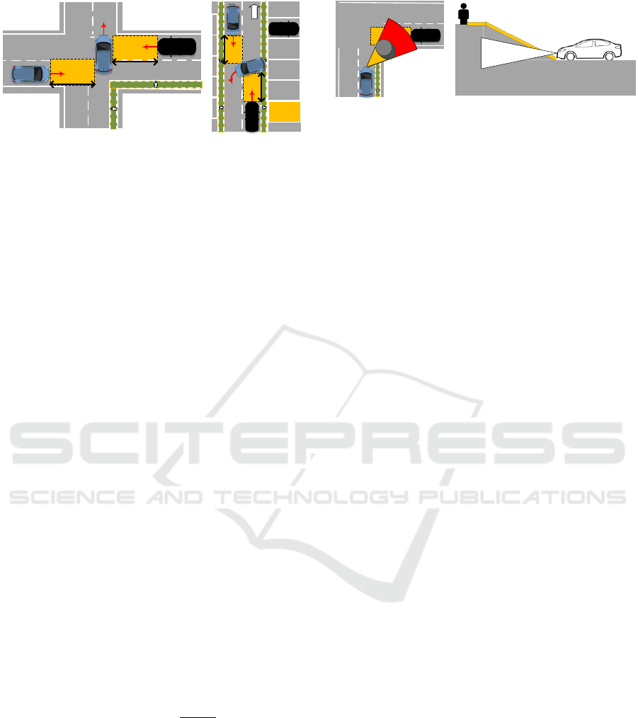
Figure 6: Safety zone (yellow) for intersection crossing
(left) which reveals similar characteristics to leaving the
parking spot (right).
B. Driving Backwards
This maneuver has similar characteristics to the
maneuver following a straight or curved lane.
Similarly, three cases occur while driving in reverse:
Case (B,a): The detected object is moving
towards the ego-vehicle
Case (B,b): The object is moving away and
Case (B,c): The object is neither moving towards
the ego-vehicle nor moving away.
The stopping distances are calculated as described in
the maneuver following a straight or curved lane, but
considering that the ego-vehicle is driving in reverse
and an object is detected to the rear. The minimum
required perception range to the rear for AVP is given
for
,
and
.
Once an object is measured in this area, the safety
zone adapts its size according to the object’s
parameters.
C. Turning Left/ Right:
In case of turning right at an intersection or when
leaving the parking spot as shown in Figure 6, traffic
participants coming from the left need to have at least
a minimum distance
to the ego-vehicle in order
to be able to successfully brake in case of an
emergency. The required distance is dependent on
whether the object-vehicle is manually driven or
driverless.
(3)
For an automated collision partner approaching from
the side with a velocity
, the required safety
distance is given by setting the reaction time
. If no information is provided by the
infrastructure about the type of object, the system
assumes that the object is a manually driven vehicle.
The assumption is valid since rather conservative
parameters are allocated to the traffic participant.
Figure 7: Covered perception area at an intersection (left).
Relevant object which is not in the ego-vehicle’s sensor
view when driving on a ramp (right).
Even if the assumption is false, a sufficient safety
distance is assigned by
.
The minimum required distance that has to be
checked by the ego-vehicle when entering the
corresponding lane is given for
.
D. Crossing an Intersection
This maneuver includes the same safety distances as
described in the maneuver turning left/ right except
that no turn is actually performed by the ego-vehicle.
Same dependencies occur: either the vehicle-type has
to be known or a manually driven vehicle as a worst
case is assumed to provide a sufficient safety
distance.
E. Coverage
The system has to manage potential collisions for
each of the upper described maneuvers even if the
collision partner is covered for the ego-vehicle. The
issue can only be solved by C2I since top mounted
sensors will not be covered by traffic participants or
by parking construction. Therefore, the required
information from safety areas have to be transmitted
to the ego-vehicle. The covered area for the ego-
vehicle has to be determined by the parking area
management system and top-mounted sensors located
in this area have to replace the ego-vehicle’s sensor
view.
The case of driving on a ramp requires the system to
distinguish whether a detected object is a ramp. Here,
similar safety distances as described for following a
straight or curved lane have to be considered just that
the deceleration depends on the slope of the ramp
(4)
These safety distances have to be provided by the
parking area management system as shown in Figure
7.
Derivation of the Overall Safety Zone
The superposition of the derived maneuver-based
stopping distances shows that the overall safety zone
is created by the ego-vehicle’s and the object’s
Parking
Spot
d
req,i2
d
req,i2
d
req,i1
d
req,i1
d
req,ego
PAM
Maneuver-based Adaptive Safety Zone for Infrastructure-Supported Automated Valet Parking
349
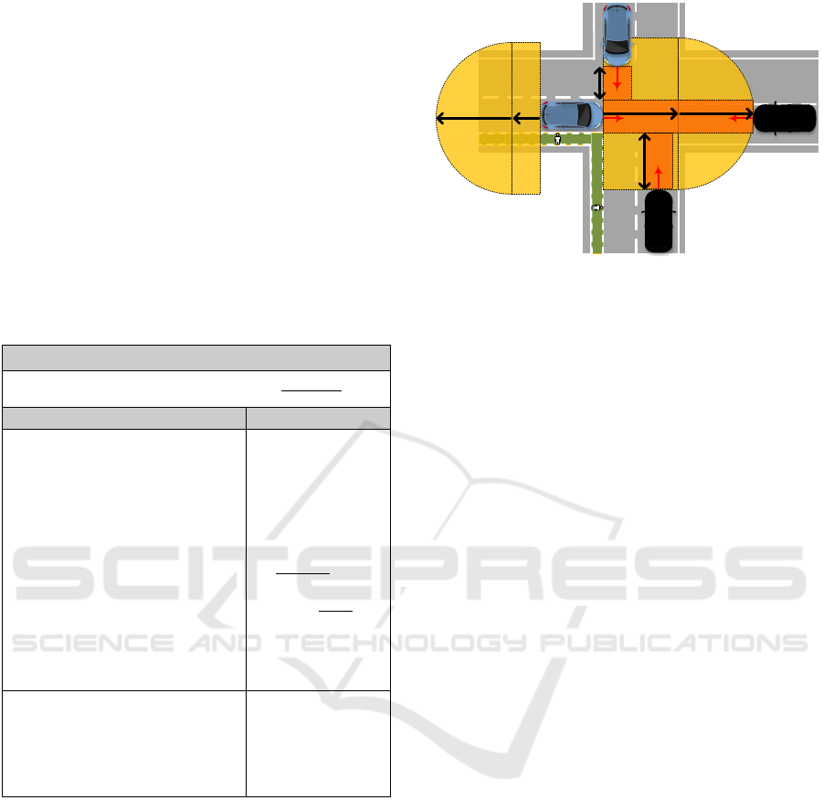
travelled envelopes given by their widths and
stopping distances. A radius with the object’s
stopping distance can be spanned around the ego-
vehicle to the front and to the rear. Furthermore, the
ego-vehicle’s stopping envelope has to be added
when following a straight lane or driving backwards.
Once the object is oriented in a 90° angle to the ego-
vehicle such as at intersections, only the object’s
stopping envelope has to be considered. As a result,
the overall safety zone is given by the ego-vehicle and
the object’s travelled envelope as shown in Figure 8.
The main equation and overall maneuver specific
constraints are listed in Table 2.
Table 2: Main equation and maneuver-specific constraints
for determining the required safety zone.
Main Equation
Maneuvers
Safety Zone
Following a straight or curved
lane
or
Driving backwards
or
Coverage
Case (A/B/E,a1):
Case (A/B/E,a2):
Case (A/B/E,b/c):
Turning left/ right
or
Crossing an intersection
or
Coverage
Case (C/D/E):
8 CONCLUSION
Automated driving has revealed challenges for
functional safety. A safety concept for automated
valet parking was not yet targeted. Furthermore,
mandatory perception areas for collision avoidance
were not yet addressed in the state of the art for AVP.
The shapes of these areas are maneuver-specific and
therefore an examination of occurring maneuvers in a
parking garage was required. For this, the overall
system is decomposed in functional scenarios and
each scenario is investigated for the executed
maneuvers. Worst-case constraints such as timing,
maximum allowed velocity and minimum required
Figure 8: Overall safety zone (yellow) to the front and to
the rear given by the superposition of the ego-vehicle’s and
object’s travelled envelopes and corresponding adaptation
(red) due to the occurrence of moving traffic participants.
deceleration are derived for cooperative valet parking
in a mixed traffic environment. These constraints
served as an input to calculate minimum required
safety distances for each maneuver. The authors
investigated in which areas parameters such as pose,
dimensions, velocity, existence, and the class have to
be known in order to avoid a potential collision for
automated valet parking.
The superposition of these safety areas leads to the
term adaptive safety zone. The safety zone provides a
description of a safety-relevant space for the
environment perception. The collision partner’s
parameters are measured in a minimum required
perception zone. The adaptive safety zone is
determined for each maneuver by distinguishing
between the collision partner’s characteristic and it’s
moving behavior. The parking area management
system provides the safety zone for the automated
vehicle if coverage prevents the perception task or if
safety critical objects do not appear in the vehicle’s
sensor view. The results of this work can be used to
adjust the AVP system requirements for the
environment perception task according the
determined safety zone. The results illustrate which
areas top mounted sensors have to examine to
increase the safety performance of the overall system.
ACKNOWLEDGEMENTS
This work has been conducted within the ENABLE-
S3 project that has received funding from the ECSEL
Joint Undertaking under Grant Agreement no.
692455. This Joint Undertaking receives support
from the European Union’s HORIZON 2020 research
and innovation programme and Austria, Denmark,
Germany, Finland, Czech Republic, Italy, Spain,
d
req,i1
d
req,i2
d
req,obj
d
req,egoF
d
req,egoR
d
req,obj
VEHITS 2019 - 5th International Conference on Vehicle Technology and Intelligent Transport Systems
350

Portugal, Poland, Ireland, Belgium, France,
Netherlands, United Kingdom, Slovakia, Norway.
REFERENCES
Automotive World, 2018. Daimler and Bosch jointly
premiere automated valet parking in China. From:
www.automotiveworld.com/news-releases/daimler-
and-bosch-jointly-premiere-automated-valet-parking-
in-china/. Accessed: November 2018.
Breuer, B., and Bill, K. H. 2008. Brake technology
handbook.
Chellaswamy, C., Rammohan, T., Swarna, Y., Bharathi, R.
R., & Saranya, R, 2015. Development of safety zone
detection and collision avoidance using wireless
network. In Smart Technologies and Management for
Computing, Communication, Controls, Energy and
Materials (ICSTM), 2015 International Conference on
pp. 112-118.
Dietmayer, K., 2016. Predicting of machine perception for
automated driving. In Autonomous Driving: Technical,
Legal and Social Aspects, Maurer, M., Gerdes, J. C.,
Lenz, B. and Winner, H., Eds.: Springer, pp. 407-424.
International Organization for Standardization, 2011. ISO
26262: Road vehicles - Functional Safety. Geneva,
Switzerland.
Löper, C., Brunken, C., Thomaidis, G., Lapoehn, S.,
Fouopi, P. P., Mosebach, H., & Koster, F., 2013.
Automated valet parking as part of an integrated travel
assistance. In 16th International IEEE Conference on
Intelligent Transportation Systems-(ITSC), pp. 2341-
2348.
Pech, A., Warmuth, G., Jens, K., & Zeininger, J., 2009.
Parkhäuser - Garagen: Grundlagen, Planung, Betrieb.
Birkhäuser. pp. 375-410.
Reschka, A., 2016. Safety Concept for Autonomous
Vehicles, In Autonomous Driving – Technical, Legal
and Social Aspects pp. 473–496, Springer Nature.
Singh, S. 2016. Non-traffic surveillance: fatality and injury
statistics in non-traffic crashes 2012 to 2014, No. DOT
HS 812 311.
SAE, 2016. Taxonomy and Definitions for Terms Related
to Driving Automation Systems for On-Road Motor
Vehicles (J3016). Society of Automotive Engineers.
Schönemann, V. and Winner, H. et al., 2018. Scenario-
based Functional Safety for Automated Driving on the
Example of Valet Parking. In IEEE Future Information
and Communication Conference, Singapore.
Schwesinger, U., Bürki, M., Timpner, J., Rottmann, S.,
Wolf, L., Paz, L. M., ... & Heng, L., 2016. Automated
valet parking and charging for e-mobility. In Intelligent
Vehicles Symposium (IV), pp. 157-164.
Ulbrich, S., Menzel, T., Reschka, A., Schuldt, F., Maurer,
M., 2015. Defining and Substantiating the Terms
Scene, Situation, and Scenario for Automated Driving.
In IEEE 18th International Conference on Intelligent
Transportation Systems (ITSC), pp. 982–988.
Wachenfeld, W. and Winner, H. 2016. The Release of
Autonomous Vehicles. In Autonomous Driving:
Technical, Legal and Social Aspects. Maurer, M.,
Gerdes, J. C., Lenz, B., and Winner, H. , Eds.: Springer.
pp. 425–449.
Winner, H., Graupner, M. and Wachenfeldt, W., 2015. How
to Address the Approval Trap for Autonomous
Vehicles (Keynote). In IEEE 18th International
Conference on Intelligent Transportation Systems
(ITSC).
Maneuver-based Adaptive Safety Zone for Infrastructure-Supported Automated Valet Parking
351
