Efficient Recognition and 6D Pose Tracking of Markerless Objects
with RGB-D and Motion Sensors on Mobile Devices
Sheng-Chu Huang
1
, Wei-Lun Huang
1
, Yi-Cheng Lu
1
, Ming-Han Tsai
1
, I-Chen Lin
1
,
Yo-Chung Lau
2
and Hsu-Hang Liu
2
1
College of Computer Science, National Chiao Tung University, Hsinchu City, Taiwan
2
Telecommunication Laboratories, Chunghwa Telecom Co., Ltd, Taoyuan City, Taiwan, Taoyuan City, Taiwan
{lyc0326, hsuhangg}@cht.com.tw
Keywords: Object Recognition, Pose Estimation, Markerless Tracking, Sensors on Mobile Devices.
Abstract: This paper presents a system that can efficiently detect objects and estimate their 6D postures with RGB-D
and motion sensor data on a mobile device. We apply a template-based method to detect the pose of an object,
in which the matching process is accelerated through dimension reduction of the vectorized template matrix.
After getting the initial pose, the proposed system then tracks the detected objects by a modified bidirectional
iterative closest point algorithm. Furthermore, our system checks information from the inertial measurement
unit on a mobile device to alleviate intensive computation for ease of interactive applications.
1 INTRODUCTION
Recently, Augmented Reality (AR) has achieved
significant growth and been applied in various
applications, and a large proportion of these
applications perform on mobile devices. For AR
applications, interacting with real-world objects is an
essential factor, which relies on techniques of object
recognition and tracking. Recognizing and tracking
postures of real objects is one of the main research
topics in computer graphics and vision fields, and
quite a number of emerging methods can perform on
a high-end computer in real time. However, due to the
limited memory and the requirement of low-power
consumption for mobile devices, it is still a challenge
to efficiently perform object recognition and tracking
methods on such a platform.
Popularly used detection and tracking systems for
AR usually have to attach particular markers to the
target surface or rely on specific texture features.
Under this circumstance, a user has to keep markers
visible or the system cannot find the target
successfully. To overcome these limitations, we
developed a novel system that can recognize the
object and analyze its 6D (3D rotations and 3D
translations) postures precisely by using a template-
based method. Then our system tracks the detected
object and updates its pose according to the RGB-D
and motion sensing data acquired by a mobile device.
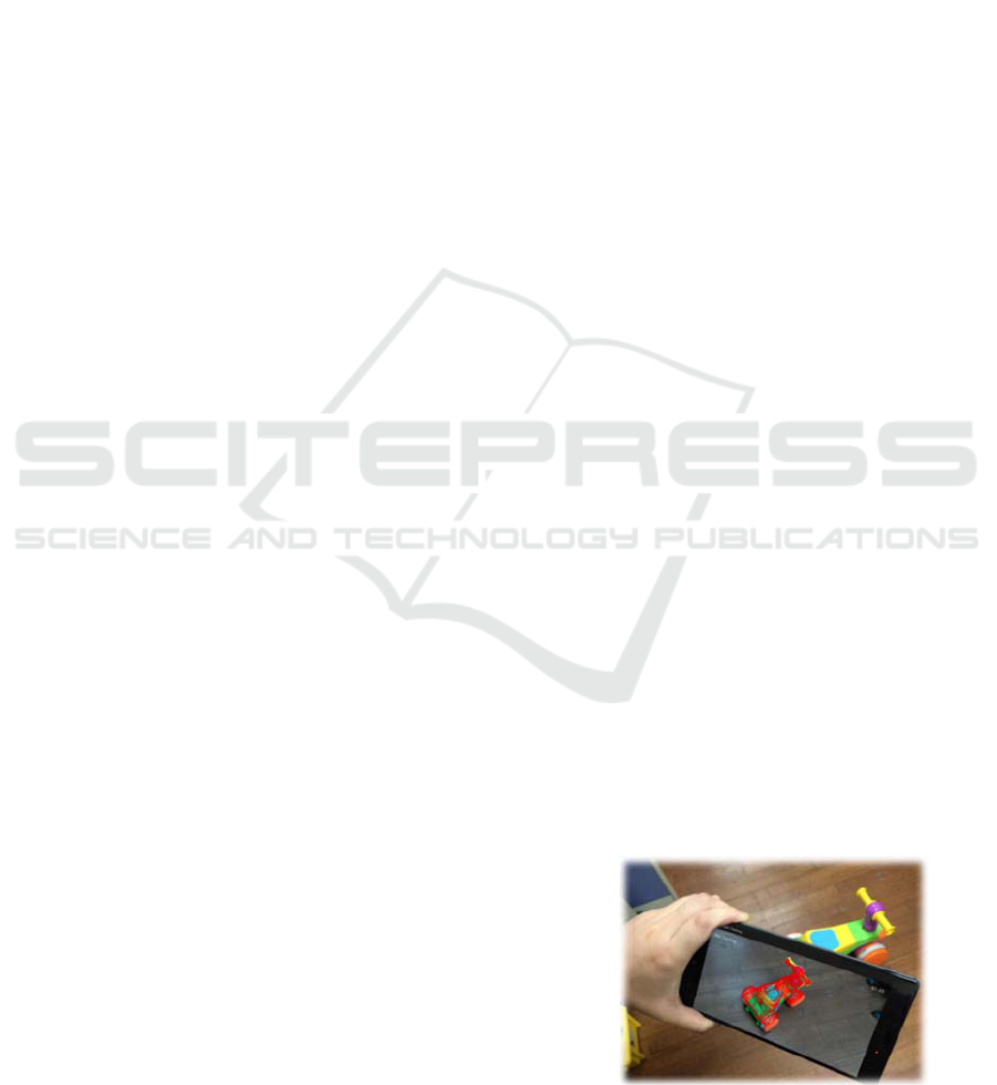
We adopt Lenovo phab 2 pro as our experiment
platform, as shown in Figure 1. This device is a
Google Tango phone, equipped with a color and a
depth camera. To efficiently and robustly match a
foreground object to templates, we adapt a vectorized
normalized cross-correlation (VNCC) algorithm that
vectorizes templates into a dimension-reduced
template matrix. The estimated coarse pose becomes
the initial guess of our bidirectional iterative closest
point (Bidrectional-ICP) algorithm. For further
alleviating the computation burden, we refer to the
sensing data from the inertial measurement unit
(IMU) sensor and predict the short-term movement of
the camera. The experiment demonstrates that the
proposed system can efficiently detect and track
markerless objects with a mobile device for
interactive applications.
Figure 1: The prototype of our system. The object and the
result on the mobile device.
Huang, S., Huang, W., Lu, Y., Tsai, M., Lin, I., Lau, Y. and Liu, H.
Efficient Recognition and 6D Pose Tracking of Markerless Objects with RGB-D and Motion Sensors on Mobile Devices.
DOI: 10.5220/0007692603750382
In Proceedings of the 14th International Joint Conference on Computer Vision, Imaging and Computer Graphics Theory and Applications (VISIGRAPP 2019), pages 375-382
ISBN: 978-989-758-354-4
Copyright
c
2019 by SCITEPRESS – Science and Technology Publications, Lda. All rights reserved
375
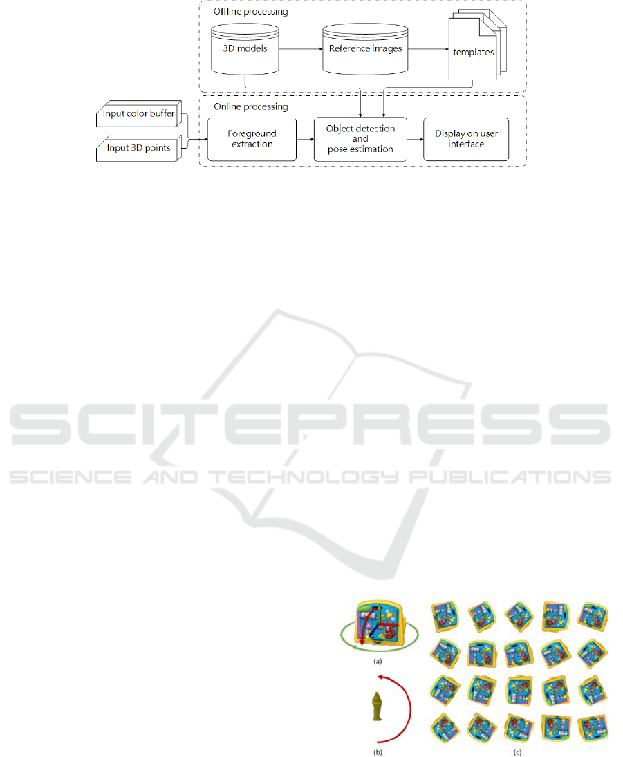
Figure 2: Overview of the whole system.
2 RELATED WORK
3D object detection and pose estimation have been
studied for a long time, and these methods can be
divided into two types, feature-detecting-based
methods, and template-matching-based methods.
Lowe (2004) proposed Scale Invariant Feature
Transform (SIFT) algorithm, which is used to extract
the rotation- and scale-invariant features. Collet et al.,
(2009) used SIFT feature in both 2D image and 3D
model for matching. Aldoma et al., (2013) used SIFT
as the 2D local descriptor and SHOT as the 3D local
descriptor. Both of them showed high accuracy
results on textured objects, however, they are unable
to deal with textureless objects.
Template-matching method is also a practical
solution for detection. Hinterstoisser et al., (2011)
(2012) proposed a real-time template matching
method called LINEMOD, which is able to detect
textureless object quickly. They used multiple
modalities as the features composed of color
gradients and normal orientations. Cao et al., (2016)
restructured template matching as a large-scale
matrix-matrix multiplication to supply a vectorized
normalized cross-correlation algorithm (VNCC). Lin
et al., (2018) decomposed foreground depth images
into multiple branch regions for object matching.
The solution of object pose estimation is derived
from correspondence estimation between two point
clouds, in which one is the set of an object in the scene
and the other is a template or model of the object with
known orientation. Besl and McKay (1992) proposed
the Iterative closest point (ICP) algorithm, which
estimates the rotation and translation between two
point sets iteratively. ICP becomes a widely used
algorithm in aligning 3D models. Korn, Holzkothen
and Pauli (2014) added Lab color space information
into the Generalized Iterative Closest Point (GICP)
algorithm (Segal et al., 2009), a state-of-the-art Plane-
To-Plane ICP variant, to improve the accuracy.
Prisacariu and Reid (2012) proposed a region-
based method, based on statistical level-set
segmentation approaches called PWP3D (Cremers et
al., 2007). It minimizes the differences between 3D
model projective silhouette and the object silhouette
in the image. An extended version of PWP3D on a
mobile phone was then presented (Prisacariu et al.,
2015). However, these silhouette-based methods may
suffer from pose ambiguities with symmetry objects.
Several researches aim at detection and tracking
for mobile devices. Hagbi et al., (2009) used contour
concavities to extract features for real-time pose
estimation and tracking. Seo et al., (2011) proposed a
model-based tracking method that used a 3D model
of the target object and estimated the camera moves
through edge detection and matching. Mohammed
and Morris (2014) tracked the Emergency Exit sign
by using Continuously Adaptive Mean Shift
(CAMShift). Our work adapts the template matching
method proposed by Cao et al., (2016) for object
detection of textureless objects, and then tracks the
postures with an extended ICP method and
adjustment according to the IMU sensing data.
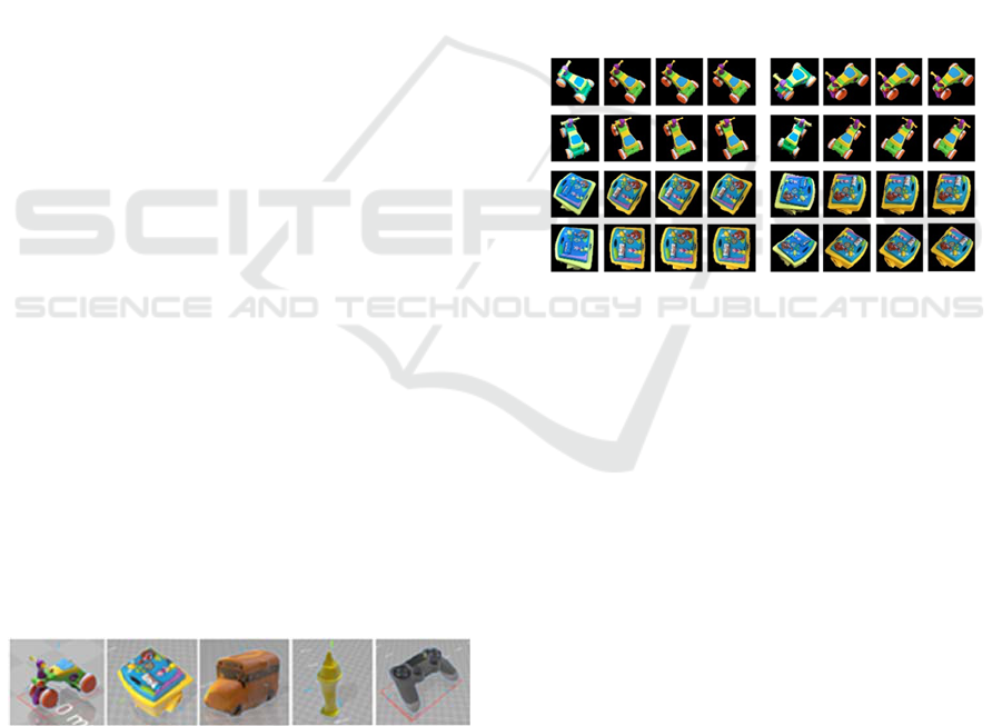
Figure 3: Two types of models and reference images. (a) A
general model. The x-axis is red, y-axis is green and z-axis
is blue. (b) A symmetric model. The viewpoints are
sampled on a semi-circle. (c) Examples of the reference
images generated with (a), in which 24 images are projected
for the in-plane rotation.
GRAPP 2019 - 14th International Conference on Computer Graphics Theory and Applications
376
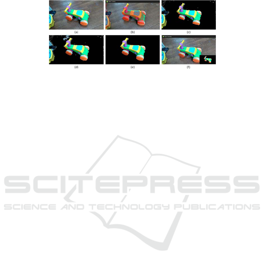
Figure 4: The process of foreground segmentation. (a) The color image from RGB camera. (b) The points extracted from the
segmented plane. (c) The initial foreground projects from points in (b). (d) The foreground spreading result, with noise. (e)
The noise reduction result of (d). (f) The real-time extraction on mobile device.
3 METHOD
The proposed system can be divided into two parts as
shown in Figure 2. The first part is the offline
template generation. The templates are generated by
rendering the 3D models from different viewpoints.
The second part is online processing, including
foreground extraction, object recognition and pose
tracking. The extracted foreground image is matched
with templates to estimate the coarse pose of the
object. Finally, our system renders the 3D model at
estimated pose on user interface to show the tracking
result. Our system aims at a desktop environment. We
assume that the object is placed on a flat plane.
3.1 Reference Images Generation
We generated the reference images (templates) by
rendering the reconstructed 3D model (reconstructed
by Autodesk ReCap) of a target in different
viewpoints. The models can be classified into two
types: general and symmetric. The general model
includes all common models except models that are
rotational symmetric around one of three coordinate
axes. For a general model, we set 5 sample points
around the x-axis and 5 sample points around the y-
axis on a hemisphere as viewpoints (25 in total). For
a symmetric model, we set 13 sample points on a
semi-circle as viewpoints. For each viewpoint, we
rendered 24 samples, 15 degrees apart, around the
direction from the viewpoint to the center of
hemisphere/semi-circle. Examples of reference
images are shown in Figure 3.
3.2 Foreground Extraction
Our system first finds the most likely plane through
the RANSAC algorithm and extract points above the
plane. Since the depth images acquired by the mobile
device are of a low resolution and disturbed by noise,
the RANSAC algorithm can only extract a part of the
plane. Therefore, we need to further extend the
foreground region based on the color information.
Our system projects those points above the plane back
to the relative 2D position in the color image, and
spreads the foreground region according to both depth
data and the color histogram (ab channels of Lab colr
space). It also applies the flood fill algorithm to gather
connected components and removes those of
insufficient point amount. Figure 4 shows the process
of foreground extraction.
3.3 Object Pose Recognition by
Template Matching
We adapted the vectorized normalized cross-
correlation method (Cao et al., 2016) for initial object
and pose recognition. With the vectorized template,
the comparison between template and input image
patch becomes a dot product.
3.3.1 Measurement of Similarity
We convert the foreground image into an intensity
image ∈
and each template into an intensity
image
∈
. is the width of the image, and
is the height of the image,
and
are the width
and height of the template
, ∈
1,2,⋯,
, where
is the number of templates. To compute the cross-
correlation, we resize the foreground image to be the
same as the template size
. For balance of
accuracy and efficiency, in our case, we set
and
to 72 pixels. We apply a Laplacian of Gaussian
(LoG) filter on both image patches and templates for
illumination invariance and then perform mean-
variance normalization on the results of LoG. The
image patch and each template
are now
converted to
and
. Each template
is
Efficient Recognition and 6D Pose Tracking of Markerless Objects with RGB-D and Motion Sensors on Mobile Devices
377
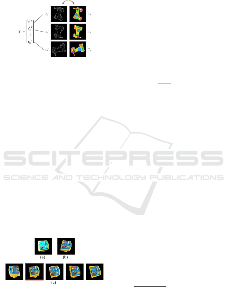
Figure 5: Image template matrix
. Right
is the original
template, Left shows LoG results, and
is the result after
mean-variance normalization. Templates are vectorized
into rows in the template matrix
.
vectorized by concatenating all pixels in the row-wise
order into a column vector
∈
, where is the
number of pixels in the template. We also vectorized
the image patch
into a vector
∈
. The
similarity between
and
is defined below, where
is the mean-normalized cross-correlation result of
each
with
.
(1)
Through vectorizing the templates and image patch,
the matching of a set of templates can be turned into
a matrix-vector multiplication. We transpose
vectorized templates
into rows and use these row
vectors to compose a template matrix
⋯
, as shown in Figure 5. The score vector
∈
is defined as:
,
(2)
where
represents the normalized cross-
correlation score between
and
. The highest
score in can be regarded as the best match of
.
Hence, for matching temples of an object, the best-
match template is the highest-score template in the
score vector and its score has to be higher than the
threshold
.
Figure 6: An example of object pose estimation with
reverse checking. (a) The scene object from foreground
segmentation. (b) The best result of previous frame. (c) The
top 5 templates from left to right, in which the result after
reverse checking is marked in red.
3.3.2 Dimension Reduction of Templates
To speed up the computation of , we apply singular
value decomposition (SVD) on the template matrix
and reduce the dimension of template matrix
.
After SVD,
can be rewritten as:
, (3)
where ∈
, and ∈
are orthogonal
matrices. ∈
is a diagonal matrix of same
dimension of
. We reduce the dimension by
discarding the small singular values in , and keep a
percentage of singular energy as defined below
∑
∑
(4)
can be 90% or more. By selecting the top singular
values in , we can reduce the dimension of and
transform into
∈
. and
are also
transformed into
∈
and
∈
.
Finally, we redefined
as
(5)
3.3.3 Matching with Depth Image
However, we found that if we only consider the color
data, the illumination changes and noise easily
influenced the matching result. Therefore, we also
take the depth information into consideration in
template matching. We repeat the steps in 3.3.1 on
foreground depth image ∈
and template
depth images
∈
. The score vector can
be rewritten as
∗
∗
,
(6)
where
is the color matching score and
is the
depth match score,
and
are used to control the
proportion of
and
. Since the influences of color
and depth vary for different objects, we cannot always
get the best result with fixed weights. Therefore, we
use an entropy method to determine
and
. We
assume that the greater template variation between
different viewpoints, the more information is
provided. We sample templates and calculate the
color similarity score
and depth similarity score
of any two selected templates,
,
,…,
and
,
,…,
. We
normalize
and
into
and
, where
and so as
. The entropy
is defined below
1
10
∑
∑
(7)
GRAPP 2019 - 14th International Conference on Computer Graphics Theory and Applications
378
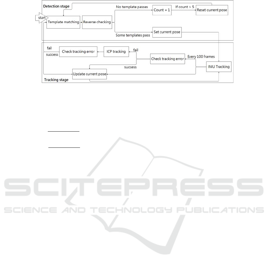
Figure 7: The flow chart shows about switching between two stages and two tracking methods.
Finally, we calculate color entropy
and depth
entropy
then determine entropy weights
and
.
2
(8)
2
(9)
Moreover, sometimes we got the result template of an
opposite rotation angle when the template of these
two viewpoints are too similar. To avoid this
problem, we check if there is a large-angle rotation
between each of the top five result templates of the
current frame and the best result of the previous
frame, using quaternion. Figure 6 shows the result of
template matching with depth image and reverse
checking.
3.4 Object Tracking
After getting the coarse pose by template matching,
we set this pose as the initial pose for tracking. In the
tracking stage, our system switches between two
tracking methods to balance the accuracy and
efficiency of the tracking process. These two tracking
methods are the Bidirectional-ICP tracking and
tracking with IMU sensing data. Figure 7 is the flow
chart shows the switch between detection stage and
tracking stage, and the switch between the
Bidirectional-ICP tracking and tracking with IMU
sensing data.
3.4.1 Bidirectional-ICP Tracking
After setting the initial pose, we use a Bidirectional-
ICP to refine the pose and make it much closer to the
pose of the object in the scene. The Bidirectional-ICP,
an extended version of original ICP algorithm,
searches the corresponding points in two opposite
directions. Assume that the source point set
,
1,2,⋯,
, where
is the number of points of
, and the target point set
, 1,2,⋯,
,
where
is the number of points of ,
,
∈
.
The Bidirectional-ICP not only finds the
corresponding point
∈ for
, but also matches
the corresponding point
∈ for
. We define that
and
are corresponding if the closest point of
is
and the closest point of
is
. A new set is
generated that
, 1,2,⋯,
, where
is the number of the corresponding point pairs.
,
stores the point index from and
respectively. After getting , our Bidirectional-ICP
try to minimize the energy function below and find
the optimal rotation and translation .
,
∗
(10)
In our scenario, the source of the Bidirectional-ICP
is the point cloud of 3D model, and the target is the
point cloud of the object in the scene. Although we
can obtain the point cloud of the scene captured by
the mobile depth sensor, due to its low-resolution,
foreground points extracted above the working plane
are only part of the target object and contain noise.
Matching clustered point cloud is a solution to this
problem; however, clustering is still a time-
consuming approach on the mobile device. Therefore,
we utilize a concept called hidden-surface-removal
template to restrict our ICP model according to
viewpoints (Wu et al. 2016).
In most of the approaches, the source set is the
whole point cloud of the model. Because the target set
is the partial surface of the target object from the
camera viewpoint, if we use the whole model points
in ICP algorithm, there could be more ambiguity on
surface for pose matching. It will increase the chances
to move the point set to unwanted local minimum.
Because the initial poses of the model have been
estimated, we can generate the point cloud from only
Efficient Recognition and 6D Pose Tracking of Markerless Objects with RGB-D and Motion Sensors on Mobile Devices
379
the visible surface of the model. Using the partial
surface point cloud of model not only decreases the
poor estimated pose results, but also reduces the pose
jitter between frames. Even though we use only visible
surfaces as matching templates, there are still unavoid-
ably ambiguous moving directions and it results in
flipping of estimated orientations. To tackle this
problem, we consider the masks and the depth maps of
both object in the scene and the model in estimated
pose to compute the tracking error. If the proportion of
the intersection area and the union area of two masks
decreases or the depth difference in the intersection
area increases, the tracking error will increase. If the
tracking error is too large, our system will leave the
tracking stage and return to detection stage.
3.4.2 Tracking with Assistance of IMU
Sensing Data
Even applying several light-weight processing
strategies, the above-mentioned recognition and
improved ICP algorithms still requires intensive and
iterative computations. From our observation, we
found that a large portion of movement between a
target object and the phone camera results from
camera movement. Therefore, we also adopt the
motion sensing data measured from the IMU sensor
to improve the tracking efficiency. If the movement
of device is slight, we can update the estimated pose
according to the transform matrix from the IMU
sensor. Because tracking with assistance of IMU
sensing data is much faster than tracking with the
Bidirectional-ICP algorithm, our system mainly relies
on tracking with IMU sensing data. However, the
pose drift accumulates after tracking for a period of
time. To solve the accumulated pose drift, we
measure the tracking error every T frames (T=100 in
our case) when tracking with IMU sensing data. If the
tracking error is large, our system will come back to
ICP tracking stage. If the tracking error is still large
after ICP tracking, our system then goes back to
detection state. Figure 7 shows the switch between the
tracking stage.
Figure 8: The models used in our experiment, from left to
right, are ToyCar, Box, Bus, Screw, DS4.
4 EXPERIMENT
Our system is built on Lenovo Phab 2 Pro, which is
equipped with a Qualcomm Snapdragon 652 CPU
and 4GB RAM. The models used in our experiment
are shown in figure 8, ToyCar, Box and Bus are toys,
Screw is a component of ToyCar, DS4 is a controller.
We conducted three experiments to verify the
efficiency and effectiveness of our system. The first
experiment was to evaluate how many template data
should be kept to balance the computation speed and
matching accuracy. We recorded three video clips and
each clip contains more than 500 frames. Then we
performed the detection algorithm with three sizes of
template data. One is the full data without dimension
reduction, another is the data with SVD reduction that
kept 90% singular value energy, and the other is the
data with SVD reduction that kept 80% singular value
energy. Table 1 show the VNCC computation time for
three videos respectively. We can see that the VNCC-
PCA with 80% energy kept is faster than the other two,
and the matching results are as well as the result with
full template data. (Figure 9)
Figure 9: The matching result of the first experiment. Four
images for each frame, from left to right are the input
images, VNCC, VNCC- 90% energy, VNCC- 80% energy.
For evaluating the effectiveness of our method,
we recorded multiple color and depth data of three
different objects with the mobile device. Then we
compared the results with different template match
ing methods. One is matching with color data only,
another is matching with both color and depth data,
and the other is matching with color, depth data and
the additional reverse checking. Finally, we counted
the number of frames with obvious pose error and
computed the error rate. Table 2 shows the results of
error rates. We can see that our template matching
method with color and depth data improves the
matching results.
We also recorded the frames per second (FPS)
when running our system on the mobile device. Table
3 shows the FPS of our system in different stages: (a)
the foreground segmentation, (b) pose recognition,
(c) ICP tracking and (d) tracking with assistance of
device motion sensing data, respectively. Obviously,
the tracking with assistance of IMU sensing data can
substantially increase the computational efficiency.
GRAPP 2019 - 14th International Conference on Computer Graphics Theory and Applications
380
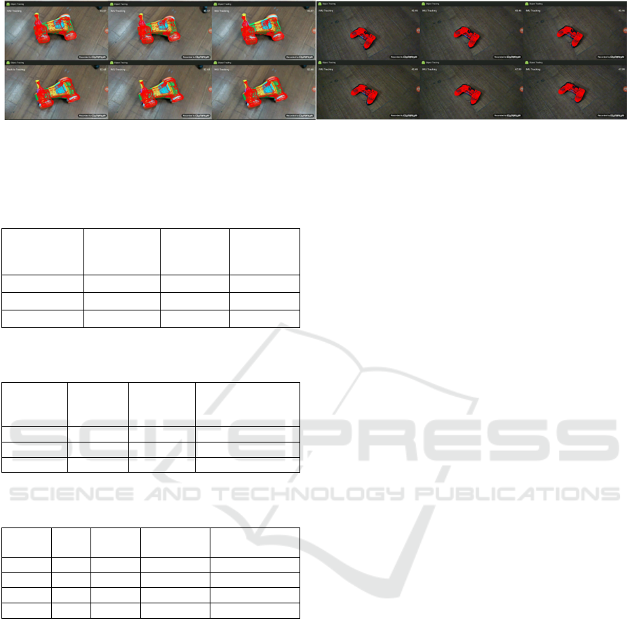
Figure 10: The tracking results of ToyCar and DS4. (3D model points are placed in the estimated 6D posture and are
superposed on the captured image in red.).
Table 1: The test videos and the computation time for
keeping different amounts of template data.
Name#frames
VNCC
(ms/frame)
VNCC-
90% energy
(ms/frame)
VNCC-
80% energy
(ms/frame)
ToyCar#631 4.51 1.52 1.16
Box#865 4.51 1.45 1.12
Screw#504 1.56 0.73 0.50
Table 2: The percentage of frames of which errors are larger
than 20 degrees.
Object
Name
Color
Only
Color and
Depth
Color and Depth
and Rev.
Checking
ToyCa
r
5.28% 0% 0%
Box 15.04% 3.60% 0%
Bus 39.28% 13.69% 0%
Table 3: The efficiency (frames per second) of our system
with different combinations of stages.
Object
Name
(a) (a)+(b) (a)+(b)+(c) (a)+(b) +(c)+(d)
ToyCa
r
17.74 12.17 9.32 53.34
Box 18.94 12.98 9.91 56.68
Screw 18.70 15.63 11.96 50.17
Ds4 14.7 9.94 8.59 53.68
The FPS of Screw is higher than other objects in
ICP tracking but lower in tracking with motion
sensing data. That is because the screw is small in the
camera views, and it is more easily influenced by
noise. When our system finds that the projection
regions from predictions with motion sensing data
and the foreground points are diverse, it leaves the
IMU tracking stage and goes back to the ICP tracking
or detection state, which requires more computations.
Figure 10 shows more tracking results on
different objects. We also provide a video to display
the real situation when running our system on mobile
device.
5 CONCLUSIONS
We proposed a novel system that can detect and track
a textured or textureless object with RGB-D and IMU
sensing data from a mobile device. By vectorizing the
template image into the template matrix and reducing
its dimensions, we can not only reduce the template
set but also more efficiently match the templates.
After detecting the initial pose, our system tracks the
object by our Bidirectional-ICP algorithm. Moreover,
when the relative movement between the object and
the camera are small, our system can check and apply
the sensing data from inertial measurement unit
instead of the full Bidirectional-ICP computation.
Combining the above techniques, the proposed
system can detect and track 6D postures of markerless
objects with a mobile device in an interactive rate. It
can become an efficient platform for mobile AR
applications. One interesting future work is to apply
emerging deep neural network methods on mobile
devices for simultaneously detecting and tracking
multi-objects.
ACKNOWLEDGEMENTS
This paper was supported by Telecommunication
Laboratories, Chunghwa Telecom Co., Ltd. It was
also partially supported by the Ministry of Science
and Technology, Taiwan, under grant no. 106-2221-
E-009 -178 -MY2.
REFERENCES
Aldoma, A., Tombari, F., Prankl, J., Richtsfeld, A., Di
Stefano L. and Vincze, M., 2013. Multimodal cue
integration through Hypotheses Verification for RGB-
D object recognition and 6DOF pose estimation. In
2013 IEEE International Conference on Robotics and
Automation, Karlsruhe, pp. 2104-2111.
Efficient Recognition and 6D Pose Tracking of Markerless Objects with RGB-D and Motion Sensors on Mobile Devices
381

Besl, P. and McKay, N., 1992. A method for registration of
3-D shapes. In IEEE Transactions on Pattern Analysis
and Machine Intelligence, 14(2), pp. 239-256.
Cao, Z., Sheikh, Y. and Banerjee, N.K., 2016. Real-time
scalable 6DOF pose estimation for textureless objects.
In 2016 IEEE International Conference on Robotics
and Automation (ICRA), pp. 2441-2448.
Collet, A., Berenson, D., Srinivasa, S. S. and Ferguson, D.,
2009. Object recognition and full pose registration from
a single image for robotic manipulation. In 2009 IEEE
International Conference on Robotics and Automation,
Kobe, pp. 48-55.
Cremers, D., Rousson, M. and Deriche, R., 2007. A Review
of Statistical Approaches to Level Set Segmentation:
Integrating Color, Texture, Motion and Shape. In
International Journal of Computer Vision, vol. 72, no.
2, pp. 195-215.
Hagbi, N., Bergig, O., El-Sana, J. and Billinghurst, M.,
2009. Shape Recognition and Pose Estimation for
Mobile Augmented Reality. In 8th IEEE International
Symposium on Mixed and Augmented Reality (ISMAR),
pp. 65-71.
Hinterstoisser, S., Cagniart, C., Ilic, S., Sturm, P., Navab,
N., Fua, P. and Lepetit, V., 2012. Gradient Response
Maps for Real-Time Detection of Textureless Objects.
In IEEE Transactions on Pattern Analysis and Machine
Intelligence, 34(5), pp. 876-888.
Hinterstoisser, S., Holzer, S., Cagniart, C., Ilic, S.,
Konolige, K., Navab, N. and Lepetit, V., 2011.
Multimodal Templates for Real-Time Detection of
Texture-less Objects in Heavily Cluttered Scenes. In
Proceedings of the 2011 international conference on
Computer Vision (ICCV), pp. 858-865.
Korn, M., Holzkothen, M. and Pauli. J., 2014. Color
Supported Generalized-ICP. In International
Conference on Computer Vision Theory and
Applications (VISAPP), pp. 592-599.
Lin, J.-Y., She, M.-F., Tsai, M.-H., Lin, I.-C., Lau, Y.-C.,
Liu, H.-H., 2018. Retrieving 3D Objects with
Articulated Limbs by Depth Image Input. In Proc. Intl.
Joint Conf. on Computer Vision, Imaging and
Computer Graphics Theory and Applications, vol. 1
(GRAPP), pp. 101-111.
Lowe, D., 2004. Distinctive Image Features from Scale-
Invariant Keypoints. In International Journal of
Computer Vision, 60(2), pp. 91-110.
Mohammed, A. D. and Morris, T., 2014. A Robust Visual
Object Tracking Approach on a Mobile Device. In 2nd
Information and Communication Technology - EurAsia
Conference (ICT-EurAsia), pp. 190-198.
Prisacariu, V. A., Kähler, O., Murray, D. W. and Reid I. D.,
2015. Real-Time 3D Tracking and Reconstruction on
Mobile Phones. In IEEE Transactions on Visualization
and Computer Graphics (TVCG), pp. 557-570.
Prisacariu, V. A. and Reid, I. D., 2012. PWP3D: Real-Time
Segmentation and Tracking of 3D Objects. In
International Journal of Computer Vision, vol. 98, no.
3, pp. 335-354.
Segal, A. V., Haehnel, D. and Thrun, S, 2009. Generalized-
ICP. In Robotics: Science and Systems.
Seo, B. K., Park, J. and Park, J. I., 2011. 3-D visual tracking
for mobile augmented reality applications. In IEEE
International Conference on Multimedia and Expo
(ICME), pp. 1-4.
Wu, L.-C., Lin, I.-C. and Tsai, M.-H., 2016. Augmented
reality instruction for object assembly based on
markerless tracking. In Proceedings of the 20th ACM
SIGGRAPH Symposium on Interactive 3D Graphics
and Games (I3D '16), pp. 95-102.
GRAPP 2019 - 14th International Conference on Computer Graphics Theory and Applications
382
