
Formal Analysis of Energy Consumption in IoT Systems
Oualid Demigha and Chamseddine Khalfi
Ecole Militaire Polytechnique, Department of Computer Science, PO Box 17, 16111 Bordj El-Bahri, Algiers, Algeria
Keywords:
Internet of Things, IEEE 802.15.4, Energy Efficiency, Model-checking, CSMA/CA, PROMELA, SPIN.
Abstract:
In this paper, we apply model-checking approach to formally analyze energy consumption of the radio in-
terface in order to guarantee network lifetime in the context of the Internet of Things. We propose a joint
MAC-physical model of the IEEE 802.15.4 standard to capture and represent key operations that consume
energy resources of the nodes at the radio interface component. We argue that the combination of the radio
interface ON/OFF state switching mechanism with CSMA/CA medium access method leads to better model-
ing of the energy consumption and help understanding the interaction between MAC and physical layers. Our
model provides accurate representation of simulation models at the first two layers of node’s protocol stack
compliant with IEEE 802.15.4 standard.
1 INTRODUCTION
Internet of Things (IoT) is the next wave of the In-
ternet that may change the world (Lin et al., 2017).
It brings intelligence to ordinary things such as light
switches, heaters, fridges, air conditioners, water sup-
plies, etc. by connecting them to the Internet and
transforming them to smart objects that are able to use
its huge potential of ubiquitous and smart services.
Consequently, they contribute to generating data for
big data analysis and artificial intelligence for better
decision-making and control (CISCO, 2015), (Behera
et al., 2015).
This technology is enabled by the recent advances
in Wireless Sensor Networks (WSN) and low-power
devices with high storage and communication capa-
bilities. It is supported by low energy profile plat-
forms and standards and/or dedicated protocol stacks
for low-rate short and long range communications.
However, the main challenge that faces it in the near
future is the energy problem because most of IoT de-
vices are energy-constrained as they rely on limited-
capacity batteries that are hard to replace or inacces-
sible after being deployed (Burdett, 2015). Addition-
ally, they are intended to function for several months
or years without human intervention. Another techni-
cal obstacle to expand IoT technology is the problem
of dependability because these systems are in perma-
nent interaction with human beings and critical sys-
tems in every-day life. Hence, it is necessary to bring
confidence, reliability and privacy to IoT systems for
technical maturation and large public acceptance.
Therefore, despite the unavoidable interest of ex-
perimental tests and simulation-based performance
studies in tackling the above-mentioned challenges,
formal methods remain a certain way to verify IoT
standards and provide mathematical proofs of cor-
rectness and security. Even more, formal methods
can also be used to guarantee energy performance via
quantified verification of protocol operations. Rely-
ing on a deep understanding of the latter, and via a
rigorous mathematical formalism, these methods can
capture critical operations that consume the energy re-
sources of the network and/or threaten its security.
In this paper, we propose to use one of the most
powerful formal methods, i.e. model-checking to an-
alyze the energy consumption behavior of CSMA/CA
(Carrier Sense Multiple Access with Collision Avoid-
ance) in IEEE 802.15.4 standard. We propose a
simple yet generic and effective joint MAC-physical
model that combines the ON/OFF state switching
mechanism of the radio interface with CSMA/CA in
non-beacon enabled mode of IEEE 802.15.4. By en-
hancing the model in (Rege and Pecorella, 2016),
we are able to integrate a network dimension of LP-
WPAN simulation models and analyze the energy
consumption.
The rest of the paper is organized as follows:
In Section 2, we give a brief description of IEEE
802.15.4 standard with special emphasis on CS-
MA/CA. In Section 3, we present the basics of the
model-checking approach and the linear temporal
Demigha, O. and Khalfi, C.
Formal Analysis of Energy Consumption in IoT Systems.
DOI: 10.5220/0007702801030114
In Proceedings of the 4th International Conference on Internet of Things, Big Data and Security (IoTBDS 2019), pages 103-114
ISBN: 978-989-758-369-8
Copyright
c
2019 by SCITEPRESS – Science and Technology Publications, Lda. All rights reserved
103

logic used to express and evaluate our model. In Sec-
tion 4, we describe our joint MAC-physical model in
terms of state/transition automaton. In Section 5, we
give an implementation of our model in PROMELA
language with the different process automata gener-
ated by SPIN and the energy consumption parameters
of the radio interface. In Section 6, we give a conclu-
sion and future work.
2 IEEE 802.15.4 STANDARD
SPECIFICATION
IEEE 802.15.4 standard offers up to layer 2 a low-
rate short-range communication service with flexible
throughput and latency for wireless personal networks
(Society, 2017). Its extreme low-energy consump-
tion profile and support of most off-the-shelf IoT de-
vices, make it a strong candidate for lower proto-
col stack standard of the Low-Rate Wireless Personal
Area Networks (LR-WPAN), as well as other tech-
nologies such as: Bluetooth Low-Energy (BLE) 4.0,
Bluetooth 5, 5G, etc. (Agerstam et al., 2018).
At the physical layer, IEEE 802.15.4 uses three
different frequency bands, namely: the 868 MHz
band that offers one channel with 20 Kbit/s binary
rate and 1 Km radio range, the 915 MHz band that
offers ten channels each with 40 Kbit/s rate, and the
ISM (Industrial-Scientific-Medical) band (2.4 GHz)
that offers 16 channels at 250 Kbit/s rate. The maxi-
mum radio communication range is 200 m. All these
specifications makes it a flexible data communication
standard with great physical capabilities.
At the MAC layer, IEEE 802.15.4 uses CSMA/CA
method to control access to the medium for mul-
tiple nodes. CSMA/CA is a probabilistic method
based on sensing the communication channels be-
fore sending data to avoid collision between nodes’
frames. Recently, another deterministic MAC method
has been added to IEEE 802.15.4 for reliable commu-
nications in industrial and mission-critical environ-
ments called Time Slotted Channel Hopping (TSCH)
method (Dunagan et al., 2008). In this paper, we fo-
cus only on CSMA/CA modeling that in conjunction
with the radio interface (transceiver) model aims to
reduce the energy consumption to the minimum by
switching OFF the latter for most of the time.
2.1 Operating Modes
IEEE 802.15.4 standard uses four types of frames: (1)
beacon frames that are used by coordinator nodes to
manage the network, (2) data frames that are used to
transfer useful data between nodes, (3) acknowledg-
ment frames that are used to notify the reception of
data frames, and (4) command frames that are used
to request specific commands such as “join the net-
work”.
It offers two operating modes. The first one is
the non beacon-enabled mode called also unslotted
mode where no duty-cycling constraints are specified.
There is no synchronization requirements as nodes
must stay constantly tuned to the radio activity and
continually asking the coordinator node for commu-
nication activities on the channels. Energy consump-
tion in this mode should be high because collisions
are more frequent. The second mode is the beacon-
enabled mode called also slotted mode where nodes
are synchronized via beacon frames. Transmissions
usually start by sending periodic beacon frames by
the coordinator containing network information to in-
form the other nodes about the start, duration and al-
location of each slot (see Figure 1 for a description
of the Superframe). The performance of the MAC
protocol in this mode is higher than in the unslotted
mode in terms of throughput, data delivery, reliabil-
ity and energy consumption because nodes are not re-
quired to stay tunned to sense the radio activity, but
switch off their radio interfaces until their respective
slots arrive. Thus, collisions are reduced to the mini-
mum (without discarding them all) because each node
is programmed to send/receive its data in its specific
slot.
Beacon
CAP
GTS
GTS
GTS
GTS
GTS
Inactive Period
Beacon
Superframe Duration
Inter-beacon Interval
Figure 1: The structure of the Superframe in IEEE 802.15.4.
2.2 CSMA/CA Medium Access Method
CSMA/CA avoids collisions between frames sent by
different nodes by desynchronizing their respective
sending times using a random draw within an inter-
val depending on a backoff exponent. Nodes wait for
their respective random time after which they check
for the availability of the channel. If a node verifies
that the channel is available, then it sends its frame
but with no guarantee that it will reach the receiver
because there may be another node that assesses the
channel and sends its frame at the same time. To rem-
edy to this situation, an acknowledgement mechanism
is provided to notify the well reception of a particular
data frame (Sanabria et al., 2013).
Depending on time representation within the pro-
tocol, two types of medium access methods are de-
fined: slotted CSMA/CA where time is divided into
IoTBDS 2019 - 4th International Conference on Internet of Things, Big Data and Security
104
duration-identical periods called slots at the begin-
ning of which transmissions can be started, and un-
slotted CSMA/CA where transmissions can start at
any arbitrary moment (after sensing the channel and
observing the backoff period). Slotted CSMA/CA is
used in IEEE 802.15.4 beacon-enabled MAC proto-
col mode and unslotted CSMA/CA is used in the non
beacon-enabled mode.
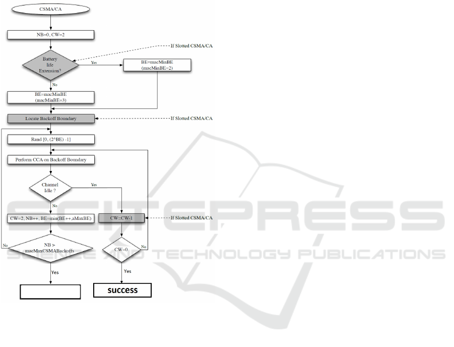
FAILURE
Figure 2: Slotted and unslotted CSMA/CA in IEEE
802.15.4 (Kamgueu, 2017).
Before every frame transmission in slotted CS-
MA/CA, nodes must execute the following steps:
1. Initializing parameters (CW, NB, BE) to their re-
spective default values (see Table 1 for the defini-
tion of these parameters);
2. Drawing a random time (backoff) to desynchro-
nize transmissions;
3. Aligning the beginning of the Unit Backoff Period
(U ) to that of the Superframe. All the nodes must
ensure it remains sufficient time for the backoff
period, the two CW periods, the frame transmis-
sion and the acknowledgement times if it is re-
quested before the end of the Superframe.
4. At the end of the backoff period, the nodes must
check for the channel availability using Clear
Channel Assessment method (CCA) that takes 8
symbols. Three possible cases are to be consid-
ered at the end of CCA:
• If the channel is detected busy, then the node
updates its parameters as follows: NB ← NB +
1, BE ← min(BE +1, MACminBE) and CW ←
CW − 1.
• If NB > MACmaxCSMABacko f f s, then the
node backs-off the transmission of the current
frame. Otherwise, it draws a new backoff time
for another attempt.
• If the channel is detected clear, then the node
decreases its CW parameter (CW ← CW − 1).
If CW = 0, then it sends its frame at the begin-
ning of the next Unit Backoff Period. Other-
wise, it executes another CCA after the current
Unit Backoff Period.
The above procedure differs in unslotted CS-
MA/CA in terms of two points:
• The parameters are decreased immediately after
the backoff period without waiting for the start of
the next Unit Backoff Period because there is no
Superframe; and
• Before transmission in unslotted CSMA/CA,
channel is assessed only once whereas in slotted
CSMA/CA, it is assessed for a double Unit Back-
off Period.
Diagram in Figure 2 shows the flow control of both
slotted and unslotted CSMA/CA.
Most of the literature about CSMA/CA in IEEE
802.15.4 standard do not use formal methods to eval-
uate and verify it (Wu et al., 2018), and focus only
on experimental tests and simulation-based perfor-
mance evaluation (Wu et al., 2014). Furthermore,
even formal-based ones do not consider joint mod-
els of both MAC and physical layers (Kapus, 2017),
especially in the context of energy consumption anal-
ysis in IoT systems (Groß et al., 2007), (Kauer et al.,
2016), (Gawanmeh, 2011). Therefore, in this paper
we apply rigorous model-checking method to analyze
critical protocol operations in IoT systems such as the
IEEE 802.15.4 standard to bring confidence and reli-
ability to them.
3 MODEL-CHECKING
Model-checking is a formal method based on the ex-
ploration of the whole state space of the system under
verification. Assisted by a software tool, this method
checks all the possible scenarios and executions of the
system in a systematic manner. Qualitative proper-
ties such as: safety, liveness, stability, responsiveness,
Formal Analysis of Energy Consumption in IoT Systems
105

Table 1: CSMA/CA Notations.
Term-Notation Description
Unit Backoff Period (U ) Time unit = 20 symbols
Backoff Exponent (BE) Integer initialized by default to MACminBE=3
Backoff
Random waiting time drawn from interval [0, 2
BE
− 1] ×U
Contention Window (CW )
This parameter is only used in slotted CSMA/CA and represents the
number of time units after the backoff time in which the channel
should stay available before transmission
NB Number of current attempts to send, initialized to 0
MACmaxCSMABackoffs
Number of times the channel is found not available before backing-off
current frame transmission, initialized to 3
MACmaxFrameRetries Number of maximum retransmissions of each frame, initialized to 4
invariance, possibility, persistence, fairness, etc., as
well as quantitative properties such as: time to failure,
energy consumption, etc. can be verified by model-
checking. It is one of the most powerful verification
methods because it uses exhaustive analysis of reac-
tive operational systems that include random and/or
probabilistic behavior such as medium access proto-
cols. However, the algorithm behind it is exponen-
tial because it explores the whole state space of the
system
1
. It generates all the possible executions and
verifies the required properties in each of them.
The methodology of model-checking consists of
an abstract model of the system M and a temporal
logical formula φ representing the property to be ver-
ified. The model-checker checks whether M |= φ or
not. It explores the whole state space to prove that
M ∪ {¬φ} has no model. Otherwise, if there is at
least one execution path that satisfies ¬φ, then it out-
puts a counter-example, and the user may conclude
that the property is not verified for that model.
The abstract model can be expressed as Kripke
Automata (Kripke, 1963) or other formalisms (such
as Petri Nets, Finite State Automata, Temporal
Automata, etc.), and the properties can be ex-
pressed in Linear Temporal Logic (LTL), Compu-
tation Tree Logic (CTL), Timed Computation Tree
Logic (TCTL), etc. whose negation is translated to
B
¨
uchi Automata for verification in the model.
3.1 Linear Temporal Logic
Temporal Logic (TL) is an extension of the classi-
cal propositional logic where new temporal connec-
tors are added to express the notion of time. In
statements where temporal expressions such as: “be-
fore”, “after”, “next”, “never”, etc. are used, clas-
sical logic constructions are not sufficient to express
formulas because of their time-independent interpre-
tations (Pnueli, 1977).
1
Research efforts focus on optimizing this aspect
(Clarke et al., 2001).
The execution of a reactive system can be captured
by a sequence of states called trace, noted (σ, i) =<
s
i
→ s
i+1
→ s
i+2
→ ··· >. Each element s
i
in the
trace represents the state of the system where a set
of logical variables is satisfied. Events represent state
change in time, i.e. the evolution of the set of satisfied
variables. If this evolution is linear, then Linear Tem-
poral Logic (LTL) formalism is sufficient to model the
system. Otherwise, formalisms with richer interpreta-
tions of time such as CTL or TCTL are required.
In LTL, a language is a set of formulas constructed
from the combination of a finite set of propositional
symbols and logical connectors. In addition to the
basic logical connectors, a set of temporal connectors
is defined as follows:
1. Next: p which means that “proposition p is
true in the next instant”.
2. Always: p which means that “proposition p is
true in all future instants starting from the current
one“.
3. Finally: ♦p which means that ”proposition p will
be finally true at an arbitrary future instant“.
4. Until: pUq which means that ”proposition p re-
mains true in future instants until proposition q
will be true”.
5. Leads-to: p q which means that “When propo-
sition p becomes true, then proposition q will be
true after that”.
Connectors and U form a complete minimum
set of temporal connectors because we can express the
other connectors as follows:
♦p , >U p
p , ¬♦¬p
p q , (p → ♦q)
The semantic of well-formed formulas of LTL is
defined in terms of traces. A system S verifies a spec-
ification property spec iff every trace of S verifies
IoTBDS 2019 - 4th International Conference on Internet of Things, Big Data and Security
106

spec, i.e. the set of formulas Σ representing S is a
model for the formula φ
spec
representing spec:
∀σ ∈ Exec(S) : (σ, 0) |= φ
spec
Σ |= φ
spec
3.2 Model-checker SPIN
SPIN (Simple Promela INterpreter) is an open source
tool developed by Gerard J. Holzmann (Holzmann,
2003), and used to verify mission-critical industrial
systems written in PROMELA language. PROMELA
(PROcess MEta LAnguage) is a specification lan-
guage for asynchronous and concurrent systems such
as communication protocols, with non-deterministic
control structures. It has a C-like syntax with two
types of finite-state based communication primitives:
global variables and communication channels. A
PROMELA model can be analyzed by SPIN in two
manners: (i) simulation of special cases of the model,
and (ii) verification of the whole model given a certain
property.
SPIN transforms the PROMELA model into a
Kripke structure composed of a map of individual
processes and a finite state Kripke automata repre-
senting the states and the communication channels.
The negation of the LTL formulas are transformed
into B
¨
uchi automata, and the synchronized product
of the two automata is checked whether it is empty or
not: if it is empty, then the system models the formula,
and thus it verifies the property. Otherwise, SPIN out-
puts a trace as a counter-example.
SPIN uses an optimized variant of depth-first
graph traversal algorithm to explore the state space
of the system model called nested depth-first search,
but reduces first the number of reachable states us-
ing an algorithm called partial order reduction. Fur-
ther, it optimizes memory management to represent
huge state spaces using state compression and bit-
state hashing (Holzmann, 2003).
4 OUR JOINT MAC-PHYSICAL
MODEL
Some simulation models of LP-WPAN do not con-
sider realistic energy consumption when using IEEE
802.15.4 standard as a protocol stack. Specifically,
they do not handle radio interface ON/OFF state
switching mechanism in conjunction with beaconless
MAC protocols. Thus, the radio interface is always
ON, which does not meet the real situations in state-
of-the-art hardware and may provide wrong simula-
tion results in terms of energy consumption and delay
metrics.
Therefore, as data transmission/reception is the
main energy-consuming activity of battery-powered
IoT devices, our model aims to define the states/tran-
sitions representing the real energetic characteristics
of an IEEE 802.15.4 based IoT node. It is inspired by
(Rege and Pecorella, 2016), and represents a generic
framework to formally analyze energy consumption
models and ensure their correctness. In particular,
our model combines the radio communication inter-
face behavior with that of CSMA/CA MAC protocol.
The radio interface in (Rege and Pecorella, 2016)
is characterized by the following states:
• TRX OFF: the transceiver is off;
• TX ON: the transmitter is on;
• RX ON: the receiver is on;
• BUSY TX: the transceiver is sending;
• BUSY RX: the transceiver is receiving.
This simple model captures all the possible transitions
of a radio interface compliant with IEEE 802.15.4 in a
two-node communication scenario. However, it does
not consider the network effect due to collisions.
The transmitter (respectively receiver) may have
three states: off, on and busy. For two communi-
cating nodes node1 and node2: if node1 needs to
send a data frame to node2 and their respective ra-
dio interfaces are OFF, then node1 should first turn
its radio interface ON for transmission (transition
TRX
OFF→TX ON). After that, it sends its data frame
to node2 (transition TX ON→BUSY TX). For node2 to
receive a data frame sent by node1, it must first
turn its radio interface ON for reception (transi-
tion TRX OFF→RX ON). This transition is supported
in beacon-enabled mode but requires synchroniza-
tion between node1 and node2 in non-beacon enabled
mode.
After that, node2 changes the radio state to busy
for effective reception (transition RX ON→BUSY RX).
If node2 receives the data frame successfully, then
it sends an acknowledgement in the same man-
ner, then both nodes turn their radio interfaces
OFF (transitions BUSY TX→TX ON→TRX OFF and
BUSY RX→RX ON→TRX OFF respectively).
We enhance this model by handling the network
dimension of IoT systems where collisions may occur
due to the probabilistic nature of CSMA/CA method.
As it is shown in Figure 3, we add a new state called
BACKOFF to abstract the network activity that may lead
to extra-energy consumption caused by collisions.
We modify the semantics of the state/transition
model as follows:
Formal Analysis of Energy Consumption in IoT Systems
107

• IDLE: this state is similar to TRX OFF but it is dif-
ferent from the complete shutdown state. Some
state variables are reset and the transceiver is ca-
pable to assess the channel and detect energy
without using synchronization beacons.
• TX ON: in this state the transmitter is ON (trx =
tx on) but it is not effectively transmitting. Un-
like in model of (Rege and Pecorella, 2016), the
transceiver state does not change immediately to
TRANSMIT without any energy cost. Before trans-
mitting a data frame, a node with a radio interface
compliant with IEEE 802.15.4 should first assess
the channel whether it is clear or not: if it finds
the channel clear (cca = 0), then it sends its data
frame. Otherwise, it changes its state to BACKOFF
to resolve the contention. After the backoff, if it
senses the channel (via low-power listening) and
finds it clear, then it sends its data frame. Other-
wise, the number of attempts is increased at the
MAC layer and the current frame is dropped if it
exceeds 4.
• TRANSMIT in this state, the node is effectively
transmitting its data frame (trx = sending). The
energy consumption: of the node depends on
the time spent in this state and the correspond-
ing voltage. Normally, the radio state should
be clear in this state, but if it is not, then a
collision is reported to the MAC layer. In this
state, the transceiver circuitry may accept another
receiving request but drops all the other trans-
mits. Immediately after finishing the transmis-
sion, the transceiver returns back to TX ON state
to handle other transmitting/receiving operations
if the MAC layer has some frames waiting, then
the channel becomes occupied (cca = 1). In
TX ON state, if there are no transmitting/receiv-
ing operations waiting at the MAC layer, then the
transceiver switches to IDLE state. If an acknowl-
edgement is required, then the transceiver may
change its state directly to RX ON without travers-
ing the IDLE state.
• RX ON: in this state, the transceiver is ready to
receive frames but it is not effectively receiv-
ing them (trx = rx on). If it detects a pream-
ble (preambule = 1), then it changes its state to
RECEIVE for effective reception. If no preamble
is detected, then the transceiver returns back to
IDLE state. When a frame is passed from the MAC
layer to the physical layer, then the transceiver can
change its state directly to TX ON without travers-
ing the IDLE state. Otherwise, it goes to IDLE.
• RECEIVE: in this state, the transceiver is effec-
tively receiving a data or an acknowledgment
frame (trx = receiving). Normally, a preamble
would have been detected before arriving to this
state (preambule = 1). If this is the case, the
frame is passed to the MAC layer to filter it based
on the destination address. If the received frame
is addressed to the current node, then an acknowl-
edgement frame is sent by MAC layer. If the
preamble is missing (preambule = 0), then the
transceiver reports a collision to the MAC layer
and no acknowledgment is sent.
• BACKOFF: in this state, the node waits for the
channel to be clear (trx = backo f f ). If the physi-
cal layer (via low-power listening) detects that the
channel is clear (cca = 0), then it changes its state
to TX ON to resume transmission. Otherwise, the
number of backoffs is increased and if it exceeds
3, then the current frame is dropped.
IDLE
TX_ON
1
TRANSMIT
2
4
3
5
6
7
9
10
8
RX_ON
RECEIVE
BACKOFF
Figure 3: Our joint MAC-physical model.
Table 2 shows the main state variables
used in our model: trx, rmsg, smsg and rid
are controlled by the physical layer, and
data, ack, xdata, rdata, rack, attempt, b attempt
and passed are controlled by the MAC layer.
4.1 Communication Model
Our two-node communication model combines
MAC-triggered with physical-triggered events. The
Link Layer Control (LLC) protocol passes data se-
quentially to the MAC layer upon receiving a noti-
fication that the MAC process is ready. The latter
assigns a unique sequence number to data frames to
track those that have not been acknowledged yet, and
passes them the physical process. The physical pro-
cess does not accept data or acknowledgement frames
while it is busy. Thus, the MAC layer needs to be
notified (using variable passed) that its frame has be
accepted. After transmission, the MAC layer waits
IoTBDS 2019 - 4th International Conference on Internet of Things, Big Data and Security
108

Table 2: State variables used in our joint MAC-Physical model.
Layer Variable Definition
PHY
trx Transceiver state within {idle, tx on, rx on,transmit, receive,backo f f }
rmsg Boolean variable to indicate if the physical layer has received a frame from MAC
smsg
Boolean variable to indicate if the physical layer has received a frame addressed to
MAC
rid Destination address in the received message
MAC
data Sequence number of data frame to send
ack Sequence number of acknowledgment frame waiting for
xdata Expected sequence number of the received data frame
rdata, rack
Sequence number of the received data frames and acknowledgement frames,
respectively
attempt, b attempt Number of sending attempts (backoffs respectively) of a data frame
passed
Boolean variable to indicate that a frame is passed from MAC layer to physical layer
while the transceiver is transmitting or receiving
for an acknowledgement: if it receives one with the
right sequence number, then it notifies the LLC layer.
Otherwise, it drops the acknowledgement frame and
waits for the timer to expire. After timer expiration,
it increases the number of attempts and re-execute the
same process. After a maximum number of attempts,
the MAC layer backs-off the transmission of the cur-
rent frame and notifies the LLC.
Similarly, when the MAC layer receives a data
frame with the expected sequence number (xdata),
then it accepts it and sends an acknowledgement with
the same sequence number. Otherwise, it sends an ac-
knowledgement frame with rdata as a sequence num-
ber.
4.1.1 Transmission
A normal transmission cycle without acknowledge-
ment is as follows:
IDLE → TX ON → [BACKOFF]
∗
→ TX ON
→ TRANSMIT → TX ON → IDLE
The sequence of transitions is shown in Figure 3:
1. Transition 1 is enabled by a MAC layer event indi-
cating that a new data frame is available for trans-
mission. The rmsg variable is set to 1 and the
MAC layer is notified. The residual energy of the
node is updated consequently.
2. Transition 2 is enabled by a physical layer event
that indicates the channel is clear for transmission
(cca = 0). This variable is non-deterministically
set by the radio process described in subsection
4.2. As mentioned in (Rege and Pecorella, 2016),
this transition does not consume energy at the ra-
dio interface level.
3. Transitions 9 and 10 are enabled by a physical
layer event that indicates the channel is not clear
(cca = 1), then becomes clear after the backoff.
Transition TRANSMIT → TX ON is internal to the
radio interface circuitry and it is not observable
by the MAC process. It has zero energy cost.
4. Transition 5 is enabled by a joint MAC-physical
event when rmsg = 0 and the channel is detected
clear (via low-power listening).
When acknowledgements are required, the trans-
mission cycle becomes as follows:
IDLE → TX ON → [BACKOFF]
∗
→ TX ON
→ TRANSMIT → TX ON → RX ON
Transition 7 may reduce reception delays in some
cases (when the sender and receiver are close to each
other and are not too loaded).
4.1.2 Reception
A normal reception cycle of a data frame with ac-
knowledgement is as follows:
[IDLE → RX ON]
∗
→ RECEIVE → RX ON → TX ON
The sequence of transitions is shown in Figure 3:
1. Transition 3 is enabled by the Clear Channel As-
sessment (CCA) function at the physical layer. In
non-beacon enabled mode, nodes must be syn-
chronized to wakeup and assess the channel: if it
detects energy, then it sets smsg variable to 1 and
residual energy is updated consequently.
2. Transition 4 is enabled by a physical layer
event when a preamble of a frame is detected
(preambule = 1). This transition does not con-
sume energy and its reverse transition is integrated
in the circuitry of the radio interface.
3. Transition 8 is enabled by a joint MAC-physical
event that indicates that a new frame is available
for transmission. Variable rmsg is set and the
transceiver changes its state directly to TX ON. In
addition, the MAC layer is notified that its frame
is accepted for transmission.
Formal Analysis of Energy Consumption in IoT Systems
109
Transitions 3 and 6 can be repeated many times as
long as no valid preamble is detected, which is an
energy-consuming cycle.
A normal reception cycle of an acknowledgement
frame does not have transition 8 but has transition 6
instead as shown below:
[IDLE → RX ON]
∗
→ RECEIVE → RX ON → IDLE
Transition 6 is enabled by a physical layer event
(preambule = 0) indicating that no valid preamble is
detected on the occupied channel (cca = 1).
4.2 Radio Model
The radio model represents a multiple access chan-
nel behavior. It is controlled by three variables:
cca, preambule that are set by the radio process and
reset by the nodes, and collision that is set by the
nodes and reset by the radio process.
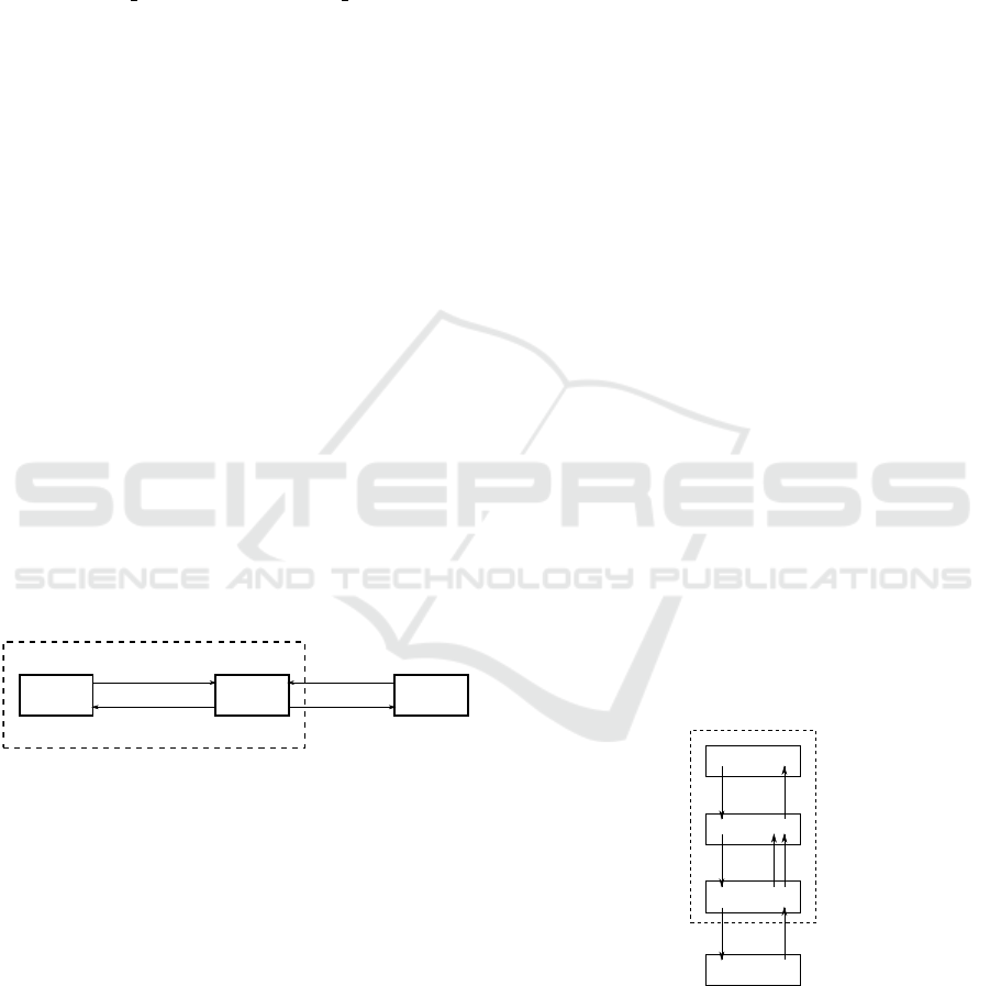
In a three-node communication scenario shown
in Figure 4, transmissions are between node0 and
node1, and node2 is set to send data frames to node1
just to induce collisions. This latter does not acknowl-
edge node2’s frames. Thus, channel out2 is always
empty.
A collision is reported by a transmitting node
(collision = 1) when its transceiver is in state
TRANSMIT with rmsg = 1 and detects that the chan-
nel is not clear (cca = 1). Similarly, when a receiv-
ing node with smsg = 1 whose transceiver state is
RECEIVE and detects no preamble (preambule = 0),
then a collision is also reported.
node 0 node 1 node 2
in
in
out1 out2
Figure 4: Collision representation in 3-node communica-
tion scenario.
Upon detecting a collision, the radio model clears
the channels and reset cca, preambule and collision
variables. It can also inspect the channels and set cca
when in or out1 are not empty, and set preambule
only when channel in is filled by node0 or channel
out1 is filled by node1. preambule is reset by receiv-
ing nodes upon successful reception.
5 IMPLEMENTATION &
VALIDATION
We implement our joint MAC-physical model in
PROMELA. As we show in Figure 5, each node in
three-node communication scenario consists of 3 in-
dependent processes: app, mac and phy representing
the LLC, MAC and physical layer protocols, respec-
tively.
The processes communicate between each others
using the following SPIN channels:
• a2m channel: it has capacity 1, and it is used to
notify the MAC process that a new data message
is available.
• m2a channel: it has capacity 1, and it is used to no-
tify the LLC (app) process that the MAC process
is ready to accept new data frames. In case when
a data frame transmission fails, the MAC process
notifies the LLC process using a negative value
(-1).
• m2p channel: it has capacity 1, and it is used to
pass data and acknowledgement frames from the
MAC layer to the physical layer process with the
corresponding sequence number and the appropri-
ate destination address.
• p2m1 channel: it has capacity 1, and it is used
to notify the MAC process about the admission
of data/acknowledgement frames by the physical
layer process while the transceiver is busy.
• p2m2 channel: it has capacity 1, and it is used
to pass received data/acknowledgement frames to
the MAC layer process.
• in channel: it has capacity 2 to make collisions
possible, and it is used to receive data/acknowl-
edgement frames from the radio process.
• out channel: it has capacity 2 to be able creating
collisions, and it is used to transmit data/acknowl-
edgement frames to the radio process.
app
mac
phy
radio
out
in
node
a2m m2a
m2p
p2m1 p2m2
Figure 5: Model implementation.
The PROMELA source models of the radio, MAC
and physical processes are shown in Figures 7, 9 and
12, respectively.
Additionally, Figure 6 shows the state/transition
automaton of the LLC process that is composed of 7
states and 9 transitions. State S13 is the initial state
IoTBDS 2019 - 4th International Conference on Internet of Things, Big Data and Security
110

from which all the possible executions start. The au-
tomaton is quite simple because the other functions of
LLC such as traffic control, frames numbering, error
control, etc. are not considered in our model. We as-
sume that the MAC layer handles one frame at a time
and all frame buffering and traffic regulation opera-
tions are left for the upper layers.
app
S13
S11
m2a?e
S3
((e==1))
S5
((e==0))
S9
((e==-(1)))
a2m!1 a2m!0
S8
failures = (failures+1)
S10
printf(’%d : failures to send data ’,failures)
a2m!1
Figure 6: State/Transition automaton of the LLC process.
The state/transition automata of the radio, MAC
and physical processes generated by SPIN are de-
picted in Figures 8, 10 and 11.
The state/transition automaton of the radio process
is shown in Figure 8, and it has 21 states and 29 tran-
sitions.
1 p r o c t y p e r a d i o ( ch a n ou t 1 ; c h a n o u t 2 ; ch a n i n ) {
2 mt y pe : msg m;
3 i n t s ;
4 do
5 a s s e r t ( empty ( ou t 2 ) ) ;
6 : : c o l l i s i o n −> / / c l e a r c h a n n e l s
7 i f
8 : : n e m p t y ( i n ) −> i n ?m, s ;
9 : : n e m p t y ( o u t 1 ) −> o u t 1 ?m, s ;
10 : : n e m p t y ( o u t 2 ) −> o u t 2 ?m, s ;
11 : : ( nempty ( i n ) && ne m pty ( o u t 1 ) ) −> at o m i c { i n ?m, s ;
o u t 1 ?m, s ; }
12 : : ( nempty ( i n ) && ne m pty ( o u t 2 ) ) −> at o m i c { i n ?m, s ;
o u t 2 ?m, s ; }
13 : : ( nempty ( o u t 1 ) && ne m p t y ( o u t 2 ) ) −> at o m i c { o u t 1 ?m,
s ; o u t 2 ?m, s ;}
14 : : ( nempty ( i n ) && ne m pty ( o u t 1 ) && nemp t y ( o u t 2 ) ) −>
a t o m i c { i n ?m, s ; o u t 1 ?m, s ; o u t 2 ?m, s ; }
15 f i
16 c c a = 0 ; p r e a m b u l e = 0 ; c o l l i s i o n = 0 ; / / r e s e t
v a r i a b l e s
17 : : ( c c a && n f u l l ( i n ) && empt y ( o u t 1 ) ) −> cc a = 1 ;
p r e a m b u l e = 1 ;
18 : : ( c c a && em p ty ( i n ) && n f u l l ( o u t 1 ) ) −> cc a = 1 ;
p r e a m b u l e = 1 ;
19 od
20 }
Figure 7: PROMELA source model of the radio process.
The automaton of the MAC process has 26 states
and 37 transitions: state S1 is the initial state from
which the MAC process execution starts and state S50
is the one to which all the possible executions return.
It has 6 possible non-deterministic transitions.
Table 3: Energy consumption parameters.
Parameter Value (unit) Definition
MAX EN 1.000.000 Maximum initial
residual energy
TXON 1 Energy consumption
in transition IDLE →
TX ON
RXON 1 Energy consumption
in transition IDLE →
RX ON
TXRX 5 Energy consumption
in transition TX ON →
RX ON
RXTX 5 Energy consumption
in transition RX ON →
TX ON
TX DATA 100 Energy consumption
for transmitting a
data frame
TX ACK 20 Energy consumption
for transmitting an
acknowledgement
frame
RX DATA 80 Energy consumption
for receiving a data
frame
RX ACK 10 Energy consumption
for transmitting an
acknowledgement
frame
The state/transition automaton of the physical pro-
cess has 64 states and 86 transitions. The energy con-
sumption parameters used in our physical model im-
plementation are shown in Table 3. These values are
approximately based on those in (Rege and Pecorella,
2016) which depend on state duration and voltage in
a particular transceiver hardware (AT89RF231), but
can be easily adapted to another one for more accu-
rate model simulation.
6 CONCLUSION & FUTURE
WORK
In this paper, we have proposed a formal joint MAC-
physical model of a radio interface compliant with
IEEE 802.15.4 standard to be used as a framework
for energy consumption simulation of IoT systems.
Our model generalizes the one proposed in (Rege and
Pecorella, 2016) by considering network dimension
and handling extra energy consumption due to colli-
sions and contention resolution procedure. It captures
all the possible transitions induced by the radio in-
Formal Analysis of Energy Consumption in IoT Systems
111

radio
S36
S25
(collision)
S31
(((cca&&nfull(in))&&empty(out1)))
S34
(((cca&&empty(in))&&nfull(out1)))
S3
(nempty(in))
S5
(nempty(out1))
S7
(nempty(out2))
S11
((nempty(in)&&nempty(out1)))
S15
((nempty(in)&&nempty(out2)))
S19
((nempty(out1)&&nempty(out2)))
S24
(((nempty(in)&&nempty(out1))&&nempty(out2)))
S32
cca = 1
S35
cca = 1
S27
in?m,s
out1?m,s
out2?m,s S10
in?m,s
S14
in?m,s S18
out1?m,sS22
in?m,s
S28
cca = 0
S29
preambule = 0
collision = 0
out1?m,s
out2?m,s
out2?m,sS23
out1?m,s
out2?m,s
preambule = 1 preamb
Figure 8: State/Transition automaton of the radio process.
terface ON/OFF state switching and combines them
with the internal functions of the CSMA/CA medium
access method.
We have implemented our model in PROMELA
language and generated the automata of the MAC,
physical and radio processes.
As a future work, we consider to refine the en-
ergy consumption parameters in concordance with the
state-of-the-art transceivers hardware and formulate
specification properties to be verified by our model
such as:
1. The number of frame retransmissions: “if node0
rejects its frame, then the number of unsuccess-
ful transmissions has reached the bound value of
retransmissions”,
2. Hidden senders: “if 2 hidden senders, i.e., node0
and node2 have started their transmissions simul-
taneously, then a collision will occur and will be
1 p r o c t y p e mac ( i n t i d ; c ha n a2m ; c ha n m2a ; cha n m2p ; c ha n
p2m1 ; cha n p2m2 ) {
2 i n t d a t a = 0 ;
3 i n t ac k = 0 ;
4 i n t x d a t a = 1 ;
5 i n t e v e n t ;
6 i n t r d a t a , r a c k ;
7 i n t a t t e m p t = 0 ;
8 mt y pe : msg msgT ;
9 i n t s e q ;
10 b o o l p a s s e d = 0 ;
11
12 m2a ! 1 ;
13 do
14 : : a2m? e v e n t −>
15 i f
16 : : e v e n t −> d a t a = ( d a t a + 1 )%MAX; a t t e m p t = 0 ;
17 : : e l s e −> s k i p ;
18 f i
19 : : ( d a t a == ( ack + 1) ) −> m2p !DATA( d a t a ) ; a ck = ( ac k
+ 1 )%MAX;
20 : : p2m1? msgT , se q , p a s s e d −>
21 i f
22 : : ! p a s s e d −> m2p ! msgT ( se q ) ;
23 : : e l s e −> s k i p ;
24 f i
25 : : p2m2?DATA( r d a t a ) −>
26 i f
27 : : ( r d a t a == x d a t a ) −> m2p !ACK( x d a t a ) ; x d a t a = (
x d a t a + 1 )%MAX;
28 : : e l s e −> m2p !ACK( r d a t a ) ;
29 f i
30 : : p2m2?ACK( r a c k ) −>
31 i f
32 : : ( r a c k == a c k ) −>m2a ! 1 ;
33 : : e l s e −> s k i p ;
34 f i
35 : : t i m e o u t −>
36 i f
37 : : p a s s e d −> a t t e m p t = ( a t t e m p t + 1 ) ;
38 i f
39 : : ( ( a t t e m p t < MAX ATTPT) | | ( i d == 2) ) −> m2p !
DATA( d a t a ) ;
40 : : e l s e −> a t t e m p t = 0 ; p r i n t f ( ” F a i l u r e t o s e n d
d a t a / ack : %d\n ” , d a t a ) ; m2a ! −1;
41 f i
42 : : e l s e −> s k i p ;
43 f i
44 od
45 }
46
Figure 9: PROMELA source model of the MAC layer pro-
cess.
detected by the receiver”,
3. Maximum probability of at least k collisions, and
4. Minimum energy consumption of at most k colli-
sions.
We also consider to simulate some special cases
of two-node and three-node communication scenarios
to evaluate our model in terms of the number of data
transmission failures, the number of collisions and the
amount of energy consumption consumed in the con-
tention resolution procedure.
IoTBDS 2019 - 4th International Conference on Internet of Things, Big Data and Security
112

mac
S1
S50
m2a!1
S8
a2m?event
S11
((data==(ack+1)))
S18
p2m1?msgT,seq,passed
S26
p2m2?2,rdata
S33
p2m2?1,rack
S48
(timeout)
S4
(event)
S7
else
S12
m2p!2,data
S15
(!(passed))
S17
else
S22
((rdata==xdata))
S25
else
S30
((rack==ack))
S32
else
S37
(passed)
S47
else
S5
data = ((data+1)%100)
(1)
attempt = 0
ack = ((ack+1)%100) m2p!msgT,seq (1)
S23
m2p!1,xdata
m2p!1,rdata
xdata = ((xdata+1)%100)
m2a!1 (1)
S44
attempt = (attempt+1)
(1)
S39
(((attempt<4)||(id==2)))
S41
else
m2p!2,data
S42
attempt = 0
S43
printf(’Failure to send data/ack: %d ’,data)
m
Figure 10: State/Transition automaton of the MAC layer
process.
REFERENCES
Agerstam, M., Colby, R., Donohue, P., Meyer, S. J., and
Sanghadia, P. (2018). Reduce iot cost and enable scal-
ing through open wireless sensor networks. White pa-
per, Intel Corp.
Behera, R. K., Gupta, S., and Gautam, A. (2015). Big-
data empowered cloud centric internet of things. In
Proceedings of the International Conference on Man
and Machine Interfacing, MAMI.
Burdett, A. (2015). Ultra-low-power wireless systems:
Energy-efficient radios for the internet of things. IEEE
Solid-State Circuits Magazine, 7(2):18–28.
CISCO (2015). Fog computing and the internet of things:
phy
S119
S2
((trx==7))
S13
((trx==6))
S29
((trx==5))
S46
((trx==4))
S69
((trx==3))
S98
((trx==2))
S116
((trx==1))trx = 6
S5
m2p?rmsgT,rmsg_seq
S10
(nempty(in))
S21
(rmsg)
S24
(nempty(in))
S28
((!(rmsg)&&empty(in)))
S37
(smsg)
S40
m2p?rmsgT,rmsg_seq
S45
((!(smsg)&&empty(m2p)))
S53
((rmsg&&!(cca)))
S61
m2p?rmsgT2,rmsg_seq2
S63
((!(rmsg)&&empty(m2p)))
S67
((rmsg&&cca))
S76
((smsg&&preambule))
S92
(!(smsg))
S96
((smsg&&!(preambule)))
S103
(!(cca))
S107
(timeout)
S6
rmsg = 1
S11
smsg = 1
S7
p2m1!rmsgT,rmsg_seq,1
S8
trx = 5
energy = (energy-1)
S12
trx = 4
energy = (energy-1)
S18
(!(cca))
S20
(cca)
S25
smsg = 1
trx = 6
trx = 3trx = 1
S26
trx = 4
energy = (energy-5)
S34
(preambule)
S36
(!(preambule))
S41
rmsg = 1
trx = 6
trx = 2trx = 6
S42
p2m1!rmsgT,rmsg_seq,1
S43
trx = 5
energy = (energy-5)
S51
out!rmsgT,id,rmsg_seq
S71
p2m1!rmsgT2,rmsg_seq2,0
(1)
S66
rmsg = 0
S52
rmsg = 0
S58
cca = 1
S55
((rmsgT==2))
S57
((rmsgT==1))
energy = (energy-100) energy = (energy-20)
trx = 5
S68
collision = 1
printf(’TX: collision ’)
S75
in?smsgT,rid,smsg_seq
S100
(1)
S95
collision = 1
S82
preambule = 0
S78
((rid==(1-id)))
S81
else
S79
p2m2!smsgT,smsg_seq
S84
(1)
smsg = 0
S89
preambule = 0
S86
((smsgT==2))
S88
((smsgT==1))
energy = (energy-80)energy = (energy-10)
trx = 4
S97
smsg = 0
printf(’RX: collision ’)
S104
b_attempt = 0
S114
b_attempt = (b_attempt+1)
trx = 5
S109
((b_attempt<3))
S111
else
(1)
S112
b_attempt = 0
trx = 6
Figure 11: State/Transition automaton of the physical layer
process.
Extend the cloud to where the things are. Technical
report, CISCO Corp.
Clarke, E., Grumberg, O., Jha, S., Lu, Y., and Veith, H.
(2001). Progress on the state explosion problem in
model checking. Informatics. 10 Years Back. 10 Years
Ahead, LNCS 2000, pages 176–194.
Formal Analysis of Energy Consumption in IoT Systems
113

Dunagan, J. D., Bahl, P., and Chandra, R. (2008). Slotted
seeded channel hopping for capacity improvment in
wireless networks.
Gawanmeh, A. (2011). Embedding and verification of zig-
bee protocol stack in event-b. Procedia Computer Sci-
ence, 5:736–741.
Groß, C., Hermanns, H., and Pulungan, R. (2007). Does
clock precision influence zigbee’s energy consump-
tions? In Tovar, E., Tsigas, P., and Fouchal, H., ed-
itors, Principles of Distributed Systems, pages 174–
188, Berlin, Heidelberg. Springer Berlin Heidelberg.
Holzmann, G. J. (2003). The SPIN MODEL CHECKER:
Primer and Reference Manual. Addison-Wesley Pear-
son Education, first edition.
Kamgueu, P. O. (2017). Configuration Dynamique et
routage pour l’internet des objets. PhD thesis, Uni-
versity of Lorraine (France), University of Yaound
´
e.
Kapus, T. (2017). Using prism model checker as a vali-
dation tool for an analytical model of ieee 802.15.4
networks. Simulation Modelling Practice and Theory,
77:367 – 378.
Kauer, F., K
¨
ostler, M., L
¨
ubkert, T., and Turau, V. (2016).
Formal analysis and verification of the ieee 802.15.4
dsme slot allocation. In Proceedings of the 19th ACM
International Conference on Modeling, Analysis and
Simulation of Wireless and Mobile Systems, MSWiM
’16, pages 140–147, New York, NY, USA. ACM.
Kripke, S. (1963). Semantical considerations on modal
logic. Acta Philosophica Fennica, 16:83–94.
Lin, J., Yu, W., Zhang, N., Yang, X., Zhang, H., and Zhao,
W. (2017). A survey on internet of things: Archi-
tecture, enabling technologies, security and privacy,
and applications. IEEE Internet of Things Journal,
4(5):1125–1142.
Pnueli, A. (1977). The temporal logic of programs. In
Proceedings of the 18th Annual Symposium on Foun-
dations of Computer Science, SFCS’77, pages 46–57,
Washington, DC, USA. IEEE Computer Society.
Rege, V. and Pecorella, T. (2016). A realistic mac and en-
ergy model for 802.15. 4. In Proceedings of the Work-
shop on ns-3, pages 79–84. ACM.
Sanabria, L., Faridi, A., adn Jaume Barcelo, B. B., and
Olivier, M. (2013). Future evolution of csma proto-
cols for the ieee 802.11 standard. In Second IEEE ICC
Workshop On Telecommunication Standards: From
Research to Standards.
Society, I. C. (2017). Ieee 802.15.4-2017 - ieee standard for
low-rate wireless networks. Electronic.
Wu, B., Lemmon, M. D., and Lin, H. (2018). Formal
methods for stability analysis of networked control
systems with ieee 802.15.4 protocol. IEEE TRANS-
ACTIONS ON CONTROL SYSTEMS TECHNOLOGY,
26(5):1635–1645.
Wu, S., Mao, W., and Wang, X. (2014). Performance study
on a csma/ca-based mac protocol for multi-user mimo
wireless lans. IEEE Transactions on Wireless Com-
munications, 16(6):3153–3166.
1 p r o c t y p e phy ( i n t i d ; ch an i n ; ch a n o u t ; chan m2p ; chan p2m1 ;
chan p2m2 ) {
2 m typ e : s t a t e t r x = s t a r t ;
3 i n t e n e r g y = MAX EN;
4
5 b o o l rmsg = 0 ;
6 i n t r m s g s e q = 0 , r m s g s e q 2 = 0 ; / / s e q . No . o f c u r r e n t d a t a /
ack r e c ei v e d f r o m MAC
7 m typ e : msg rmsgT ;
8 m typ e : msg rmsg T2 ; / / me s s a g e r e c e i v e d from MAC
9 i n t b a tt e m p t =0 ;
10 b o o l smsg = 0 ;
11 i n t s m s g s e q = 0 ; / / s e q . No . o f c u r r e n t d a t a / a c k r e c e i v e d t o
MAC
12 m typ e : msg smsgT ; / / me s s a g e s e n t t o MAC
13 i n t r i d ;
14
15 do
16 : : t r x == s t a r t −> t r x = i d l e
17 : : t r x == i d l e −>
18 i f
19 : : m2p ? rmsgT , r m s g se q −>
20 rmsg = 1 ; p2m1 ! rmsgT , r m s g se q , 1 ; t r x = t x o n ;
21 e n e r g y = e n e r g y − TXON;
22 : : nemp ty ( i n ) −> smsg = 1 ; t r x = r x on ;
23 e n e r g y = e n e r g y − RXON ;
24 f i
25 : : t r x == t x on −>
26 i f
27 : : rms g −>
28 i f
29 : : ! c c a −> t r x = t r a n s m i t ;
30 : : c c a −> t r x = b a c k o f f ;
31 f i
32 : : ( ne mpt y ( i n ) ) −> smsg = 1 ; t r x = r x on ;
33 e n e r g y = e n e r g y − TXRX;
34 : : ( ! r ms g && em pty ( i n ) ) −> t r x = i d l e ;
35 f i
36 : : t r x == r x on −>
37 i f
38 : : smsg −>
39 i f
40 : : p r e a m b u l e −> t r x = r e c e i v e ;
41 : : ! p r e a m b u l e −> t r x = i d l e ;
42 f i
43 : : m2p ? rmsgT , r m s g se q −>
44 rmsg = 1 ; p2m1 ! rmsgT , r m s g se q , 1 ; t r x = t x o n ;
45 e n e r g y = e n e r g y − RXTX ;
46 : : ( ! smsg && em pty ( m2p ) ) −> t r x = i d l e ;
47 f i
48 : : t r x == t r a n s m i t −>
49 i f
50 : : ( rmsg && ! c c a ) −>
51 a t o m i c { o u t ! rmsgT , i d , r m s g se q ; rmsg = 0 ; c c a = 1 ; }
52 i f
53 : : rmsgT == DATA −> e n e r g y = e n e r g y − TX DATA ;
54 : : rmsgT == ACK −> e n e r g y = e n e r g y − TX ACK;
55 f i
56 : : m2p ? rmsgT2 , r m s g s e q 2 −> p2m1 ! rmsgT2 , r m s g s e q2 , 0 ;
57 : : ( ! r ms g && em pty ( m2p ) ) −> sk i p ;
58 : : ( rmsg && c c a ) −> at o m i c { rmsg = 0 ; c o l l i s i o n = 1; }
59 p r i n t f ( ”TX: c o l l i s i o n \ n ” ) ;
60 f i
61 t r x = t x o n ;
62 : : t r x == r e c e i v e −>
63 i f
64 : : ( smsg && p r e a m b u l e ) −>
65 a t o m i c { i n ?smsgT , r i d , s m s g s e q ; p r e a m b u l e = 0; }
66 i f
67 : : r i d == 1−i d −> p2m2 ! smsgT , s m s g s e q ; smsg = 0 ;
68 : : e l s e −> s k i p ;
69 f i
70 p r e a m b u l e = 0 ;
71 i f
72 : : smsgT == DATA −> e n e r g y = e n e r g y − RX DATA;
73 : : smsgT == ACK −> e n e r g y = e n e r g y − RX ACK;
74 f i
75 : : ! smsg −> s k i p ;
76 : : ( smsg && ! p r e a m b u l e ) −> a t o m i c { c o l l i s i o n = 1 ; smsg = 0 ; }
77 p r i n t f ( ”RX: c o l l i s i o n \ n ” ) ;
78 f i
79 t r x = r x on ;
80 : : t r x == b a c k o f f −>
81 do
82 : : ! c c a −> b a t t e m p t = 0 ; t r x = t x o n ; b r e a k ;
83 : : t i m e o u t −>
84 b a t t e m p t = ( b a t t e m p t + 1) ;
85 i f
86 : : ( b a t t e m p t < MAX BACKOFFS) −> s k i p
87 : : e l s e −> b a t t e m p t = 0 ; t r x = i d l e ; b r e a k ;
88 f i
89 od
90 od
91 }
Figure 12: PROMELA source model of the physical layer
process.
IoTBDS 2019 - 4th International Conference on Internet of Things, Big Data and Security
114
