
Design of an Example Network Protocol for Security Tests Targeting
Industrial Automation Systems
Steffen Pfrang
a
, Mark Giraud, Anne Borcherding, David Meier
b
and J
¨
urgen Beyerer
Fraunhofer IOSB, Karlsruhe, Germany
Keywords:
Security Testing, Industrial Automation and Control Systems, IACS, Example Network Protocol, Packet
Structure, Protocol Behavior.
Abstract:
Emerging concepts like Industrial Internet of Things (IIOT) and Industrie 4.0 require Industrial Automation
and Control Systems (IACS) to be connected via networks and even to the Internet. These connections raise
the importance of security for those devices enormously. Security testing for IACS aims at searching for
vulnerabilities which can be utilized by attackers from the network. Once discovered, those gaps should be
closed with patches before they can get exploited. Different tools utilized for this kind of security testing are
dealing with network protocols. In practice, they suffer from peculiarities being present in common industrial
automation protocols like OPC UA and Profinet IO. This paper tries to improve the situation by providing an
extensive overview of network packet structures and network protocol behavior. Based on this analysis, an
example protocol has been developed. The idea behind this artificial network protocol is that tools which are
able to handle all the specialties of this protocol, are able to handle every imaginable protocol. Finally, those
tools can be used to conduct exhaustive security tests for IACS.
1 INTRODUCTION
Security testing for industrial automation and cont-
rol systems is gaining more and more importance. As
emerging concepts and techniques from Industrial In-
ternet of Things and Industrie 4.0 require sensors, ac-
tuators and controllers to be connected via networks
and the Internet, security becomes a critical factor. In
former times, security did not play a major role in
industrial devices as they were run in separated net-
works. But since the adaption of Ethernet, IACS com-
ponents have to resist attacks originating from other
networks, such as office networks or even the whole
world.
Security testing aims at discovering vulnerabilities
to enable IACS manufacturers to patch their devices
before attackers can exploit them. A common appro-
ach for security testing is fuzzing. Fuzzing network
protocols means sending meaningfully chosen input
as payload in network packets to a device under test
(DUT). Advanced fuzzing techniques take into ac-
count both packet structures and states of the protocol
to be fuzzed. This allows for choosing input with a
a
https://orcid.org/0000-0001-7768-7259
b
https://orcid.org/0000-0003-0660-8087
higher probability of being interpreted by the DUT.
Tools dealing with packet structures and states of
network protocols are usually developed for and tes-
ted with well-known protocols. Examples for such
tools are self-learning fuzzers which construct a pac-
ket and state model of a specific network protocol by
using packet captures. Other tools are meant for craf-
ting network packets or tracing the state of a stateful
network protocol. Since especially industrial proto-
cols like Profinet IO or OPC UA use special concepts,
many of the tools lack functionality to deal with them.
An example for such a missing feature are infinite re-
cursive data types which are used in OPC UA. There
is a lack of a common standard protocol which fits all
the needs.
The idea to overcome this issue is the specifica-
tion of an example protocol which makes use of all
the concepts discovered in both standard Internet pro-
tocols and real world industrial protocols. Tools to be
developed or maintained can be tested with this ex-
ample protocol. If the tool is able to handle all the re-
quirements of the example protocol, it should be able
to implement every industrial protocol.
This paper presents a requirement analysis for the
needs of common network protocols and the design of
such an example protocol. Additionally, a reference
Pfrang, S., Giraud, M., Borcherding, A., Meier, D. and Beyerer, J.
Design of an Example Network Protocol for Security Tests Targeting Industrial Automation Systems.
DOI: 10.5220/0007704907270738
In Proceedings of the 5th International Conference on Information Systems Security and Privacy (ICISSP 2019), pages 727-738
ISBN: 978-989-758-359-9
Copyright
c
2019 by SCITEPRESS – Science and Technology Publications, Lda. All rights reserved
727

implementation is released to the public to enable se-
curity researchers to use it.
The paper is structured as follows: Starting with
introducing the background in Section 2, the analysis
in Section 3 presents three use cases for the example
protocol. Two common industrial protocols are ex-
amined more closely, before a packet field categori-
zation prepares the collection of the requirements for
the example protocol. The example protocol is de-
signed in Section 4 with both protocol behavior and
packet structures. Finally, a case study in Section 5
illustrates the usage of the example protocol.
2 BACKGROUND
The research of this paper is located in different dom-
ains: Industrial automation, security testing and net-
work protocol design. All domains will be presented
shortly in the following.
2.1 Industrial Automation
Physical equipment in industrial environments is mo-
nitored and controlled by industrial automation and
control systems (IACS). With their reliance on pro-
prietary hardware, software, and networks, these sy-
stems have often been considered too complex to be
attacked. In addition, IACS have often been located
in local networks with no connection to the Internet.
As the systems and network protocols evolve,
these points are no longer valid. Systems and net-
works move towards open standards like Ethernet,
TCP/IP and web technologies. In addition, IACS are
more and more connected to the Internet. This de-
velopment makes the IACS more interesting for hac-
kers. The most popular example for a successful at-
tack on IACS is Stuxnet (see (L
¨
uders, 2011)). The
effects of a successful attack on IACS range from a
manipulation or disruption of the production process
to personal or environmental damage or loss.
2.2 Security Testing
It is crucial to ensure the security of IACS to avoid the
effects of a successful attack. One aspect of this is to
identify vulnerabilities and to ensure security functio-
nality. It is called security testing and includes many
different techniques. These techniques may be classi-
fied into four categories which are presented in Table
1. The classification and the corresponding descripti-
ons are adapted from (Felderer et al., 2016) as long as
not stated otherwise.
Table 1: Classification of security testing techniques (adap-
ted from (Felderer et al., 2016)).
model-based security testing
... for web applications
... for security policies
risk-based security testing
code-based testing and static analysis
manual code review
static application security testing
penetration testing and dynamic analysis
penetration testing
vulnerability scanning
dynamic taint analysis
fuzzing
security regression testing
test suite minimization
test case prioritization
test case selection
Model-based security testing presumes the exis-
tence of architectural and functional models of the sy-
stem under test. From these models, test cases for the
security test are derived systematically. Because of
the need of precise models, these techniques require
an early and explicit specification. The models may
be driven by the concrete system, by security policies,
or by risks.
Code-based testing and static analysis focuses on
the code of a system. No running system is needed to
apply these techniques. The review of the code can
either be done manually or automatically.
Penetration testing and dynamic analysis can be
conducted if a running version of the system is availa-
ble. These techniques do not need access to the source
code of the system and are thus also called black box
testing. Security tests are performed by interacting
with the running system. This includes manual pene-
tration testing, automated scanning for known vulne-
rabilities, dynamic analysis of data sanitization, and
fuzzing. Fuzzing uses random or randomly modified
data and feeds it to the system. With this, the reaction
of the system to unexpected data can be investiga-
ted which may expose vulnerabilities (Pfrang et al.,
2018).
Security regression testing aims to ensure that a
change of a system does not downgrade the security
of the system. To be able to conduct these test effi-
ciently, the test suite can be minimized, the test cases
can be prioritized and the test cases can be selected in
an optimized way.
Each of the presented techniques is located at dif-
ForSE 2019 - 3rd International Workshop on FORmal methods for Security Engineering
728

Analysis Design Devel. Depl.
Operation
model-
based
code-
based
pen-
tests
security
regr.
Security
Reqmts.
Risk
Analysis
External
Review
Risk
Analysis
Field
Feedback
Figure 1: Security testing techniques at different stages of
the system development.
ferent stages of the system development. This is
shown in Figure 1. Presented are the stages of the
system development, adapted from (Felderer et al.,
2016): Analysis, Design, Development, Deployment,
and Operation (Maintenance). On top of the arrow,
the security testing techniques which may be used
in the respective stages are shown. Additional input
which may be used for testing is depicted underneath
the arrow (Potter and McGraw, 2004).
Next to the shown classification, a classification
using other dimensions is possible. For example, se-
curity testing techniques could be classified regarding
their accessibility (black-box vs. white box), scope
(component vs. integration vs. system), objective
(functional vs. non-functional), user interaction (ma-
nual vs. automated), and their practice (active vs. pas-
sive).
2.3 Network Protocol Design
Communication between programs and services of
host systems is commonly achieved through the usage
of network protocols.
2.3.1 Protocol Goals and Features
Network protocols provide features to achieve diffe-
rent communication goals. They have varying proper-
ties, that connected applications rely on, to achieve
these goals. These properties include (Peterson and
Davie, 2007):
• Message Delivery Guarantees: The protocol
makes sure that messages get delivered. If a mes-
sage is lost during transmission, the protocol can
initiate additional delivery attempts.
• Maintaining Data Order: A network protocol
can make sure that the receiving application gets
the data served in its original order, independent
from packet order changes that might happen du-
ring the transport.
• Filtering of Duplicates: During transport packets
can get duplicated, e.g. because of retransmissi-
ons or multi-path transmission. These duplicates
can be automatically identified and dropped by a
network protocol.
• Support of Large Messages: A sender might
want to transmit data that exceeds the frame limit
of the carried medium or link technology. A pro-
tocol could automatically split the message into
multiple smaller ones and reassemble them at the
receiver.
• Flow and Congestion Control: The maximal
data rate between sender and receiver is determi-
ned by different factors, like the maximum capa-
city of the communication channel and the resour-
ces of the receiver. Network protocols can auto-
matically adjust the sending rate accordingly.
• Application Separation: Protocols can help to
ensure that data from different applications stays
separated, even when transmitted via the same
communication link.
Most of these properties and features are provi-
ded transparently to the different layers of the proto-
col stack. This stack can be organized into layers to
achieve a high rate of adaptability. In this layer model,
each protocol layer is providing services other layer
can utilize (Kurose and Ross, 2013). The Open Sys-
tems Interconnection model (ISO, 1994), often called
ISO/OSI model, or the internet protocol stack (Bra-
den, 1989) formalize this approach.
Above the Physical layer, which handles the trans-
mission of information over a certain channel me-
dium, the Link layer deals with packet frames that are
transmitted from one node to another. Data transmis-
sion of datagrams over multiple nodes is handled by
the Network layer. It is also responsible for finding
appropriate routes between two nodes. The Transport
layer handles segments and transmits data between
two application instances. On the Application layer,
transmitted data is referred to as messages.
2.3.2 Protocol Definitions
Individual protocols are defined by their multiple pro-
perties. The main properties of a protocol are the
structures of its protocol data units (PDU) and its be-
havioral description.
Because the actual transmission is carried out on
binary data, the data needs to be serialized at the sen-
der and parsed at the receiver to enable the proper pro-
cessing of the PDU. A basic division of a PDU can
be done by separating meta data (header) and the ac-
tual data that needs to be transmitted (payload): The
packet header will include all the information that is
needed by the protocol to perform its functions. It
can include information on the communication link as
Design of an Example Network Protocol for Security Tests Targeting Industrial Automation Systems
729

well as information on the appended payload. In the
protocol definition, the header is divided into packet
fields. These fields can represent different kinds of
information, like integer values or flags for protocol
settings. The payload can then be further processed
by the following layer of the network stack. It is of-
ten appended to the end of the PDU, but can also be
integrated at different positions of the PDU.
Another part of a protocol definition is the descrip-
tion of the protocol behavior. This includes details on
how to establish and maintain a connection. The be-
havior also includes details on the determination of
packet fields, for example, how exactly a checksum
needs to be calculated. Part of the behavior descrip-
tion are the states a connection can be in. These states
and the transitions between the states can be represen-
ted by a state-transition diagram.
An example for a transport layer protocol is the
User Datagram Protocol (UDP). UDP is a simple,
efficient and stateless protocol, meaning there is no
connection status established on the transport layer.
The Transmission Control Protocol (TCP) is a more
complex example on the transport layer. It provides
functions for flow and congestion control and is state-
ful. Therefore, a connection establishment process is
needed and implemented in a three-way handshake.
3 ANALYSIS
The example protocol has to be an artificial network
protocol which makes use of any features observed in
existing network protocols. A special focus is laid on
industrial communication protocols.
This section starts with presenting use cases which
benefit from the example protocol. Then, two popu-
lar industrial communication protocols are introduced
and examined regarding their characteristics in packet
definitions, states and transitions between states. Pe-
culiarities observed in some other network protocols
are added. A packet field categorization is introduced
which leads to the formulation of the requirements for
the example protocol.
3.1 Use Cases
There are multiple use cases which benefit from the
existence of an example protocol. Three of them are
depicted in this section. The first one, protocol lear-
ning tools, will be used in a case study.
3.1.1 Protocol Learning Tools
Security testing in the operation phase of the life-
cycle of an IACS component employs fuzzing techni-
ques to generate input to be tested. In the case of
network packets, the exact knowledge of the protocol
definition helps in crafting input that pays attention to
field borders, data types and check sums. This increa-
ses the probability that the device under test interprets
the fuzzed network packet instead of rejecting it im-
mediately.
Problems arise if the specification of the network
protocol is not available. Reverse engineering is per-
formed by guessing both packet definitions and states
with a large sample of observed communication. (Du-
chene et al., 2018) gives a state of the art overview of
network reverse engineering tools. The evaluation of
those tools is performed by testing with well-known
internet protocols like DNS, NTP or DHCP. There is
neither a well-defined test set of network protocols
nor a differentiation which kinds of packet field defi-
nition types are to be used. A well-defined example
protocol would overcome this issue and make results
more comparable.
3.1.2 Protocol Implementation Frameworks
Software frameworks that are designed to handle ar-
bitrary network protocols need a baseline of features.
Scapy (Biondi, 2018), for example, is an interactive
packet manipulation program and library used very
often in the security testing domain. Amongst others,
it is able to decode packets of a wide number of pro-
tocols. A drawback is that Scapy is not designed for
implementing deep recursion in data types. Additi-
onally, it has problems with the dynamic creation of
data types. If there was an example protocol which
provided a guideline for features to be implemented,
the tools could be designed better.
Implementations of stateful network protocols uti-
lize state machines in order to model states. An auto-
mata framework to be developed would profit from an
example protocol covering all needed features for sta-
tes, transitions and transition triggers. Implementing
the example protocol in the newly designed automata
framework could expose if all needed functionality is
available.
3.1.3 Meta Model Design
A meta model for network protocols allows for spe-
cifying arbitrary network protocols both formally and
technically. Again, if there was a baseline of featu-
res to support in packet structures and states, the meta
ForSE 2019 - 3rd International Workshop on FORmal methods for Security Engineering
730

model could be designed covering all needed functi-
onality. The example protocol aims at fulfilling this
requirement.
3.2 Industrial Protocols
Industrial protocols are used to automate the commu-
nication of IACS. Two common representatives in the
industrial area are OPC UA and Profinet. Both will
be introduced with a focus on peculiarities in packet
definitions and protocol states. Additionally, special
findings from other protocols will be presented.
3.2.1 OPC UA
OPC Unified Architecture (OPC UA) is a machine-
to-machine communication protocol used in indus-
trial automation (OPC Foundation, 2017a). The pro-
tocol specifies models for information, messages and
communication. It offers a built-in address space
and object model and follows a service-oriented de-
sign. While mainly relying on a Client/Server ar-
chitecture, it also provides functionalities for Publis-
her/Subscriber architectures.
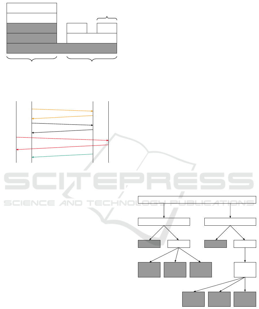
The communication model is divided into three
layers, as shown in Figure 2: The transport layer, the
secure channel layer and the session layer. The trans-
port layer establishes the network connection between
client and server. The secure SecureChannel provides
a secured, long-running connection between the two
communication partners. These security features in-
clude encryption and integrity checking, and are de-
fined by a security policy. The Session contains the
application-layer connection between two OPC UA
services and can only be accessed via a single Se-
cureChannel. Sessions are stateful and contain, for
example, linked authentication information like user
credentials. However, sessions are ultimately inde-
pendent from the underlying communication proto-
col, making it possible to transfer a session to another
SecureChannel.
OPC UA Client OPC UA Server
Communication Stack
Session Stack
Communication Stack
Session Stack
SecureChannel
Session
Transport
Figure 2: The OPC UA communication stack, adapted from
(OPC Foundation, 2017a, 20).
OPC UA has its own type system that is used to
send packets over the network. The corresponding
standard differentiates between simple and structured
data types (OPC Foundation, 2017b, 35).
Some data types that need to be implemented ma-
nually are called built-in data types. The simple data
types are subtypes of these built-in data types. They
cannot be differentiated from another when encoded
(OPC Foundation, 2017b, 35). These data types form
the base from which all other data types can be ge-
nerated (OPC Foundation, 2017c, 6). Parsing beha-
vior for built-in data types is specified in the standard
(OPC Foundation, 2017c, 6) and is fixed unless the
standard is changed. Among other things, the built-
in data types contain so called Variants and Exten-
sionObjects (OPC Foundation, 2017c, 6). Variants
can contain other built-in data types or arrays of ot-
her built-in data types. The length of the contained
array is represented by a length field in the Variant
(OPC Foundation, 2017c, 16). In contrast, Extensi-
onObjects are used to transmit an arbitrary data type
over the network. The sent data type is modeled in the
server’s address space. In order to achieve this, the
ExtensionObject contains the encoded data and the id
of the data type that was used to encode the data (OPC
Foundation, 2017c, 15).
Structured data types are modeled in a server’s
address space, where they can be retrieved in order
to parse incoming traffic (OPC Foundation, 2017b,
35). These data types represent an aggregation of
other structured data types and/or simple data types
(OPC Foundation, 2017b, 69). When these data ty-
pes are sent over the network, the receiving end needs
to know how to parse them. This is achieved by en-
capsulating them in the aforementioned ExtensionOb-
jects. The receiving end can retrieve the parsing rules
with the information in the ExtensionObject for the
encapsulated type from the server in order to parse
the type (OPC Foundation, 2017b, 35).
Data types can be specified via XML schema fi-
les, which can be parsed by OPC UA applications.
Commonly known data types can be found in a pu-
blicly available schema file, so that they do not have
to be read from a server each time (OPC Foundation,
2017b, 35).
Due to the way OPC UA enables arbitrary mo-
deling of data types, it is possible to define a type that
contains itself directly or indirectly through another
type.
3.2.2 Profinet IO
Profinet IO (PNIO) is a real-time enabled industrial
Ethernet standard defined in IEC 61158-6-10. Accor-
ding to a study from 2017 (compared to 2016)(HMS
Industrial Networks, 2017), industrial Ethernet has a
market share of 46% (38%) in IACS, whereas clas-
sic field buses have 48% (58%). 6% (4%) of the sold
Design of an Example Network Protocol for Security Tests Targeting Industrial Automation Systems
731
Ethernet
IP
UDP
DCE/RPC
PNIO-CM
PNIO-RT
PNIO-AL DCP
Connection
Establishment
Cyclic
Communication
Connection
Establishment
Figure 3: Protocol stack of PNIO.
PNIO Master
IP
MAC
PNIO Client
IP
MAC
DCP IdentReq D
Name
DCP IdentOk D
Name
ARP “Who has?”
ARP “Is at ...!”
CM ConnReq
CM ConnResp
RT
Figure 4: Begin of the regular startup process of a PNIO
network with a PNIO master and a PNIO client until the
first RT packet, from (Pfrang and Meier, 2018).
communication devices use wireless protocols. Sie-
mens selling the Profibus family is the market leader
in Europe and China.
As depicted in Figure 3, the PNIO protocol stack
is based on Ethernet. For establishing a connection, it
uses both DCP (discovery and configuration protocol)
and PNIO-CM (configuration management). DCP is
based on PNIO-RT (real-time), whereas PNIO-CM
makes use of IP, UDP and DCE/RPC. In a nutshell,
PNIO communication is set up with different proto-
cols using different protocol stacks.
The interaction between the different protocols is
shown as a sequence diagram in Figure 4. A cha-
racteristic of PNIO-CM is that the type of a PNIO-
CM packet (Read, Write, Connect etc.) is defined
by a field within the underlying DCE/RPC protocol.
Within the connection establishment, the PNIO mas-
ter and PNIO client define variables and data types as
blocks which are exchanged later on as binary data.
Once a connection is established, PNIO devices trans-
fer real-time data via PNIO-RT.
While exchanging real-time data, timeouts are re-
set once a communication partner receives a valid RT
message. If the delay of a packet exceeds a configured
amount of time, RT communication is stopped and an
alarm packet is sent instead.
3.2.3 Other Protocols
DCE/RPC (Distributed Computing Environment /
Remote Procedure Calls) is the base of the PNIO-CM
protocol. It breaks with the traditional modeling of
states and transitions in network protocols as it defi-
nes a maybe flag. In a client to server communica-
tion, a client can issue a maybe request. This means
that the client does not expect a response and there-
fore cannot be sure if the server executes the request
or not.
ETSI TS 103 097 V1.2.1 (ETSI, 2015), a proto-
col for Intelligent Transport Systems, defines a packet
field as variable-length vectors with variable-length
length encoding. This means that the length itself is
encoded with a number of 1 bits according to the ad-
ditional number of octets used to encode the length,
followed by a 0 bit and the actual length value.
3.3 Packet Field Categorization
According to the analysis of both common Internet
protocols like TCP and UDP and the aforementioned
industrial protocols, a characterization of packet fields
has been performed. Figure 5 depicts a tree-based
schema how packet fields can be categorized. Grey
boxes represent leaves. A packet field consists of both
a length and a parsing rule.
Packet Field
Length Parsing Rule
Fixed Variable
Depends
on itself
Depends
on other
Field
Fixed Variable
Itself Other Field
Separate
Request
Switched or
Specified by
Separate
Request
Figure 5: Packet field categorization.
3.3.1 Length
The length can be specified with a number of bytes or
a number of bits. The latter means that fields might
not be aligned to byte borders. Usually, if there are
fields that are not a multiple of 8 bits (a byte), they are
ForSE 2019 - 3rd International Workshop on FORmal methods for Security Engineering
732

laid out (filled up with a so-called padding of zeroes).
That results in fields always starting at a byte border
if they are a multiple of a byte. It is also possible, that
the length specifies a number of fields that are present
in the packet. If that is the case, the parsing rule for
the field that is repeated, is applied as often as the
length field specifies. An example of this would be an
array of fields.
The length of a field can be either fixed or varia-
ble. An example for a fixed length field is a field that
contains an integer. The length of a variable length
field can either depend on itself or depend on other
fields or been agreed on in a separate request.
An example for a dependance on itself is if the
length field is inline, for example the number of 1
from the beginning until the first 0 depicts the length
of the field in bytes (see Section 3.2.3). In case of
a length determination from another field, for exam-
ple a separate integer length field depicts the length
of the field in bytes. If the length of a specific field
is already agreed on in the connection establishment
process, no indication of the length has to be transfer-
red in the particular packet.
3.3.2 Parsing Rule
The parsing rule defines the way the field is to be par-
sed. In case of a fixed parsing rule, it is defined in
a standard and fixed regardless the circumstances. A
variable parsing rule however requires a fixed rule
that defines how the parsing rule is to be parsed. This
fixed rule can either be switched or specified by itself,
by another field or via a separate request. If a parsing
rule is switched, this can be done using an enumera-
tion. If the parsing rule is specified, for example shell
code is transferred which has to be evaluated in order
to parse the field.
The parsing rules themselves can be distinguis-
hed between two types: Elementary types on the one
hand usually represent a value that can be stored in a
programming languages basic types, like for example
ints or floats. Compound types on the other hand re-
present a collection of other fields. These other fields
can either be of elementary or compound type.
An example for a compound type is shown in Fi-
gure 6. StringField is a compound field consisting of
a length field and a charlist field. LengthField is a an
elementary field which is parsed to an integer. It re-
presents the number of char fields that will be parsed
in the CharList. CharList is a compound field, consis-
ting of multiple char fields. Finally, CharField is an
elementary field which is parsed to a char.
Network layers according to the ISO/OSI model
can be modeled as compound types. The Ethernet
layer as a whole, for example, is a compound type
StringField -- Compound field
LengthField -- Elementary field (int)
CharList -- Compound field
CharField -- Elementary field (char)
Figure 6: String as an example for a compound type.
consisting of the source and destination MAC etc.
The payload contains a compound type that is deter-
mined by the type field. Usually the payload is parsed
according to a fixed parsing rule.
Compound types can be arranged in a way that
they allow direct or indirect recursion, which presents
a challenge for implementers. In Scapy for example,
in order to model direct recursion it is necessary to
modify an already created class. The Class has an at-
tribute that contains a list of fields. During the parsing
of the class, the class is not yet defined, so it cannot
contain a reference to itself. In order to circumvent
this restriction the class has to be modified after its
creation.
Conditional fields, i.e. fields that are only present
depending on other parts of the packet, can be repre-
sented by fields with variable parsing rules. The par-
sing rule changes depending on a switch field. If the
field is present, it is parsed according to the fields rule.
If it is not present, the parser just parses zero bytes,
i.e. skips the field.
3.4 Requirements
According to the analysis of the use cases, the com-
mon industrial protocols, and taking into account
the packet field categorization, the following requi-
rements for the example protocol are inferred. They
are split in two categories: State requirements (prefix
SR) and packet requirements (prefix PR).
SR STATE. The example protocol is a stateful net-
work communication protocol. Its states are con-
nected via transitions.
SR TRIG. Transitions are triggered either by
(a) receiving network packets or
(b) temporal conditions.
SR EFFECT. Transitions trigger one or more of the
following effects:
(a) sending network packets,
(b) starting timeouts,
(c) or no effect at all.
SR SEND. In at least one state, network packets are
being sent without any transition to another state.
SR STACK. The example protocol is based on exis-
ting protocol stacks. It uses more than one stack.
SR
INFO. The example protocol makes use of un-
derlain protocol information.
SR TIMEOUT SM. The example protocol uses more
than one timeout in one state.
Design of an Example Network Protocol for Security Tests Targeting Industrial Automation Systems
733

SR TIMEOUT MS. At least one timeout is used in
more than one state.
PR DETERM. The example protocol comprises pac-
kets that contain at least one field with each combi-
nation of length and parsing rule determination de-
picted in Figure 5.
4 DESIGN
The example protocol has to be an artificial network-
based communication protocol comprising every pe-
culiarity which can be observed in common existing
industrial communication protocols. In order to ful-
fill that demand, the requirements regarding both the
protocol behavior and the packet field definitions de-
termined in Section 3.4 have to be met.
Additionally, in order to support the use cases de-
picted in Section 3.1, the protocol has to be made pu-
blicly available. This allows security researchers for
implementing and evaluating tools and frameworks
dealing with network communication.
4.1 Protocol Behavior
The example protocol uses two layers which are stac-
ked upon TCP: A channel layer and a session layer.
Additionally, it provides regular services which can
be called in different connection states. A special ser-
vice which can be invoked only in the session layer
is exchanging RT (real-time) traffic on top of UDP.
The layers are depicted in Figure 7. This basic setup
of the example protocol fulfills the SR STATE., the
SR TRIG. (a), the SR EFFECT. (a) and the
SR STACK. requirements.
Ethernet
IP
TCP
Channel
Session
Service
RT
UDP
Service
Service
Figure 7: The example protocol stack.
A channel is dependent on a TCP connection. To
establish a channel, a TCP connection needs to be es-
tablished first. If a channel is closed, the TCP con-
nection remains active and can be reused. A session
may only be established on an existing channel but
can persist even if the channel is closed. To reuse an
existing session, it needs to be attached to a new chan-
nel.
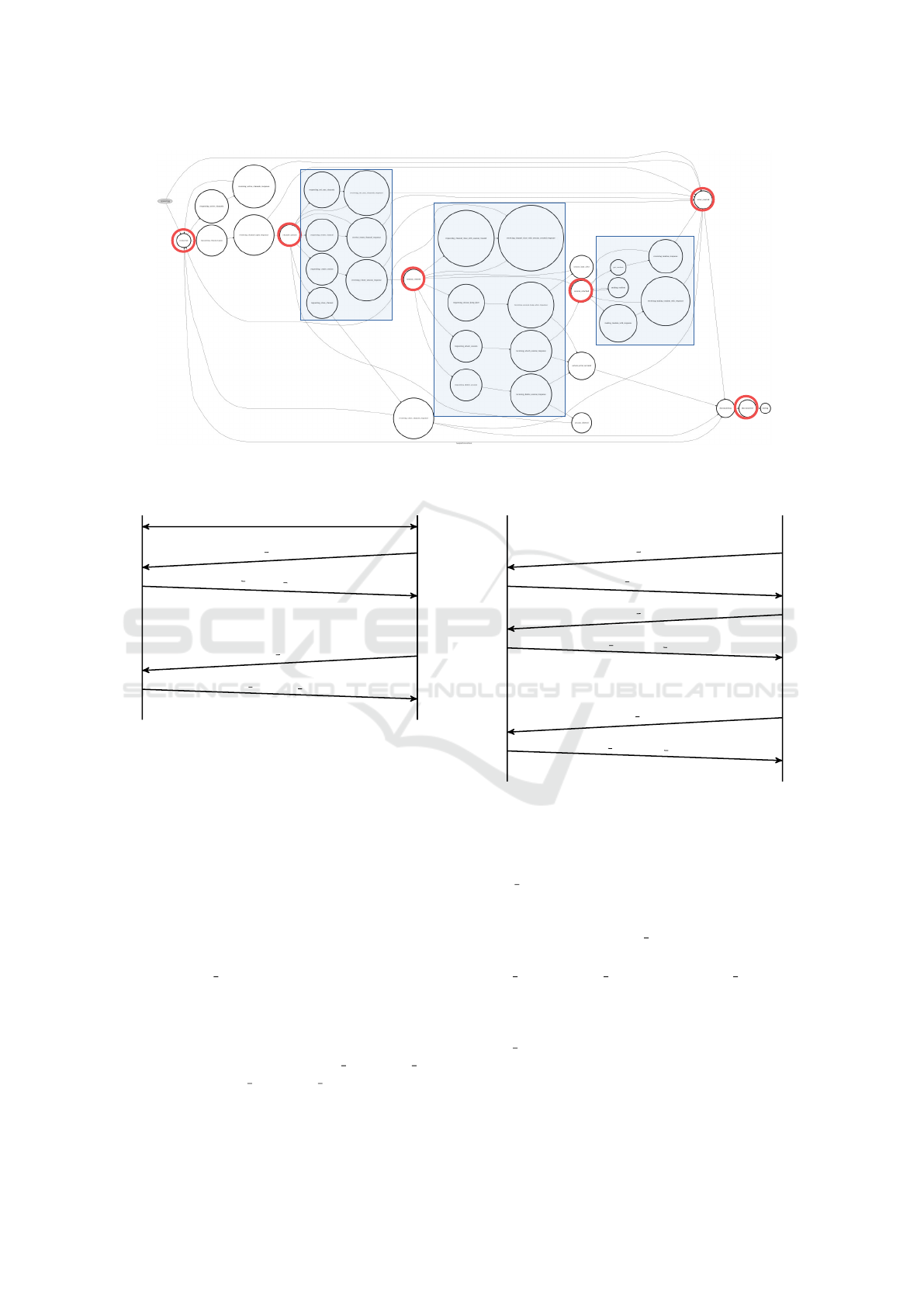
The following explanation is intended to be an
overview over the features of the example protocol
and by no means a full protocol description. To show
the complexity, Figure 8 pictures a state machine
graph of the example protocol. States are depicted
as circles, transitions as arrows. While the actual na-
mes of the states are not readable, special connection-
related states are highlighted: Connected (CON),
Channel opened (OPE), Session created(CRE), Ses-
sion attached (ATT), Disconnected (DIS) and Error
(ERR). Additionally, accumulations of states respon-
sible for providing the services, are marked using blue
boxes.
4.1.1 Channel Layer
As can be seen in Figure 7, the channel layer is built
upon TCP. The establishment of a channel is depicted
in Figure 9. To establish a new channel, first a TCP
connection is established using a three-way hands-
hake.
When the TCP connection is established, the
client sends a CHANNEL OPEN request to the ser-
ver. The client may define a timeout after which
the establishment of the channel is canceled. The
server sends either a CHANNEL OPEN RESPONSE
or an ERROR response. These timeout defini-
tion fulfills the requirements SR TRIG. (b) and
SR EFFECT. (b).
Each message sent on a channel has a sequence
number which is incremented with each package sent.
The sequence number used by the client might be dif-
ferent to the sequence number of the server.
Each channel has an ID. With this, it is possible
to manage more than one channel at a time. This ID
needs to be transferred with each message sent on the
channel. Using the corresponding channel service, it
is possible to set the maximum number of channels
that can be open in parallel. Channel services can be
issued by the client with a NOACK flag. If set, the ser-
ver will perform the action associated with the request
but will not send any response packet. This fulfills the
SR EFFECT. (c) and SR SEND. requirements.
An active channel may be closed either by the ser-
ver or the client using CHANNEL CLOSE. With a
different request, it is also possible to renew the se-
quence numbers used. The underlain TCP connection
will stay alive allowing for both executing services or
creating a new channel.
The example protocol defines a service which pro-
vides the possibility to find out the number of cur-
rently active channels (get active channels). It is pos-
sible to define a timeout for this request. After this
ForSE 2019 - 3rd International Workshop on FORmal methods for Security Engineering
734
CON
OPE
CRE
ATT
DIS
ERR
Figure 8: The state machine of the example protocol.
Server Client
TCP Handshake
CHANNEL OPEN(timeout)
CHANNEL OPEN RESPONSE(ID)
.
.
.
CHANNEL CLOSE(ID)
CHANNEL CLOSE RESPONSE
Figure 9: Channel handshake of the example protocol.
time runs out, a response to the request is no longer
processed.
4.1.2 Session Layer
As has been described before, a session is built upon
a channel but may persist after the channel is closed.
The establishment of a session is pictured in Figure
10.
For this, an existing TCP connection and an ex-
isting channel is required. First, a session is created
using SESSION CREATE. An optional timeout may
be sent with this request. The timeout indicates the
time-to-live of the session after the last package has
been sent. With this, it is possible for the session
to persist if a connection is aborted. The persistence
of the session timeout fulfills the SR TIMEOUT MS.
requirement. The SR TIMEOUT SM. requirement is
fulfilled as well since there exists additionally the ti-
meout of the TCP connection.
Server Client
SESSION CREATE(ttl)
SESSION RESPONSE(ID)
SESSION ATTACH(ID)
SESSION ATTACH RESPONSE
.
.
.
SESSION DELETE(ID)
SESSION DELETE RESPONSE
Figure 10: Session handshake of the example protocol.
After the creation of the session, it is necessary
to attach it to an existing channel. For this, SES-
SION ATTACH needs to be requested. This message
includes the ID of the session that will be attached to
the channel the message is sent over. A session may
be deleted using SESSION DELETE.
The session layer defines three services:
make random, get random and send RT. These
services may only be used if an active session is
established. This is only the case if the session is
attached to the currently active channel. In short,
make random creates a random number and stores
it on the server. Similar to the channel service, it
provides a NOACK bit flag. If this flag is set, no
response is sent. The random number may be sent
back directly in a response or might be requested
Design of an Example Network Protocol for Security Tests Targeting Industrial Automation Systems
735

TCP
IsuProtoHeader
IsuProtoServices
IsuProtoChannelHeader
IsuProtoServices
IsuProtoSessionHeader
IsuProtoServices
Figure 11: Layering of example protocol packets.
through get random. This decision needs to be sent
with the request. send RT starts exchanging RT
packets via UDP with a configurable speed.
4.2 Packet Structures
The packet structure of the example proto-
col follows the layering depicted in Figure
11. An IsuProtoHeader can either con-
tain an IsuProtoService message or an
IsuProtoChannelHeader. The same goes for
the layers nested deeper with additional headers.
The determination which layer follows is done via
a type field which fulfills SR INFO.. Each service
has a request message and a response message. The
services are used to model the protocol behavior.
To fulfill the PR DETERM. requirements, some
custom fields were added and included in at least one
service packet. These special fields are explained in
the following.
The BitField is a field with fixed length and a
fixed parsing rule. It can have a (fixed) length speci-
fied in bits.
The fixed length with a parsing rule switched by
another field is modeled implicitly by using the lay-
ering in the example protocol. The specified type in
the IsuProtoHeader determines whether the following
bytes have to be interpreted as IsuProtoServices or
as IsuProtoChannelHeader (see Figure 11).
FixedLengthVariableRuleFields contain bi-
nary data. The parsing rules that specify how
that data is to be parsed and encoded can be sent
with the packet, or be supplied separately, be-
cause they have been requested beforehand. A
FixedLengthVariableRuleField needs a parsing
and encoding rule, that specifies how the data is par-
sed and encoded respectively. For the example proto-
col, any arbitrary Python code is allowed. The length
of the data is not specified and the parsing rule needs
to decide when to stop parsing.
The ByteListField has a fixed parsing rule. The
field consists of multiple bytes that comprise a list of
bytes. The length of this list is specified in an external
field in the packet.
SwitchedArrays are arrays that can contain a
specified set of other fields that are switched by a type
field. The type field determines the type of all the con-
tained fields. The number of fields is determined by a
length field.
DynamicLengthVariableRuleFields
have the same functionality as
FixedLengthVariableRuleFields except that
the length of the data that contains the value is
specified by another field, and not fixed.
VariableLengthLengthFields are similar to
variable-length vectors with variable-length length
encoding fields from ITS (see Section 3.2). The length
of the field in bytes is determined by a sequence of
ones at the beginning of the field, followed by a zero.
The remaining bits comprise the value of the field.
The TerminatorStringField models a byte
string that is terminated by a specific byte. The byte
that terminates the string is specified in a separate
field. Because the string is parsed until the terminator
byte is encountered, the field can be categorized as a
field whose length depends on its own data.
VariableRuleFields contain binary data. The
parsing rules that specify how that data is to be par-
sed and encoded can be sent with the packet, or be
supplied separately, because they have been requested
beforehand. A VariableRuleField needs a parsing
and encoding rule, that specify how the data is parsed
and encoded respectively. For the example protocol,
any arbitrary Python code is allowed. The length of
the data is not specified and the parsing rule needs to
decide when to stop parsing. It follows, that the length
depends on the fields own data, and the parsing rule is
variable.
5 CASE STUDY
The example protocol comprises the specification, a
prototypical implementation using Python and Scapy
as well as several packet captures of the client server
communication. It is available online on GitHub.
In order to illustrate the usefulness of the example
protocol, the protocol learning use case described in
Section 3.1 will be applied in the following.
5.1 Scenario
There exist different tools for network protocol lear-
ning. Netzob (Bossert and Guih
´
ery, 2012) infers both
a vocabulary (packet structures) and a grammar (pro-
tocol behavior) from a given network communication.
NEMESYS (Kleber et al., 2018), a newer approach,
focuses on inferring packet structures from network
messages of binary protocols. All tools accept as in-
put packet captures (PCAP). As output, they provide
ForSE 2019 - 3rd International Workshop on FORmal methods for Security Engineering
736

different kinds of results which represent the inferred
protocol behavior and packet structures.
5.2 Example Protocol Usage
Network communication comprising the example
protocol can be generated by starting both a server
and a client running the prototypical implementation.
Packet captures can be recorded locally on either the
server or the client running tcpdump.
The listing in Figure 12 presents the example com-
munication of a client which first opens a connection
to the server, retrieves 100 random numbers and clo-
ses the connection finally. In line 2, the TCP con-
nection is set up. Line 3 creates a channel, line 4 a
session. The session id is extracted in line 5 from the
response packet which is used for attaching the ses-
sion in line 6. In the lines 7 and 8, the get random()
service is being used for 100 times. Line 9 deletes the
session, line 10 closes the channel and line 11 discon-
nects from the server.
1 c = Client()
2 c.connect()
3 c.create_channel()
4 p = c.create_session("My Session")
5 session_id = p[SessionCreateResp].id
6 c.attach_session(session_id)
7 for i in range(0, 100):
8 c.get_random(session_id=session_id)
9 c.delete_session(session_id)
10 c.close_channel()
11 c.disconnect()
Figure 12: Example client source code for connecting to a
server using the example protocol.
The resulting PCAP file consists of 218 network
packets. While 2 times 100 contain the random num-
ber requests and responses, 11 are used to setup the
communication and 7 for their termination.
5.3 Discussion
NEMESYS compares the results of the inferred pac-
ket structure with the real packet structure extracted
via tshark from Wireshark dissectors. As long as no
Wireshark dissector for the example protocol exists,
the needed structures for this comparison have to be
written manually. Besides that issue, the prototypi-
cal implementation of the example protocol provides
a useful basis for training and the development of pro-
tocol learning tools dealing with both packet structu-
res and protocol behavior.
6 CONCLUSION
The design and publication of an example protocol
is a big advantage for the security testing domain in
IACS. Recent work in the creation of tools for dealing
with arbitrary network protocols suffered from mis-
sing complete knowledge about possibilities for both
packet structures and protocol behavior. With the ex-
ample protocol in mind, tool developers can improve
their tools accordingly.
In the case of protocol learning, tools can be
improved regarding their ability to recognize packet
fields. The variety of length and parsing rule determi-
nation described in the analysis is realized in the ex-
ample protocol prototypical client server implemen-
tation.
Future work includes implementing a Wireshark
dissector for the example protocol in order to allow
for automatic success verification of protocol learning
tools. Additionally, the design of a meta model for
the description of network protocols which covers all
the observed peculiarities in the example protocol is a
great challenge. Applying this meta model approach
to the example protocol, a machine-readable defini-
tion of the example protocol can be given.
Last but not least, packet crafting and processing
tools have to be improved or re-implemented by scra-
tch taking into account the results of this research.
ACKNOWLEDGEMENTS
We thank Andreas Fleig for ideas on requirements for
the example protocol and Mario Kaufmann for assis-
tance at implementing the example protocol.
This work was supported by the German Federal
Ministry of Education and Research within the frame-
work of the project KASTEL SKI in the Competence
Center for Applied Security Technology (KASTEL).
REFERENCES
Biondi, P. (2018). Scapy: Packet crafting for python2 and
python3. https://scapy.net/. [Online; accessed 2018-
12-23].
Bossert, G. and Guih
´
ery, F. (2012). Security evaluation of
communication protocols in common criteria. In Proc
of IEEE International Conference on Communicati-
ons.
Braden, R. (1989). Rfc-1122: Requirements for internet
hosts. Request for Comments, pages 356–363.
Duchene, J., Le Guernic, C., Alata, E., Nicomette, V., and
Ka
ˆ
aniche, M. (2018). State of the art of network pro-
Design of an Example Network Protocol for Security Tests Targeting Industrial Automation Systems
737

tocol reverse engineering tools. Journal of Computer
Virology and Hacking Techniques, 14(1):53–68.
ETSI (2015). ETSI TS 103 097: Intelligent Transport Sys-
tems (ITS). ETSI, v 1.2.1 edition.
Felderer, M., B
¨
uchler, M., Johns, M., Brucker, A. D., Breu,
R., and Pretschner, A. (2016). Security testing: A sur-
vey. In Advances in Computers, volume 101, pages
1–51. Elsevier.
HMS Industrial Networks (2017). Variantenvielfalt bei
Kommunikationssystemen. https://www.feldbusse.de/
Trends/trends.shtml. [Online; accessed 17-December-
2018].
ISO (1994). ISO/IEC 7498-1:1994 - Information techno-
logy – Open Systems Interconnection – Basic Refe-
rence Model: The Basic Model. International Orga-
nization for Standardization (ISO), Geneva, Switzer-
land.
Kleber, S., Kopp, H., and Kargl, F. (2018). NEMESYS:
Network message syntax reverse engineering by ana-
lysis of the intrinsic structure of individual messages.
In 12th USENIX Workshop on Offensive Technologies
(WOOT 18), Baltimore, MD. USENIX Association.
Kurose, J. F. and Ross, K. W. (2013). Computer networ-
king: a top-down approach: international edition.
Pearson Higher Ed.
L
¨
uders, S. (2011). Stuxnet and the impact on accelera-
tor control systems. Proceedings of ICALEPCS2011,
Grenoble, France, pages 1285–1288.
OPC Foundation (2017a). OPC Unified Architecture Speci-
fication Part 1: Overview and Concepts. OPC Foun-
dation, version 1.04 edition.
OPC Foundation (2017b). OPC Unified Architecture Speci-
fication Part 3: Address Space Model. OPC Founda-
tion, version 1.04 edition.
OPC Foundation (2017c). OPC Unified Architecture Speci-
fication Part 6: Mappings. OPC Foundation, version
1.04 edition.
Peterson, L. L. and Davie, B. S. (2007). Computer net-
works: a systems approach. Elsevier.
Pfrang, S. and Meier, D. (2018). Detecting and preventing
replay attacks in industrial automation networks ope-
rated with profinet io. Journal of Computer Virology
and Hacking Techniques, 14(4):253–268.
Pfrang, S., Meier, D., Friedrich, M., and Beyerer, J. (2018).
Advancing protocol fuzzing for industrial automation
and control systems. Proceedings of the 4th Internati-
onal Conference on Information Systems Security and
Privacy (ICISSP 2018), pages 570–580.
Potter, B. and McGraw, G. (2004). Software security tes-
ting. IEEE Security & Privacy, 2(5):81–85.
ForSE 2019 - 3rd International Workshop on FORmal methods for Security Engineering
738
