
FUSE: A Microservice Approach to Cross-domain Federation using
Docker Containers
Tom Goethals
a
, Dwight Kerkhove, Laurens Van Hoye
b
, Merlijn Sebrechts
c
,
Filip De Turck
d
and Bruno Volckaert
e
Department of Information Technology, Ghent University - imec, IDLab,
Technologiepark-Zwijnaarde 126, 9052 Gent, Belgium
Keywords:
Collaboration, Unified Services, Microservices, Federation, Containers.
Abstract:
In crisis situations, it is important to be able to quickly gather information from various sources to form
a complete and accurate picture of the situation. However, the different policies of participating companies
often make it difficult to connect their information sources quickly, or to allow software to be deployed on their
networks in a uniform way. The difficulty in deploying software is exacerbated by the fact that companies often
use different software platforms in their existing networks. In this paper, Flexible federated Unified Service
Environment (FUSE) is presented as a solution for joining multiple domains into a microservice based ad
hoc federation, and for deploying and managing container-based software on the devices of a federation. The
resource requirements for setting up a FUSE federation are examined, and a video streaming application is
deployed to demonstrate the performance of software deployed on an example federation. The results show
that FUSE can be deployed in 10 minutes or less, and that it can support multiple video streams under normal
network conditions, making it a viable solution for the problem of quick and easy cross-domain federation.
1 INTRODUCTION
In crisis situations, a crisis center is usually formed
which monitors the situation and takes suitable ac-
tions. It is important that crisis centers are able to
quickly gather information from various sources, for
example closed-circuit television (CCTV) or posi-
tional data, to get a complete and accurate overview of
the situation. When the required information sources
are owned by different companies, it is difficult for
the crisis center to gain access to them or to interact
with them uniformly. Fig. 1 illustrates the concept
of joining companies and a crisis center into a single
virtual network, from now on referred to as a feder-
ation. Company A joins the federation, making its
IP cameras available for use by routing their streams,
and company B allows the use of both its servers and
sensory hardware. The crisis center gathers informa-
tion from the exposed devices of both companies and
a
https://orcid.org/0000-0002-1332-2290
b
https://orcid.org/0000-0003-1192-4631
c
https://orcid.org/0000-0002-4093-7338
d
https://orcid.org/0000-0003-4824-1199
e
https://orcid.org/0000-0003-0575-5894
transforms it into a dashboard for its operators. To
do this, a federation service environment is required
which supports a wide range of operating systems and
devices. Since containers are widely supported and
easy to deploy, a container-based service environment
is preferable.
In addition to varying devices and software plat-
forms, companies participating in a federation often
have different network and security policies, making
it difficult to connect them quickly or to deploy soft-
ware in their networks (domains) in a uniform way.
Any solution to connect multiple domains should en-
sure that every company can choose exactly which re-
sources it makes available to the federation, and that
all communication between federated devices is se-
cure. Only devices that are part of the federation must
be visible from other domains, while devices from
each domain that are not part of the federation should
only be reachable from federated devices in the same
domain. For example, in Fig. 1 the data storage of
company B can be used by federation components de-
ployed in its own domain, but it is unavailable to the
rest of the federation. The same is true for the non-
federated device at company A, which is invisible to
the devices of company B and the crisis center.
90
Goethals, T., Kerkhove, D., Van Hoye, L., Sebrechts, M., De Turck, F. and Volckaert, B.
FUSE: A Microservice Approach to Cross-domain Federation using Docker Containers.
DOI: 10.5220/0007706000900099
In Proceedings of the 9th International Conference on Cloud Computing and Services Science (CLOSER 2019), pages 90-99
ISBN: 978-989-758-365-0
Copyright
c
2019 by SCITEPRESS – Science and Technology Publications, Lda. All rights reserved

Apart from being cross-domain and ensuring se-
cure communications, a federation service environ-
ment focused on crisis situations must also be fast
and easy to set up. Joining a federation should only
take minutes, with minimal intervention from com-
pany administrators. Additionally, a company should
be able to join or leave a federation at any time with-
out destabilizing the federation, and after leaving a
federation no trace of the federation service environ-
ment should be left on a company’s devices. Further-
more, the components of a federation service environ-
ment should not interfere with other processes on a
device, which means that the entire federation service
environment and all its components should be isolated
as much as possible.
The challenges for building a federation service
environment using containers can thus be summarized
as follows:
1. Enabling and securing fast cross-domain commu-
nication while restricting access to non-federated
resources
2. Isolating the federation service environment from
other software
3. Ensuring fast and easy deployment of the federa-
tion service environment on a large range of de-
vices
This paper presents Flexible federated Unified
Service Environment (FUSE) to tackle these chal-
lenges. FUSE provides a microservice-oriented,
container-based service environment to deploy and
manage software on federated domains. It is designed
to quickly set up ad hoc federations with minimal
intervention, ensures secure communication between
domains and prevents non-federated devices from be-
ing visible from other domains.
Section II presents related work to the challenges
presented in this introduction, and Section III de-
scribes how they are solved in FUSE. Section IV de-
scribes the test setup for a basic FUSE federation,
while section V details the system requirements of
FUSE and presents performance results for a typical
use case. Section VI discusses the results and appli-
cations of FUSE, and suggests some topics for future
work. Finally, section VII concludes the paper.
2 RELATED WORK
Previous federation service environment projects
have resulted in frameworks such as Fed4Fire
(Wauters et al., 2014), Beacon (Moreno-Vozmediano
et al., 2016) and FedUp! (Bottoni et al., 2016).
Figure 1: Example federation.
Fed4Fire has a different use case from FUSE and re-
quires the implementation of an API to integrate de-
vices into a federation, which makes it inadequate
for the rapid ad hoc use cases of FUSE. BEACON
is focused on cloud federation and security as a func-
tion of cloud federation, but the use case of FUSE
requires it to work in company networks and around
existing and unchangeable security policies. FedUp!
is a cloud federation framework focused on improv-
ing the setup time for heterogenous cloud federations.
Unlike previously mentioned frameworks, FUSE op-
erates on company networks rather than cloud infras-
tructure and aims to cut down set-up time to minutes
or less with minimal intervention from system admin-
istrators, independent of target devices and operating
systems. Many tools have been created for the dif-
ferent aspects of federation, for example jFed (Ver-
meulen et al., 2014) (general lifecycle management),
OML
1
(measurement and monitoring) and OpenID
(Recordon and Reed, 2006) (trust, user authentica-
tion). Each of these tools only solves part of the prob-
lem FUSE faces and often requires the implementa-
tion of specific APIs to work with. For example jFed,
which was developed for the Fed4Fire project, pro-
vides high-level control over federated resources, but
it only works with known hardware types and pools
of pre-configured resources.
Container engines such as Docker
2
and rkt
3
have
been studied and evaluated extensively in literature
(Cailliau et al., 2016), for example in performance
reviews (Felter et al., 2015) and in overviews of vir-
tualization technology (Bernstein, 2014). Similarly,
the capabilities of container orchestration tools such
as Kubernetes
4
and its precursor Borg are explored
in various studies (Verma et al., 2015; Casalicchio,
2017). Microservice architectures using containers
have seen a lot of attention, specifically for their use
1
https://wiki.confine-project.eu/oml:start
2
https://www.docker.com/
3
https://coreos.com/rkt/
4
https://kubernetes.io/
FUSE: A Microservice Approach to Cross-domain Federation using Docker Containers
91

in rapid and easy deployment of (cloud) applications
(Kratzke, 2017; Amaral et al., 2015). However, Ku-
bernetes by itself is insufficient to build a federation
service environment when the devices in the federa-
tion are hidden from public view by firewalls or by
other means, which is often the case in company net-
works.
Docker security has been thoroughly studied (Bui,
2015), and there are security best practices for Kuber-
netes (Kubernetes, 2016). However, no work is found
on securing network traffic specifically, which is re-
quired when sending valuable data between domains
over the internet. Kubernetes is capable of forming
federations of multiple Kubernetes clusters (Kuber-
netes, 2018), but to the best of our knowledge, no
work has been done on a single Kubernetes cluster
spanning multiple physical domains.
Certain studies investigate the usefulness of edge
computing and edge offloading (Shi and Dustdar,
2016; Samie et al., 2016), two concepts whereby
computing workload is moved from cloud hardware
to edge devices (or vice versa) based on hardware
load and service demand. Of particular interest are
studies where virtualization is employed for edge of-
floading purposes (Morabito et al., 2018). This work
is closely related to how and why federations could
include edge devices to serve as information sources
or processing hardware.
Various aspects of cloud resource management
have been studied (Jennings and Stadler, 2015), for
example the scalability of certain topologies. Stud-
ied topologies include a centralized controller (Atrey
et al., 2016), management hierarchies (Whaiduzza-
man et al., 2014; Wang and Su, 2015) and fully dis-
tributed approaches (Miraftabzadeh et al., 2017).
3 COMPONENTS AND
ARCHITECTURE
Within a single domain, a federation can easily be
formed using Docker containers and Kubernetes. The
use of Docker containers ensures that software can be
deployed to a wide variety of target devices, as long as
they support Docker. Kubernetes is used to join and
manage all the devices in the federation, and to deploy
software on those devices. The only downside to this
approach is that software needs to be containerized in
order to deploy it.
Kubernetes identifies the roles of specific devices
in a cluster by making them either a master or a
worker node. FUSE, being built around Kubernetes,
adopts these two roles while giving them additional
responsibilities. Master nodes are the equivalent
of Kubernetes masters and consist of a Kubernetes
control plane and other services required for FUSE.
Worker nodes perform the function of Kubernetes
workers and generally only contain a kube-proxy and
deployed containers.
The rest of this section details how FUSE solves
the problems posed in the introduction and describes
how they fit into the basic Docker and Kubernetes
setup described here.
3.1 Cross-domain Federation and
Security
Kubernetes deploys containers in groups called pods,
which have their own virtual network for communi-
cation between all devices that constitute a cluster.
This inter-pod communication is done with the aid of
a Container Network Interface (CNI) driver
5
, such as
Flannel
6
, which assigns an IP address from a config-
urable range to every pod running on the Kubernetes
nodes under its control. However, Flannel runs into
problems when a Kubernetes node is unreachable, for
example when it is hidden behind a firewall or when
no route to the target machine exists. Kubernetes, be-
ing primarily built for cloud environments, has no fa-
cilities to work around this problem.
In order to enable Flannel traffic between do-
mains, and to secure that traffic, OpenVPN tunnels
7
are created between FUSE worker nodes and the mas-
ter node. Every FUSE master node runs an OpenVPN
server, while all FUSE nodes (including the master)
have an OpenVPN client that connects to the VPN
server on the master node. Once a connection is es-
tablished, a FUSE node gets an IP address from a
configurable range of VPN addresses. This address
is added to routing tables in FUSE services, together
with the Flannel address range of a node. After this
initial setup, all of the ports on a node’s OpenVPN
interface are forwarded to Flannel. To optimize per-
formance, Flannel is run using the host-gw
8
back-end
instead of vxlan, which puts pod network packets di-
rectly on the OpenVPN interface instead of encapsu-
lating them. The downside of using only one Open-
VPN server, running on the master node, is that all
traffic is routed via the master node, even if it is just
between worker nodes.
Apart from enabling cross-domain federation and
securing communications, FUSE also needs to en-
5
https://kubernetes.io/docs/concepts/extend-
kubernetes/compute-storage-net/network-plugins/
6
https://github.com/coreos/flannel
7
https://openvpn.net/
8
https://github.com/coreos/flannel/blob/master/
Documentation/backends.md
CLOSER 2019 - 9th International Conference on Cloud Computing and Services Science
92
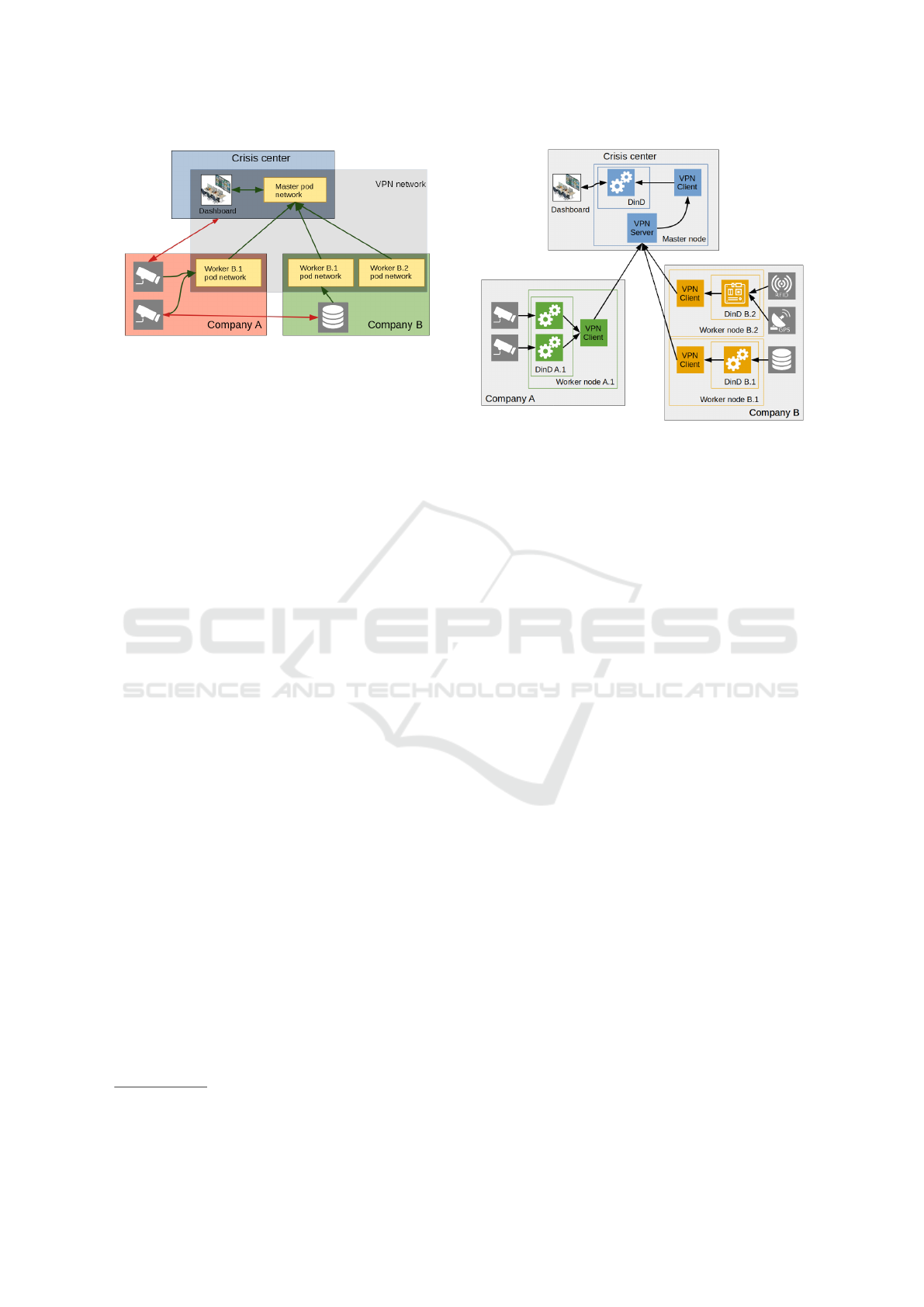
Figure 2: High-level network overview of an example
FUSE federation.
sure that non-federated devices can not be reached
from a domain other than the one they are in. This
is achieved by generating specific routing rules for
each node in a federation. The concept is shown in
Fig. 2, where a red, green or blue box represents a
company network (domain), yellow boxes represent
the distributed parts of the Kubernetes pod network
and the gray translucent box represents the VPN net-
work which connects all FUSE nodes. Green arrows
indicate which devices can interact with each other,
while red ones show which ones can not. In company
A, worker B.1 can receive camera streams from non-
federated devices in company A through its company-
assigned IP address, and it is also able to forward
the stream to the crisis center over its FUSE VPN-
assigned IP address. However, non-federated devices
in company A can not be reached by any devices from
either the crisis center or company B. This approach
solves the first challenge posed in the introduction.
3.2 Encapsulation
To tackle the second challenge discussed in the in-
troduction, a solution is needed that isolates FUSE
components and minimizes the required software to
deploy FUSE. All services deployed on a FUSE
worker node are containerized, but the components
of FUSE should be isolated as well. Docker-in-
Docker (DinD
9
) enables the nesting of Docker envi-
ronments by deploying a containerized Docker envi-
ronment within another Docker environment. Using
a DinD approach, FUSE components and services are
deployed in the outer docker environment, while the
inner environment runs containers deployed on the
node by Kubernetes. Thus, FUSE processes remain
isolated from other processes and a Docker installa-
tion is the only requirement to start a FUSE node. Ad-
9
https://github.com/kubernetes-sigs/kubeadm-dind-
cluster
Figure 3: Nodes and information flow of an example FUSE
federation.
ditionally, FUSE can ensure that none of its compo-
nents remain on a device after it leaves the federation.
However, both FUSE components and client software
must be containerized in order for this approach to
work. For OpenVPN, this means using an OpenVPN
server container on the master node and OpenVPN
client sidecars (Burns, 2018) on the worker nodes.
Using DinD creates an additional network layer
between the host OS and the Kubernetes node. As
previously mentioned, Flannel takes care of network
traffic for the pods in the inner Docker environment,
but the outer Docker environment still needs an ad-
dressing scheme. For this layer, a static address was
chosen for each FUSE service, no matter which node
it runs on, so that a FUSE node always knows where
to reach a certain service running on it. For example,
a VPN server container IP address always ends in .2,
while a VPN client container address always ends in
.3.
Fig. 3 shows the federation illustrated in Fig. 1,
with the concepts discussed in this section. Fig. 3
shows that every node, even the master node, has a
VPN client which is connected to the master node’s
VPN server. Company A has a single worker node,
which is running multiple containers to forward video
streams to the crisis center through a single VPN
client. Company B, on the other hand, has two worker
nodes, each with their own VPN clients. Node B.1
has a single container which gives the crisis center
access to data from company B, and node B.2 gath-
ers positional data from various sources and makes it
available to the crisis center.
FUSE: A Microservice Approach to Cross-domain Federation using Docker Containers
93

Figure 4: Test setup overview.
3.3 Fast and Easy Deployment and
Teardown
The DinD solution from the previous subsection en-
ables easy deployment and teardown of FUSE. Since
all FUSE components are running in containers, only
a single startup script is needed to deploy FUSE on a
node or to remove it from a node, with any required
containers being pulled from a remote or local Docker
registry. Thus, DinD also satisfies the third require-
ment from the introduction, but tests are needed to
confirm that this solution can run on a wide range of
devices.
4 TEST SETUP
Considering the use cases of FUSE, it is important
that it can be deployed on a large range of devices and
that both master and worker nodes can quickly join
the federation when needed. These requirements are
also part of the challenges stated in the introduction,
of which the first one demands that FUSE has good
network performance, and the third one demands that
FUSE is fast to set up and tear down on a wide range
of devices.
To confirm that FUSE meets these requirements,
measurements were performed to determine memory
consumption, required hard disk space, deploy times
for nodes and network performance of the federation.
Being able to run FUSE on a Raspberry Pi 3 is set as
a concrete goal for low-end devices. All tests were
performed on the imec/IDLab Virtual Wall environ-
ment
10
using bare metal servers. Special care was
taken to ensure that the hardware of all servers was
identical for every test run. The hardware configura-
10
http://doc.ilabt.iminds.be/ilabt-documentation/
virtualwallfacility.html
tion used for every device consists of two Intel Xeon
E5620 processors clocked at 2.4 GHz, 12GiB DDR3
memory and a 16GiB partition on a 160GiB WDC
WD1600AAJS-0 hard drive.
Fig. 4 shows the test setup. The fuse master and
worker nodes are connected by a VLAN which al-
lows setting specific amounts of packet loss and de-
lay. Meanwhile, a client PC is connected to the FUSE
VPN and interacts with Kubernetes services via the
VPN IP address assigned to the master node. By de-
fault, the 6.0.0.x address range is used, but it is config-
urable. While the client PC is not a part of the virtual
wall environment, it is directly connected over LAN,
with a ping time of only 0.24 +- 0.01ms.
The required hard disk space for a node was mea-
sured by summing the disk usage of all the required
containers and FUSE scripts. Memory consumption
was determined by comparing available memory as
reported by the free command
11
, before and after de-
ploying FUSE. Network throughput was determined
with iperf3
12
in the DinD container on both FUSE
nodes and running it in both TCP and UDP mode.
The resulting physical traffic is thus TCP-on-TCP and
UDP-on-TCP, respectively.
To determine how quickly FUSE can set up a
federation and how quickly worker nodes can join
or leave the federation, the time command was used
to measure the duration of the relevant FUSE com-
mands. The final results were calculated from ten suc-
cessful runs of each test.
As a test of FUSE performance in a typical use
case, a container is deployed to the worker node
which simulates a camera stream by looping a 720p
video file, recorded from a security camera, to a web-
socket using ffmpeg
13
. The video has mostly static
images with little movement and is encoded at 2
Mbits/s. The frame rate of the recording is 25 frames
per second (FPS), but the output frame rate is not lim-
ited. Because the frame rate is not limited and the
video stream consists of mostly static scenery, this
is a good test of FUSE network performance. How-
ever, in real crisis situations, there would likely be
a lot of activity on camera streams, possibly influ-
encing the frame rate from one moment to the next.
Since this would be harder to quantify, the FPS test is
only meant as an indication of FUSE bandwidth. A
dashboard application container, consisting of a web
page with a Node.js
14
back-end, is deployed on the
master node. The dashboard back-end receives the
worker node’s stream via a websocket and sets up a
11
http://www.linfo.org/free.html
12
https://iperf.fr/iperf-download.php
13
https://www.ffmpeg.org/
14
https://nodejs.org/en/
CLOSER 2019 - 9th International Conference on Cloud Computing and Services Science
94

proxy websocket, which in turn sends the data to the
web page opened by the client PC. The proxy web-
socket acts as an aggregator for multiple streams, but
for the tests below only one stream was used. The
web page itself plays the video using jsmpeg
15
. The
results, measured in fps, were calculated by hooking
into jsmpeg’s render loop and calculating the average
and standard deviation over 70 seconds of streamed
video.
5 RESULTS
5.1 Hardware Requirements
Worker nodes require 529 MiB of disk space and are
small enough that they can be deployed on a Rasp-
berry Pi 3 or similar devices. However, in order to
have enough room to deploy software, several giga-
bytes of free space would be recommended. Master
nodes require 1576 MiB of disk space, which is about
three times as much as a worker node. This makes
sense, since they need to deploy all FUSE compo-
nents, a VPN server and a Kubernetes master. Consid-
ering their role as communications and management
hubs for the federation, master nodes will usually be
deployed on hardware with orders of magnitude more
free space than the required amount, so this should
not be a problem.
Concerning memory consumption, a worker node
could easily be deployed on a Raspberry Pi 3, since
it needs only about 228 MiB free memory. Master
nodes need around 851 MiB free memory, which is
almost four times more than a worker node. Again,
this is due to having to run Kubernetes and all FUSE
services. It would be very hard to deploy a master
node on hardware with 1 GiB RAM, even with an ex-
tremely slimmed down host OS.
5.2 Federation Setup and Teardown
Since master nodes can be started up front and kept
ready-to-go, their start times are less important than
those of worker nodes. They have no interaction with
any other devices while deploying, so no special cases
need to be examined.
Table 1 shows the minimum, median and maxi-
mum observed times it takes to set up a FUSE master
node or tear it down. A master node takes only about
6 to 6.5 minutes to set up from scratch, while it can
be removed from a device in about 8 to 9 seconds.
15
https://github.com/phoboslab/jsmpeg
Table 1: FUSE master node create and leave times.
Create Leave
Min time (s) 356 7.87
Median time (s) 374 7.90
Max time (s) 381 8.90
For worker nodes, the quality of the network con-
nection to the master node is important for federation
setup and tear down. To examine the impact of the
connection quality, a range of combinations of com-
munication delay and packet loss were simulated. De-
lay ranges from 0ms to 400ms in 100ms steps, while
packet loss ranges from 0% to 20% in 5% steps.
Considering all the network layers in the FUSE ar-
chitecture, it is hard to model performance using ex-
isting research. FUSE traffic consists of TCP or UDP
packets from containers wrapped in TCP packets by
OpenVPN. A worker attempting to join a federation
performs a number of requests. The execution time of
a single request over TCP is
t
op
= (w
s
+
w
v
(d
v
+ d
s
)
1 − l
) (1)
where l is packet loss, d
v
is network delay, d
s
is
delay resulting from handling network operations in
software, w
s
is work not influenced by network activ-
ity (for example, parsing JSON response data), and
w
v
represents work that depends on network perfor-
mance.
However, this only works for a single request. A
federation operation, for example joining a federa-
tion, requires several calls to web services. This intro-
duces another factor caused by service call timeouts,
which in turn can cause a retry of the entire operation:
t
total
=
t
op
(1 − max(min(
d
v
−d
l
d
c
−d
l
, 1), 0))(1 − l)
(2)
Where d
l
is the delay threshold below which no
operation should time out and d
c
is the critical de-
lay threshold above which every operation results in a
timeout. For this equation, delay is in the denomina-
tor because its effect is no longer linear. The constants
in Eq. 1 and Eq. 2 have to be determined empirically
and are different for every hardware setup, but with
the results in Fig. 5 the most important effects on the
test setup can be identified.
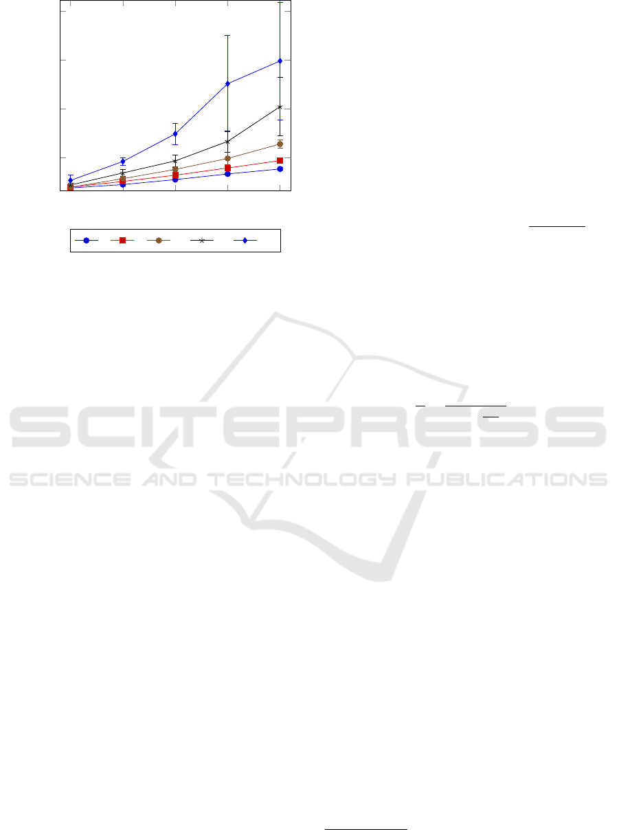
Fig. 5 shows the time it takes to join a federation
for several combinations of delay and packet loss. In
case of smooth network performance, meaning less
than 100ms delay or less than 10% packet loss, join-
ing a federation only takes as much as 1 to 4 minutes.
As the model predicts, packet loss has a strong hyper-
bolic effect on the time it takes to join a federation, but
FUSE: A Microservice Approach to Cross-domain Federation using Docker Containers
95
0 100 200 300 400
200
400
600
800
Delay (ms)
Join time (s)
0 5 10 15 20
Figure 5: Federation join time for increasing delay at sev-
eral percentages of packet loss.
it is still doable even with high rates of packet loss and
high delay. Delay has a mostly linear effect, as shown
by Eq. 1. Only for combinations of high delay and
a lot of packet loss does it turn to a slight hyperbolic
effect, explained by its term in Eq. 2. Further model-
ing is unreliable because of the large error margins on
these data points. Eventually, around 20% packet loss
and 400ms delay joining becomes so slow and erratic
that it is unlikely to still be practical. The error margin
on this data point shows that join attempts may take
anywhere from 6 to 14 minutes.
5.3 FUSE Network Performance
Fig. 6 shows the communication speed between a
FUSE master node and a worker node with packet
loss and delay set to zero. While TCP performance
is only 109 Mbits/s, the test setup has no support
for hardware encryption using the AES-NI instruction
set, which would give much better results (OpenVPN,
2018). UDP performance is very low with only 11.7
Mbits/s, meaning any FUSE traffic should be kept to
TCP as much as possible. During the tests, OpenVPN
used between 60% and 100% of a single CPU core.
Since OpenVPN runs on a single thread, these results
are about as good as they can get without optimiza-
tions. This means that communication alone takes a
large part of the total processing power of a node.
For the video streaming test, the delay between
the FUSE nodes was set from 0 to 100ms in steps of
25ms, while the effect of packet loss was examined
for 0%, 0.2%, 1% and 2%. Because the software in-
volved in this test does not use buffering, the results
are a good reflection of network performance.
Since a TCP video stream is one-way traffic that
requires no response, a different model is used to pre-
dict performance than for joining a federation. Only
packets that do not make it on the first send incur a
penalty on the rendering process. Uniform delay has
no effect on the quality of video, merely delaying the
rendering of each frame by the same amount of time,
resulting in Eq. 3 for the time to transmit and render
a frame. In this case n is the number of packets that
need to be sent for a frame, d is the network delay,
and l is the packet loss. d
0
is an intrinsic delay that
occurs from endpoint handling of network traffic and
the speed limit of electronic communication.
t
f
= d
0
n +
∞
∑
i=1
n(d + d
0
)l
i
= d
0
n −
(d + d
0
)ln
l − 1
(3)
For a d
0
that is sufficiently small compared to the
delay caused by network problems and bad connec-
tions, Eq. 3 can be reduced to Eq. 4 to estimate
FPS for video throughput. Since n can not be rea-
sonably estimated for any frame, it is replaced by t
0
,
which represents the time it takes to transmit an aver-
age frame under ideal circumstances (no packet loss,
only d
0
delay).
f =
1
t
f
≈
1
t
0
(1 −
dl
l−1
)
, d
0
d (4)
Fig. 7 shows the results of the video throughput
test, for which 24 FPS is set as the minimum accept-
able framerate. Despite the static bit rate of the source
video, the standard deviation at every data point is
nearly always over 20% of the average at that point,
showing that there is a large fluctuation in perfor-
mance. During testing, it was verified that this is not
a side effect of the rendering process of jsmpeg, but
because jsmpeg actually receives variable amounts of
data each second. This variation is directly related to
FPS variation.
From the simplified model, performance for 0%
packet loss would be expected to remain level instead
of slowly declining, but this is the result of a tiny
amount of packet loss intrinsic in all systems. Even
for as little as 0.05% packet loss, Eq. 4 shows a
significant decline, which seems locally linear rather
than hyperbolic for the examined range of delay. It
was verified with tcpdump
16
and Wireshark
17
that a
minute amount of packet loss was indeed present.
Similarly, the data points for 0ms delay for the dif-
ferent levels of packet loss do not all have the same
value because of the intrinsic delay d
0
. Since in this
case the conditions for Eq. 4 are violated, it is better
to go with Eq. 3.
16
http://www.tcpdump.org/
17
https://www.wireshark.org/
CLOSER 2019 - 9th International Conference on Cloud Computing and Services Science
96
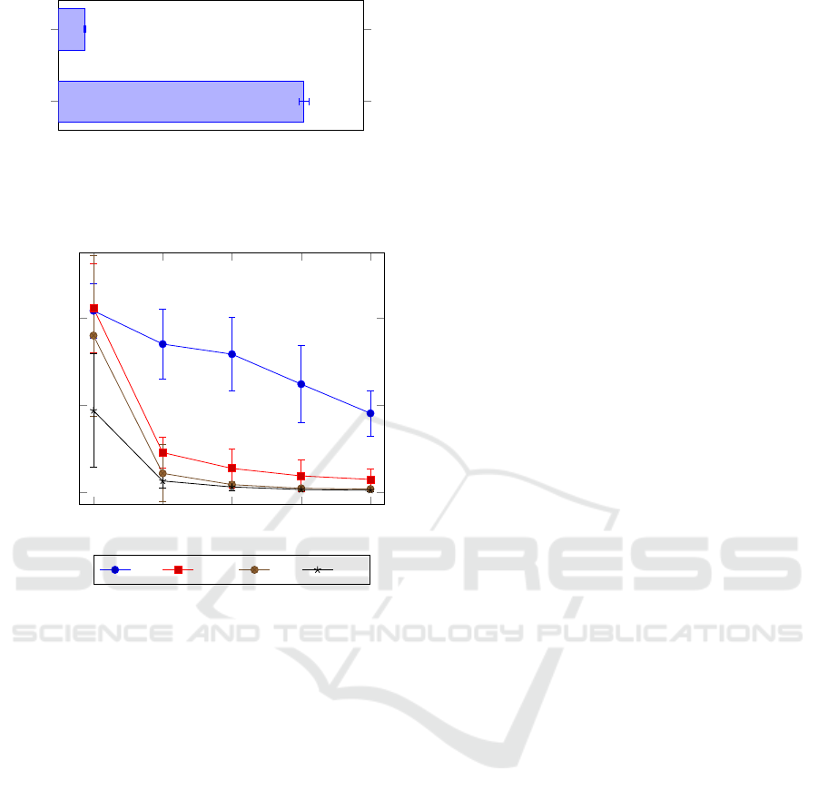
TCP
UDP
108.75
11.74
Throughput (Mbits/s)
Figure 6: FUSE network throughput for UDP and TCP net-
work traffic.
0
25 50 75
100
0
200
400
Delay (ms)
Video throughput (fps)
0% 0.2% 1% 2%
Figure 7: 720p video streaming performance between
FUSE nodes for increasing delay at several levels of packet
loss.
The rest of the chart follows the general shape pre-
dicted by the model. A roughly hyperbolic shape,
with an increase in packet loss causing a faster degra-
dation than an increase in delay. The general result
is that performance quickly drops to a useless level,
unless special care is taken to avoid noticeable packet
loss. While 0.2% loss combined with 100ms delay
still results in a useful stream at 29fps, as little as 1%
loss combined with 50ms delay results in only 17fps.
The only other good results were all obtained at 0ms
delay (0.25ms counting d
0
), but those are unrealis-
tic in practical federations, even if the nodes are very
close to each other geographically.
6 DISCUSSION AND FUTURE
WORK
A containerized approach makes FUSE easy to de-
ploy on any device that supports Docker. Addition-
ally, leveraging Kubernetes makes sure that container-
ized software can be deployed using familiar and reli-
able methods. However, FUSE can only be deployed
on devices that support Docker, and existing software
has to be containerized in order to be deployed in a
FUSE federation.
The introduction puts forth three challenges in
creating a federation service environment for crisis
situations:
1. Enabling and securing fast cross-domain commu-
nication while restricting access to non-federated
resources
2. Isolating the federation service environment from
other software
3. Ensuring fast and easy deployment of the federa-
tion service environment on a large range of de-
vices
It is shown that the FUSE architecture solves these
challenges by using OpenVPN to enable and secure
cross-domain traffic, and by using DinD to isolate
FUSE from other software running on a device and
simplifying deployment.
Tests are performed to empirically confirm the
parts of the challenges related to FUSE performance
and resource consumption.
The memory consumption and required disk space
tests confirm that FUSE can be deployed on a wide
range of devices, according to the third challenge.
However, master nodes have to process a lot of Open-
VPN traffic, which is CPU intensive, so devices with
at least 2 available cores and hardware encryption
such as AES-NI (Intel, 2018) are recommended.
Starting a FUSE federation is shown to be fast,
taking only 5 to 6 minutes. The time to join a fed-
eration is dependent on network quality, but barring
extremely hostile network conditions, a worker node
should take about 1 to 4 minutes to join a federation.
These numbers show that in most circumstances, it is
possible to set up an entire federation in 10 minutes or
less, which is enough to complete the third challenge.
Because the resource requirements for master nodes
are relatively low and every minute counts in crisis
situations, it could be a good idea to keep a master
node running at all times. This approach would cut
response time to just 1 to 4 minutes when a situation
arises.
The network performance of a FUSE federation
is explored by both measuring pure throughput and
by using a video streaming setup which mimics a
client PC viewing a security camera stream. The re-
sults of the throughput test suggest that most of the
performance limitations are due to OpenVPN. For
TCP traffic the network speed is acceptable and sat-
urates a 100 Mbit/s network. UDP is almost 10 times
slower, so applications running on a FUSE federa-
FUSE: A Microservice Approach to Cross-domain Federation using Docker Containers
97

tion should consider using TCP. Importantly, since
OpenVPN performance is CPU bound, not connec-
tion bound, this bandwidth has to be shared by all
worker nodes connected to the same master, which
needs to be taken into account when setting up a fed-
eration.
The video streaming test shows the performance
of streaming services under a variety of network con-
ditions. If 24 FPS is taken as a minimum requirement
for a smooth 720p video stream, performance is good
enough to handle 17 video streams simultaneously
under ideal circumstances, which is sufficient for the
first challenge. However, performance drops quickly
with increasing packet loss. Around 1% packet loss
and 50ms delay, UDP is likely a better choice, since
packet loss will only result in image corruption, but
no frame rate decrease. A simple mathematical model
has been worked out to predict FUSE TCP perfor-
mance, which could help evaluate the choice for ei-
ther TCP or UDP under a given set of circumstances.
In future work, OpenVPN performance could
likely be improved (OpenVPN, 2018), especially
since the test results show that FUSE throughput only
reaches about 10% of the capacity of the gigabit line
used for the tests. While improving OpenVPN per-
formance may not help for scenarios with low net-
work quality, it would at least increase throughput un-
der optimal network conditions, reduce CPU load, or
make larger worker pools practical. Alternatives to
OpenVPN, such as Wireguard
18
, are also considered.
A high availability mechanism should also be im-
plemented in the future. In the test setup, only one
master node is used, but a failure of the master node
would disrupt the entire federation. Some of the chal-
lenges are minimizing the number of hops for pod
traffic between master nodes, handling the indepen-
dent VPN networks started by each master, keeping
configuration information up to date over the entire
high availability network and making sure nodes get
delegated to a new master when one of them fails.
The creation of multiple master nodes can also re-
duce OpenVPN CPU load compared to a single mas-
ter, and optimize traffic flow. In a single master setup,
there is not only a centralized controller for the feder-
ation, but since all traffic between worker nodes has to
go via the master node’s VPN server, it flows accord-
ing to a star topology. In a high availability setup,
each master node would have its own star topology
formed by its set of worker nodes. Only when worker
nodes with different masters need to communicate
does any traffic flow between the master nodes, and
this sort of traffic could be minimized by planning or
reassigning worker nodes to a different master.
18
https://www.wireguard.com/
Kubernetes pods can be moved from one node
to another to ensure the load is distributed across
all nodes in the cluster. For stateless microservices
this poses no problem but services such as databases
or queues require backing storage that needs to per-
sist across the same instances regardless where they
run. This storage is typically configured in advance
and a Kubernetes volume plugin is deployed to al-
low for dynamic volume provisioning. In the context
of FUSE, further research can be done to automate
this deployment and dynamically increase the storage
through simple node labeling.
7 CONCLUSION
FUSE is introduced as a federation service environ-
ment to create and manage federations across do-
mains. Its architecture is shown to fulfill the require-
ments stated in the introduction. Tests show that
FUSE is fast and easy to deploy and that its hard-
ware requirements allow for deployment on low-end
hardware. Furthermore, FUSE is shown to be fast
enough for high quality video streaming, an impor-
tant practical use case. Note that the test is primarily
aimed at measuring FUSE network performance and
stability, while camera streams in real crisis situations
may have more varying results. Potential future work
is discussed to improve the speed and reliability of
FUSE, which includes optimizing or replacing Open-
VPN, adding support for a high availability setup and
managing storage.
ACKNOWLEDGMENT
FUSE is a project realized in collaboration with imec.
Project partners are Barco, Axians and e-BO Enter-
prises, with project support from VLAIO (Flanders
Innovation & Entrepreneurship).
REFERENCES
Amaral, M., Polo, J., Carrera, D., Mohomed, I., Unuvar,
M., and Steinder, M. (2015). Performance evalua-
tion of microservices architectures using containers.
In 2015 IEEE 14th International Symposium on Net-
work Computing and Applications, pages 27–34.
Atrey, A., Moens, H., Seghbroeck, G. V., Volckaert, B., and
Turck, F. D. (2016). Design and evaluation of au-
tomatic workflow scaling algorithms for multi-tenant
SaaS. In Proceedings of the 6th International Con-
ference on Cloud Computing and Services Science.
CLOSER 2019 - 9th International Conference on Cloud Computing and Services Science
98

SCITEPRESS - Science and and Technology Publi-
cations.
Bernstein, D. (2014). Containers and cloud: From LXC
to docker to kubernetes. IEEE Cloud Computing,
1(3):81–84.
Bottoni, P., Gabrielli, E., Gualandi, G., Mancini, L. V.,
and Stolfi, F. (2016). FedUp! cloud federation as a
service. In Service-Oriented and Cloud Computing,
pages 168–182. Springer International Publishing.
Bui, T. (2015). Analysis of docker security.
Burns, B. (2018). Designing distributed systems (the side-
car pattern).
Cailliau, E., Aerts, N., Noterman, L., and De Groote, L.
(2016). A comparative study on containers and related
technologies.
Casalicchio, E. (2017). Autonomic orchestration of con-
tainers: Problem definition and research challenges.
In Proceedings of the 10th EAI International Confer-
ence on Performance Evaluation Methodologies and
Tools. ACM.
Felter, W., Ferreira, A., Rajamony, R., and Rubio, J. (2015).
An updated performance comparison of virtual ma-
chines and linux containers. In 2015 IEEE Interna-
tional Symposium on Performance Analysis of Sys-
tems and Software (ISPASS). IEEE.
Intel (2018). Intel data protection technology with aes-ni
and secure key.
Jennings, B. and Stadler, R. (2015). Resource management
in clouds: Survey and research challenges. Journal of
Network and Systems Management, 23(3):567–619.
Kratzke, N. (2017). About microservices, containers and
their underestimated impact on network performance.
Kubernetes (2016). Security best practices for kubernetes
deployment.
Kubernetes (2018). Kubernetes federation.
Miraftabzadeh, S. A., Rad, P., and Jamshidi, M. (2017).
Distributed algorithm with inherent intelligence for
multi-cloud resource provisioning. In Intelligent De-
cision Support Systems for Sustainable Computing,
pages 77–99. Springer International Publishing.
Morabito, R., Cozzolino, V., Ding, A. Y., Beijar, N., and
Ott, J. (2018). Consolidate IoT edge computing with
lightweight virtualization. IEEE Network, 32(1):102–
111.
Moreno-Vozmediano, R., Huedo, E., Llorente, I. M., Mon-
tero, R. S., Massonet, P., Villari, M., Merlino, G., Ce-
lesti, A., Levin, A., Schour, L., V
´
azquez, C., Melis, J.,
Spahr, S., and Whigham, D. (2016). Beacon: A cloud
network federation framework. In Celesti, A. and Leit-
ner, P., editors, Advances in Service-Oriented and
Cloud Computing, pages 325–337, Cham. Springer
International Publishing.
OpenVPN (2018). Openvpn optimizing performance on gi-
gabit networks.
Recordon, D. and Reed, D. (2006). Openid 2.0: A platform
for user-centric identity management. In Proceed-
ings of the Second ACM Workshop on Digital Identity
Management, DIM ’06, pages 11–16, New York, NY,
USA. ACM.
Samie, F., Tsoutsouras, V., Bauer, L., Xydis, S., Soudris, D.,
and Henkel, J. (2016). Computation offloading and
resource allocation for low-power IoT edge devices.
In 2016 IEEE 3rd World Forum on Internet of Things
(WF-IoT). IEEE.
Shi, W. and Dustdar, S. (2016). The promise of edge com-
puting. Computer, 49(5):78–81.
Verma, A., Pedrosa, L., Korupolu, M., Oppenheimer, D.,
Tune, E., and Wilkes, J. (2015). Large-scale cluster
management at google with borg. Proceedings of the
10th European Conference on Computer Systems, Eu-
roSys 2015.
Vermeulen, B., Van de Meerssche, W., and Walcarius, T.
(2014). jfed toolkit, fed4fire. In Federation. In: GENI
Engineering Conference, volume 19.
Wang, Z. and Su, X. (2015). Dynamically hierarchical
resource-allocation algorithm in cloud computing en-
vironment. J. Supercomput., 71(7):2748–2766.
Wauters, T., Vermeulen, B., Vandenberghe, W., Demeester,
P., Taylor, S., Baron, L., Smirnov, M., Al-Hazmi, Y.,
Willner, A., Sawyer, M., Margery, D., Rakotoarivelo,
T., Lobillo Vilela, F., Stavropoulos, D., Papagianni,
C., Francois, F., Bermudo, C., Gavras, A., Davies, D.,
Lanza, J., and Park, S.-Y. (2014). Federation of inter-
net experimentation facilities: architecture and imple-
mentation. In European Conference on Networks and
Communications, Proceedings, pages 1–5.
Whaiduzzaman, M., Haque, M., Karim Chowdhury, R., and
Gani, A. (2014). A study on strategic provisioning of
cloud computing services. The Scientific World Jour-
nal, 2014.
FUSE: A Microservice Approach to Cross-domain Federation using Docker Containers
99
