
IoT based Driver Information System for Monitoring the
Load Securing
Jurij Kuzmic
1
, Günter Rudolph
1
, Walter Roth
2
and Michael Rübsam
2
1
Department of Computer Science, TU Dortmund University, Otto-Hahn-Str. 14, Dortmund, Germany
2
Dept. of Computer Science, South Westphalia University of Applied Sciences, Frauenstuhlweg 31, Iserlohn, Germany
Keywords: Load Securing System, Load Cell Sensor, VL6180X Proximity and Ambient Light Sensing Module,
CNY70 Reflective Optical Sensor, Miniature Snap-Action Switch, Wireless Technology, Encryption of
Transmitted Data, Development and Analysis of 433 MHz Radio Link, Power Supply of the Electronic
Cargo Strap Systems, Back End, Front End, Practical Real World Tests.
Abstract: This paper presents an electronic cargo strap system for monitoring load securing in trucks and car trailers.
Various measuring techniques and sensors for measuring the force on lashing belts are investigated. In
addition, a data access layer (back end) and a presentation layer (front end) have been developed for the
system in order to be able to monitor the load while driving. Moreover, radio data transmission, encryption
of transmission data and power supply of the systems has been realized. Furthermore, some prototypes have
been created in order to test the developed systems. A series of practical tests have been performed to test
the electronic cargo strap systems under real-world conditions.
1 INTRODUCTION
Many accidents and road closures occur due to non-
monitored load securing during transportation of
loaded goods in heavy goods vehicles, also causing
transport damages of the loaded goods, which
further increases the costs. To counteract this
problem, this paper introduces a system for
monitoring the load securing in trucks and car
trailers.
Various measuring methods and sensors have
been investigated. The sensors for measuring the
force on the lashing belt have been analysed and
tested. To prove the long-term stability, all sensors
were operated in continuous long-term tests. The
cost of the individual sensor must be very low for
this application because there are many lashing
straps used on a typical truck. Monitoring and
display of measured data has been implemented as a
mobile application running on an Android tablet.
Furthermore, power consumption of our
electronic cargo strap systems including sensor and
microcontroller has been investigated. Additionally,
a power supply suitable for real world use featuring
easy replacement of batteries has been developed.
Long service life of these systems without replacing
the batteries is highly desirable.
The radio data transmission between the data
access layer (back end) and the electronic cargo
strap systems has been examined. Here it is
important that the radio link requires very little
energy in order to be able to run the electronic cargo
strap systems with the same energy supply for years.
A simple encryption of the data has been
implemented to address the need not to transmit
clear text data via the radio link.
Most of the work in this project was done at the
South Westphalia University of Applied Sciences in
Iserlohn (Kuzmic A1, 2018). Furthermore, several
prototypes of the electronic cargo strap systems were
produced in order to test them in real-world
deployments.
To the best of our knowledge, there is no other
research in this area. For this reason, the references
are tutorials and sensor datasheets, and therefore not
related scientific work. According to our research,
no product exists on the market for monitoring the
load securing so far. There is only one patent
(Bruhn, 2014) for a similar system which describes
other sensors.
262
Kuzmic, J., Rudolph, G., Roth, W. and Rübsam, M.
IoT based Driver Information System for Monitoring the Load Securing.
DOI: 10.5220/0007710302620269
In Proceedings of the 4th International Conference on Internet of Things, Big Data and Security (IoTBDS 2019), pages 262-269
ISBN: 978-989-758-369-8
Copyright
c
2019 by SCITEPRESS – Science and Technology Publications, Lda. All rights reserved
2 SYSTEM ARCHITECTURE OF
LOAD SECURING SYSTEM
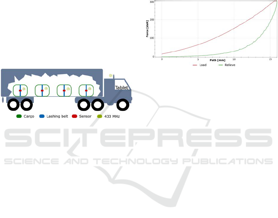
The system architecture describes the interactions
between developed components. Load is secured in
the vehicle using lashing belts and is monitored by
the electronic cargo strap systems. The data
measured by the sensors attached to the lashing belt
are transmitted from the truck semi-trailer to a truck
cabin via 433 MHz radio link. Data are displayed for
the truck driver on a tablet in the cab (Fig. 1). The
conversion from raw analog sensor value to force on
the lashing belt is performed by the microcontroller
of the sensor-transmitter unit. The mechanical
DoMess2 force meter (Dolezych, 2018) is used as a
starting point for the electronic cargo strap systems.
Figure 1: System architecture (interaction between truck
semi-trailer and truck cabin).
During development of the electronic cargo strap
systems, a hysteresis of measured values was
recognized. This is due to the physical assembly of
the DoMess2 force meter and the stretching of the
lashing belt and the built-in compression springs
(Rudolph, 2017). It can be seen in the diagram (Fig.
2) created by the pull-off force machine that the path
is not identical during increasing and relieving the
force on the lashing straps. When increasing the
force on the DoMess2 force meter, the force of 200
daN is reached at a position of about 12 millimetres.
However when relieving, the same force is reached
at 15 millimetres. The stretching of the lashing strap
and the mechanics are included in this diagram. daN
is the abbreviation for the unit of force Dekanewton
(10 Newtons). This corresponds approximately to
the weight of one kilogram (Wikipedia.org A1,
2018).
However hysteresis plays a minor role in the
development of the electronic cargo strap systems.
Because the relieving curve is relevant when
verifying force during transport, only the relieving
curve must be examined. Furthermore Figure 2
shows, that while relieving the DoMess2 force meter
the distance from 200 to 300 daN is only about 0.9
millimetres. This means that the sensor must be very
sensitive in order to be able to perceive minimal
changes of the distance. Optimizing the larger spring
forces may reduce the hysteresis, but this was not
tested. The steps in the relieving curve diagram
result from stopping at different levels of force on
the pull-off force machine. The force was held in
these conditions for ten seconds at each step.
Figure 2: Hysteresis of load and relieve the lashing strap.
3 ANALYSIS OF SENSORS
The following sections examine four possible
sensors for measuring the force on the lashing belts.
Arduino Pro Mini microcontrollers (Rohner, 2015)
are used to read the sensors.
3.1 Load Cell Sensor
The load cell sensor is the standard measuring
device installed in commercial digital personal
scales (Instructables.com A1, 2018). This sensor
contains two strain gauges, which change their
resistance during compression or stretching (Al-
Mutlaq, 2018).
This type of sensor needs a load cell
amplifier, because the changes of resistance are very
small. The breakout board HX711
(Forum.arduino.cc, 2018) can be used for this. It
contains all components required for amplification
of the resistance changes. To obtain correct readings
for two load cell sensors, two half Wheatstone
bridges (dual half bridge) have to be constructed
(Youtube.com, 2016). This type of circuit is
commonly used to measure small ohmic resistance
changes. After some short-term measurements, the
question arises as to whether the load cell sensors
are long-term stable. To answer this question, a
continuous operating test was run for about two
weeks. The starting weight in this test was 410
grams. As can be seen in next figure (Fig. 3), the
reading values vary significantly over time. The
deviation in this case is up to 76 percent. Although
these sensors are ideal for a short measurement in a
IoT based Driver Information System for Monitoring the Load Securing
263
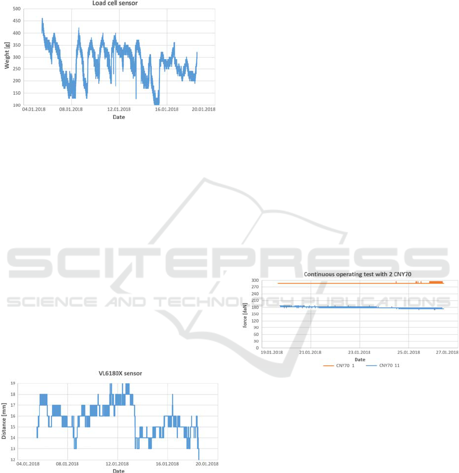
digital personal scale, they can not be used for
continuous operation. For this reason, load cell
sensors are inappropriate for measuring forces on
lashing belts.
Figure 3: Continuous operating test of load cell sensor.
3.2 VL6180X Proximity and Ambient
Light Sensing Module
The next type of sensor investigated was the
VL6180X Time-of-Flight proximity and ambient
light sensor. Because the VL6180X uses infrared
pulses for measurement, it is widely independent of
colour and surface properties of the target (Pololu,
2018).
After wiring and programming (Github.com,
2016) of the components, a distance measurement
test was performed with this sensor. From this test, it
was found out that the VL6180X sensor is suitable
for measuring distances in the mm range. It provides
a digital read out of the distance to the object in
millimetres. To determine whether this sensor can be
used permanently for the electronic cargo strap
system, a continuous operating test with three
sensors for about two weeks was carried out (Fig. 4).
Figure 4: Continuous operating test of one of three
VL6180X sensors.
The three continuous operating tests were
executed in parallel. All three VL6180X sensors
fluctuate between 4-7 millimetres. The minimum
resolution of the sensor is one millimetre, which is
within the requirements for measuring lashing belt
forces. Nevertheless, the discovered fluctuations
make these sensors too inaccurate with regard to
long-term stability. The VL6180X sensors are
therefore not suitable for measuring the force on
lashing belts because the maximum lift of the
mechanical DoMess2 force meter used is only ten
millimetres and the fluctuations of the sensors were
4 mm, equivalent to 40% of the measuring range.
However, the measuring range is in centimetres,
VL6180X sensors may be used.
3.3 CNY70 Reflective Optical Sensor
with Transistor Output
This chapter investigates the usability of the CNY70
reflective optical sensor with transistor output
(Mischnick and Mischnick, 2007) for the electronic
cargo strap system. In order to check whether the
sensor is suitable for measuring, it was installed in a
syringe in the first step. The syringe was taped with
black tape, so that the outside light did not affect the
light from the sensor’s LED. Because each of these
analog sensors shows different measured values with
the same applied voltage, they must be calibrated
before measuring. In principle, these sensors are
suitable for measuring distances. They passed the
continuous operating tests very well, showing
excellent long-term stability (Fig. 5).
Figure 5: Continuous operating test of two CNY70
sensors.
An average function is used to convert the raw
analog value of the sensor voltage to the force on the
lashing belt (Dekanewton). Because the curve
progression of the sensors is identical, the measured
ratio of the sensor can be represented on a
percentage basis on this average curve. For this only
the start and end values of the measurement range
determined during calibration of the sensor are
required. During test measurements and continuous
operating tests it turned out that although CNY70
sensors are suitable for measuring the distance in the
DoMess2 force meter, they are very sensitive to
external light and mechanical impact. Furthermore,
it has been noticed that material and colour of the
reflective surface play a major role in the
IoTBDS 2019 - 4th International Conference on Internet of Things, Big Data and Security
264
measurement. However, because of the good results
of test measurements and continuous operation tests,
several prototypes were produced for field tests in
the real world.
3.4 Miniature Snap-action Switch
Another possibility for monitoring load securing is
the miniature snap-action switch known from
electrical engineering. These switches are nowadays
a standard component in many electrical appliances.
A great advantage of micro switches is their working
temperature range between - 25°C and + 85°C. In
addition, they support up to a million operations
(Produktinfo.conrad.com, 2018). Micro switches can
be used in different ways. Using all three existing
connections, the electrical switch can be wired as a
changeover contact. If only two connections of the
micro switch are used, it acts as a NO (normally
open) or NC (normally closed) (Wikipedia.org A2,
2018) device. In the electronic cargo strap system,
the micro switch is used as a normally open switch.
Because the micro switches behave like security
contacts, and load security requires a certain
minimum force on the lashing belts, they are well
suited for monitoring load securing when their
trigger point is set to this minimum force. This point
can be adjusted on a pull-off force machine. For this
reason, two such prototypes are created.
4 WIRELESS TECHNOLOGY
The 433 MHz wireless technology was chosen as
radio technology for the system. WLAN (wireless
local area network) wireless technology was used
successfully in a previously created prototype
(Kuzmic A2, 2017) with ESP8266 microcontrollers
(not discussed in this paper). Based on this, it was
known that a WLAN connection is indeed stable and
secure due to WPA2 encryption, but it requires a lot
of energy. Therefore, WLAN wireless technology
with the ESP8266 can not be used when operating
with batteries as in this paper. Another alternative
investigated was Bluetooth wireless technology.
Previous projects revealed that this technology has
range problems using less transmission power
(powering with batteries), but this was not explicitly
tested in this project. Therefore, it can not be used in
the development of the electronic cargo strap
system. In the two previously presented wireless
technologies, a permanent connection between
transmitter and receiver is established. Thus, the
transmission process lasts longer and uses a lot of
energy. In 433 MHz wireless technology, however,
no connection between the transmitter and the
receiver is established. Messages are sent without
knowing whether they have actually arrived at the
receiver, like User Datagram Protocol (UDP).
Therefore, 433 MHz radio technology requires much
less energy and can achieve long range in optimal
conditions. For this reason, this wireless technology
was used in our system.
4.1 Encryption of Transmitted Data
To ensure that messages are not transmitted in plain
text over the 433 MHz radio link, the transmission
data is encrypted with an enhanced Caesar
encryption. This should show in principle the
possibility of cryptography. Of course, in the next
step the primitive Caesar algorithm needs to be
replaced with a state of the art encryption like the
Rabbit stream cipher, which requires only a rather
small extra amount of code.
4.2 Analysis of 433 MHz Radio Link
To understand what really happens on the 433 MHz
radio link between transmitter and receiver, the 433
MHz radio link was analysed (Instructables.com A2,
2018; Rtl-sdr.com, 2013) using software-defined
radio (SDR) technology. This analysis uses digital
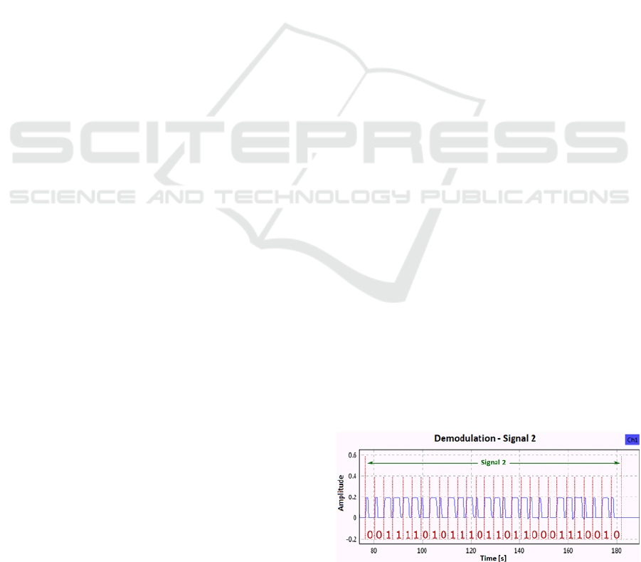
signal processing. Coding of the bits in a 433 MHz
connection is as follows: 0 = 100 and 1 = 110
(Pérez, 2013). The 433 MHz transmitter and the 433
MHz receiver modules (FS1000A and XD-RF-5V)
for Arduino use amplitude-shift on-off keying
(ASK-OOK) (Mietke, 2018). This is a form of
amplitude modulation (AM) (Wikipedia.org A3,
2018). To check what the binary code on the radio
link looks like, a test message is sent. The bit
sequence of this message looks like this:
"1111010111011011000111001".
After demodulating the signal, the same bit
pattern can be successfully detected from the air.
The next figure (Fig. 6) shows this demodulation
(Rascagnères, 2015).
Figure 6: Diagram of bit sequence from signal two.
IoT based Driver Information System for Monitoring the Load Securing
265
During testing the transmission range of the
systems, the messages of all ten test systems could
be received at a distance of ten metres from the
transmitter to the receiver. This test was carried out
without any obstacles between transmitter and
receiver. To increase the transmission distance,
professional antennas could be installed. If this does
not solve this problem, 433 MHz repeaters can be
installed on the truck semi-trailer.
5 POWER SUPPLY
According to a market analysis, the Arduino Pro
Mini microcontrollers are known to consume very
little power and are often used as microcontrollers
for powering with batteries (Wikipedia.org A4,
2018). Due to the fact that these microcontrollers
consume very little energy in sleep mode (Deep
Sleep) compared to other microcontrollers, they can
be operated for years without changing batteries
(Home-automation-community, 2018). For this
reason, these microcontrollers were chosen for the
electronic cargo strap system. Of course, the final
power consumption is also affected by the connected
sensors and actuators. Furthermore, Arduino Pro
Mini microcontrollers do not require an external
low-dropout (LDO) regulator. This is already
installed on the standard demo board
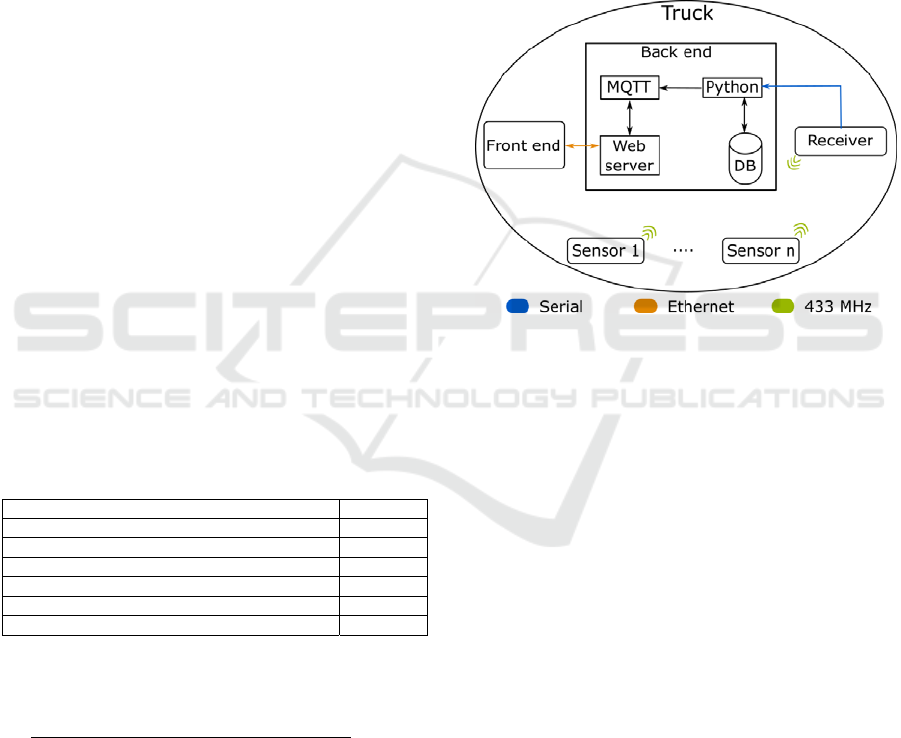
(Cdn.sparkfun.com, 2018). The following table
(Tab. 1) illustrates the key data for an example
calculation of continuous operation.
Table 1: Key data for battery life.
Battery
t
ype NiMH
Capacity of a battery (mAh) 2500
Power consumption in sleep mode (mA) 0,03293
Power consumption in normal mode (mA) 21,08
Interval duration (s) 600
Duration in sleep mode (s) 598
Duration in normal mode (s) 2
The following shows an example of the
theoretical calculation of the battery life:
2500 ∗ 600
21.08 ∗ 2 0.03293 ∗ 598
24261.4
33.2
(1)
Every ten-minute interval (600 seconds), the
microcontroller switches from sleep mode to normal
mode. In normal mode two seconds are needed for
reading the sensor and transmitting the sensor’s
value via the 433 MHz interface. During the
remaining 598 seconds of a 600 second interval the
microcontroller is in sleep mode (Deep Sleep). This
calculation (Eq. 1) refers to the CNY70 sensors
currently installed in the electronic cargo strap
system. This also shows that theoretical battery life
is approx. 3 years in continuous operation.
6 SOFTWARE ARCHITECTURE
Software architecture (Fig. 7) describes the
interaction of the sensors with the presentation layer
(front end) and the data access layer (back end).
Figure 7: Software architecture of the monitoring system.
The electronic cargo strap systems transmits the
measured data over a 433 MHz radio link. Data are
received by a 433 MHz receiver connected to the
data access layer (back end). Next, the received data
are streamed to a Python script in the back end.
Received data are evaluated in this Python script and
stored in the database. Furthermore, the analysed
data and alarm messages are passed from the Python
script to the MQTT broker and thus to the
presentation layer (front end). In the next step,
incoming data are displayed in an Android
application via the web server.
Communication between back end and front end
is realized via a REST interface, working via
Ethernet over USB (Universal Serial Bus), because a
cable connection is more stable and less susceptible
to interference. Of course, this connection can also
be a wireless connection.
6.1 433 MHz Receiver
The microcontroller for the 433 MHz receiver (XD-
RF-5V) uses the demo board NodeMCU ESP8266.
This board contains all components necessary for
Plug and Play (PnP). The internal serial adapter
IoTBDS 2019 - 4th International Conference on Internet of Things, Big Data and Security
266
provides access to the back end via USB.
6.2 Back End
The back end of the software includes the
components Apache HTTP server, MariaDB
relational database, Mosquitto MQTT broker and a
Python script. These run on a Raspberry Pi 3 with a
solid-state drive (SSD) (Raspberry.tips, 2017). After
the back end system is started, the Python script is
executed as a service (Wiki.ubuntuusers.de, 2018).
This service connects to the MQTT broker and in the
next step checks using an endless loop whether data
have arrived from the 433 MHz receiver via the
serial interface.
Once data are available, they will be reviewed
first. After review and evaluation of the message,
metrics and alerts are forwarded to the front end. If
errors occur in the function, in the receiver or in the
transmitter, these are sent to the surface additionally.
Moreover, each measured value, alarm message and
error message is stored permanently in the database
for possible further evaluations.
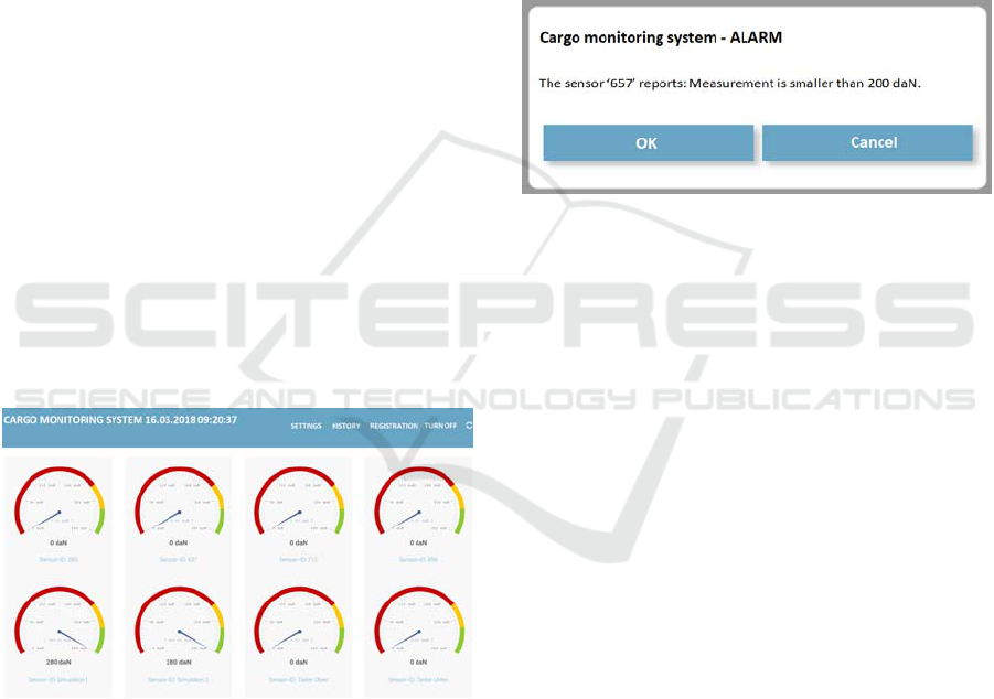
6.3 Front End
The user interface of the front end consists of an
Android application that displays the data in a
WebView (Fig. 8). The data for the display are
provided by the HTTP web server.
Figure 8: User interface of the monitoring system with
eight monitored sensors (translation from German).
As soon as measured values of the electronic
cargo system arrive on the monitoring page, a new
JavaScript gauge for this system is created and
displayed. If the JavaScript gauge exists already for
a particular sensor, the measured values of this
sensor are updated and displayed as daN. If an error
message is forwarded from the back end to the front
end, it will appear on the monitoring page
immediately. As soon as measured values of a
lashing belt fall below the minimum allowable force
predefined in the settings, an alarm message appears
on the monitoring page (Fig. 9) including the
system’s sensor identification number. If a name
was manually set when registering the electronic
cargo strap system, this name will be displayed on
the monitoring page instead of the sensor
identification number.
In addition to the visual notification, the user is
warned by an audible warning signal from the
Android device. If this alarm is ignored or not
confirmed, the notification will be displayed again
when the next measured value of the system is
received.
Figure 9: Alarm message on the monitoring page
(translation from German).
7 PRACTICAL TESTS
For practical tests of the developed systems, four
real-world deployments were carried out.
7.1 Lashing Belt Elongation Test
For this test a metal box weighing about 600
kilograms and filled with scrap metal, was fastened
on a car trailer using the developed electronic cargo
strap system. Because the metal box can not be
compressed by the lashing strap, it was possible to
measure the elongation of the lashing strap
successfully while driving. After about 1.3
kilometres, the lashing strap had completely
extended and had to be retightened. It had also been
proven that driving in curves and acceleration has an
effect on the measured force on the lashing belt.
7.2 Crucial Test
To detect whether the developed electronic cargo
strap system notifies users even when the lashing
belt tear (Lasiportal.de, 2018), a successful
emergency test was performed (Fig. 10).
IoT based Driver Information System for Monitoring the Load Securing
267
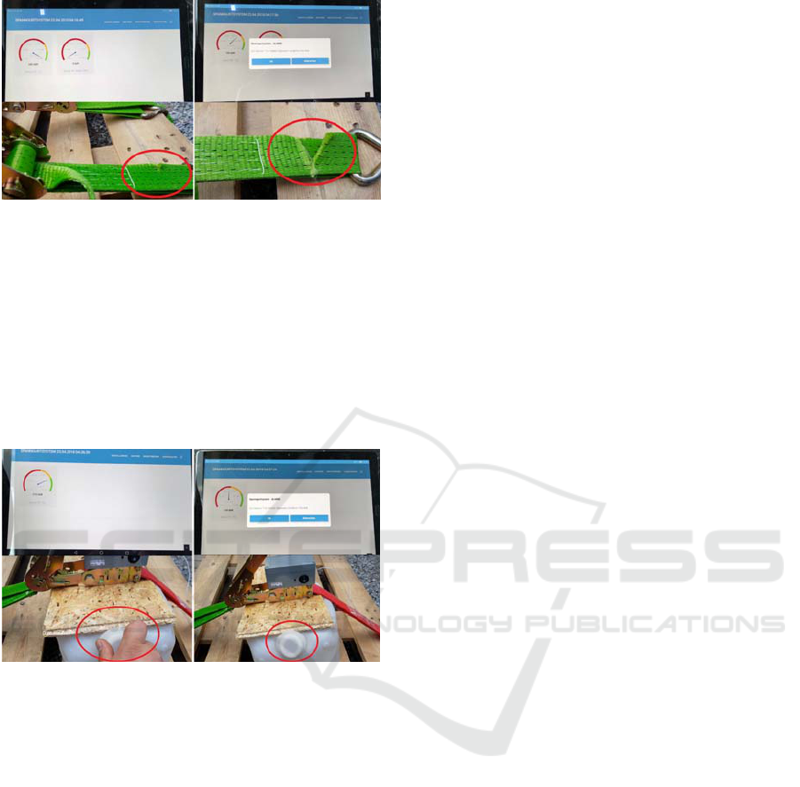
Figure 10: Alarm message during the crucial test. Left:
Intact lashing belt. Right: Torn lashing belt.
7.3 Pressure Test
Another possible scenario (Fig. 11) for load securing
is the transport and attachment of pallets with soft
material. Because in these cases the load seems to be
secured at first glance, but over the time of driving,
the soft material may compress and the cargo will no
longer be secured.
Figure 11: Alarm message during the pressure test. Left:
Closed cap of the canister. Right: Opened cap of the
canister.
7.4 Transmission Test
A final and important practical test for the electronic
cargo strap systems was the transmission test. In this
test, it was observed that vehicle speed have a
negative effect on the transmission of the sensor
data. The use of more professional antennas would
significantly improve the result in our opinion.
8 CONCLUSIONS
Overall, the driver information system for
monitoring the load securing worked well. The
CNY70 reflective optical sensors were used
successfully. However, it was noticed that they are
very sensitive to the colour and the material of a
reflective surface. It was also noticed that ambient
light and slight impact affect the measurement.
In order to achieve a greater range for the
transmission of the measured data, more
professional antennas are recommended. These
should point to different directions. The antennas
could look like a wireless router, which usually
contain three antennas for sending and receiving
from different directions. An alternative would be to
install 433 MHz repeaters on the truck semi-trailer.
Another option for wireless data transmission could
be Zigbee (Wikipedia.org A5, 2018). This data
transfer technology can achieve long ranges and is
often used on various Internet of Things (IoT)
devices. For improved receipt in the cab of the truck,
the receiver antenna should be mounted outside the
cab. It should be noted that the maximum cable
length of USB connection is not exceeded. If
necessary, it makes more sense to extend the 1-Wire
connection (Maxim Integrated Products, 2008) to the
Arduino receiver module rather than the USB
connection (Wikipedia.org A6, 2018) from the
receiver to the back end system.
A second option for the sensor for the electronic
cargo system is a miniature snap-action switch. The
fact that this micro switch can be installed in a
simple mechanical device can quickly turn this
prototype into a product. In addition, the micro
switches do not respond to ambient light,
temperature and slight impact like other analysed
sensors. However, it is still a long way to a
successful product.
REFERENCES
Al-Mutlaq, S., 2018. Getting Started with Load Cells,
Sparkfun.com. [online]. Available at:
https://learn.sparkfun.com/tutorials/getting-started-
with-load-cells.
Bruhn, D., 2014. Electronic monitoring of load securing of
vehicles, Patents.google.com. [online]. Available at:
https://patents.google.com/patent/DE102014012508A
1/en?oq=DE102014012508A.
Cdn.sparkfun.com, 2018. Arduino Pro Mini 8MHz/3.3V,
Sparkfun.com. [online]. Available at:
https://cdn.sparkfun.com/datasheets/Dev/Arduino/Boa
rds/ProMini8MHzv1.pdf.
Dolezych, 2018. DoMess 2 Vorspannkraftmessgerät,
Dolezych.de. [online]. Available at:
https://dolezych.de/domess-2-vorspannkraftmessgerat-
dolezych.
Forum.arduino.cc, 2018. HX711 – Bild, Arduino.cc.
[online]. Available at: https://forum.arduino.cc/
index.php?action=dlattach;topic=486101.0;attach=216
741
IoTBDS 2019 - 4th International Conference on Internet of Things, Big Data and Security
268

Github.com, 2016. VL6180X library for Arduino,
Github.com. [online]. Available at:
https://github.com/pololu/vl6180x-arduino.
Home-automation-community, 2018. Arduino Low Power
- How To Run ATmega328P For a Year On Coin Cell
Battery, Home-Automation-community.com. [online].
Available at: http://www.home-automation-
community.com/arduino-low-power-how-to-run-
atmega328p-for-a-year-on-coin-cell-battery/.
Instructables.com A1, 2018. Arduino Bathroom Scale
With 50 Kg Load Cells and HX711 Amplifier,
Instructables.com. [online]. Available at:
http://www.instructables.com/id/Arduino-Bathroom-
Scale-With-50-Kg-Load-Cells-and-H/.
Instructables.com A2, 2018. RTL-SDR FM Radio Receiver
With GNU Radio Companion, Instructables.com.
[online]. Available at: http://www.instructables.com/
id/RTL-SDR-FM-radio-receiver-with-GNU-Radio-
Companion/.
Kuzmic A1, J., 2018. Driver information system for
monitoring the load securing (German:
Fahrerinformationssystem zur Überwachung der
Ladungssicherung), Master’s thesis, South Westphalia
University of Applied Sciences.
Kuzmic A2, J., 2017. Prototyping of a microcontroller-
based wireless sensor system for central monitoring
the force in lashing straps (German: Entwicklung des
Prototypen eines Mikrocontroller basierenden Funk-
Sensorsystems zur zentralen Überwachung der
Vorspannkraft von Zurrgurten), Master’s project,
South Westphalia University of Applied Sciences.
Lasiportal.de, 2018. Ladung durch einen (zerrissenen)
Zurrgurt gesichert, Lasiportal.de. [online]. Available
at: https://www.lasiportal.de/seminare-und-
schulungen/bilder/mangelhafte-
ladungssicherung/brisante-ladung-durch-einen-
zerrissenen-zurrgurt-gesichert/
Maxim Integrated Products, 2008. Guidelines for Reliable
Long Line 1-Wire Networks, Maximintegrated.com.
[online]. Available at:
https://www.maximintegrated.com/en/app-
notes/index.mvp/id/148
Mietke, D., 2018. Amplitudenumtastung – ASK,
Elektroniktutor.de. [online]. Available at:
https://elektroniktutor.de/signalkunde/ask.html
Mischnick, S., Mischnick, J., 2007. 1.2.12 Der
Reflexkoppler CNY 70, Strippenstrolch.de. [online].
Available at: http://www.strippenstrolch.de/1-2-12-
der-reflexkoppler-cny70.html
Pérez, X., 2013. Decoding 433MHz RF data from wireless
switches. The data, Tinkerman.cat. [online]. Available
at: https://tinkerman.cat/decoding-433mhz-rf-data-
from-wireless-switches-the-data/
Pololu, 2018. VL6180X Time-of-Flight Distance Sensor
Carrier with Voltage Regulator, 60cm max,
Pololu.com. [online]. Available at:
https://www.pololu.com/product/2489
Produktinfo.conrad.com, 2018. DG sub-subminiature
switch, Conrad.com. [online]. Available at:
http://www.produktinfo.conrad.com/datenblaetter/700
000-724999/705504-da-01-en-SUBSUBMINIATUR_
DG23_B1LA_0_05A_30V.pdf.
Rascagnères, P., 2015. 433MHz ASK signal analysis,
Bytebucket.org. [online]. Available at:
https://bytebucket.org/rootbsd/433mhz-ask-signal-
analysis/raw/5f4937e4efb2198abcc375b8aefee414219
41fca/pdf/433MHz_ASK_sginal_analysis-Wireless_
door_bell_adventure-1.0.pdf.
Raspberry.tips, 2017. Raspberry Pi von SSD Festplatte
booten, Raspberry.tips. [online]. Available at:
https://raspberry.tips/raspberrypi-tutorials/raspberry-
pi-von-ssd-festplatte-booten/.
Rohner, A., 2015. How to make the Watchdog timer work
on an Arduino Pro Mini by replacing the bootloader,
Andreasrohner.at. [online]. Available at:
https://andreasrohner.at/posts/Electronics/How-to-
make-the-Watchdog-Timer-work-on-an-Arduino-Pro-
Mini-by-replacing-the-bootloader/
Rtl-sdr.com, 2013. Tutorial: Creating an FM Receiver in
GNURADIO using an RTL-SDR source, Rtl-sdr.com.
[online]. Available at: https://www.rtl-
sdr.com/tutorial-creating-fm-receiver-gnuradio-rtl-sdr/
Rudolph, D., 2017. Resultierende Kraft / Kräfte zerlegen,
[online]. Available at: https://www.frustfrei-
lernen.de/mechanik/kraefte-zerlegen-resultierende-
kraft.html.
Wikipedia.org A1, 2018. Newton (Einheit), Wikipedia.org.
[online]. Available at: https://de.wikipedia.org/
wiki/Newton_(Einheit)
Wikipedia.org A2, 2018. Mikroschalter, Wikipedia.org
URL: https://de.wikipedia.org/wiki/Mikroschalter
Wikipedia.org A3, 2018. Amplitudenumtastung,
Wikipedia.org. [online]. Available at:
https://de.wikipedia.org/wiki/Amplitudenumtastung
Wikipedia.org A4, 2018. Mignon (Batterie),
Wikipedia.org. [online]. Available at:
https://de.wikipedia.org/wiki/Mignon_(Batterie)
Wikipedia.org A5, 2018. Zigbee, Wikipedia.org. [online].
Available at: https://en.wikipedia.org/wiki/Zigbee
Wikipedia.org A6, 2018. Universal Serial Bus,
Wikipedia.org. [online]. Available at:
https://de.wikipedia.org/wiki/Universal_Serial_Bus
Wiki.ubuntuusers.de, 2018. Service Units,
Ubuntuusers.de. [online]. Available at:
https://wiki.ubuntuusers.de/systemd/Service_Units/
Youtube.com, 2016. Load Cell, Youtube.com. [online].
Available at: https://www.youtube.com/watch?v=
0Lwdzpr_TxM
IoT based Driver Information System for Monitoring the Load Securing
269
