
SeeDep: Deploying Reproducible Application Topologies on Cloud
Platform
Cyril Seguin
1,2
, Eddy Caron
2
and Samuel Dubus
3
1
Inria, France
2
ENS Lyon, LIP, France
3
Nokia bell labs, France
Keywords:
Reproducibility, Network Topology, Application Topology, Cloud Deployment.
Abstract:
As part of the scientific method, any researcher should be able to reproduce the experimentation in order to
not only verify the result but also evaluate and compare this experimentation with other approaches. The need
of a standard tool allowing researchers to easily generate, share and reproduce experiments set-up arises. In
this paper, we present SeeDep, a framework aiming at being such a standard tool. By associating a generation
key to a network experiment set-up, SeeDep allows for reproducing network experiments independently from
the used infrastructure.
1 INTRODUCTION
As computer networks become more accessible and
pervasive, more and more research areas rely on com-
puter networks experiments. From routing protocol
performance to cyber attack simulations and includ-
ing load balancing efficiency, computer network ex-
periments come along with numerous and diversified
network topologies, from big and complex to “home
made” ones. Along with this diversity, reproducibil-
ity issues arise. As an example, today, cyber attacks
are becoming a major threat with malicious users
able to incur impact to networks and information sys-
tems. Security community is striving to design, im-
plement and experiment new ways to identify vulner-
abilities and perform attacks ranging from Denial of
Service (DoS), spoofing, privilege escalation, cross-
site scripting, . . . Moreover, recent attacks often com-
prise multiple actions performed in the network to
compromise different layers and components. On the
other hand, security mechanisms and features are ex-
tensively analysed, and new and novel ways to ensure
and enhance the security of networks are regularly
proposed and explored. From both attacker and de-
fensive perspectives, researchers share their findings
and their proposals through papers in international
conferences and journals. Such papers often include
experimentation results to endorse and validate the
conducted work. As part of the scientific method, any
researcher in the world should be able to reproduce
the experimentation in order to verify the result. In the
image processing field the research community uses
de-facto standard reference image to perform their ex-
perimentation, the famous Lenna photo (Hutchinson,
2001). Needless to say, in the security domain in par-
ticular, and the distributed system domain in general,
such de facto standard does not exist. Moreover, these
experiments are achieved on a user custom platform
with user custom benchmark and user custom data
sets. Unfortunately, experiments results shared in a
paper conference are not often submitted along with
these information. Researchers often depict their ex-
perimentation set-up via a simple figure, which obvi-
ously does not represent all necessary details of the
actual experimentation set-up as needed to reproduce
the experimentation. As an illustration, citations from
literature tell: “It’s impossible to verify most of the
results that computational scientists present at con-
ference and in papers.” (Donoho et al., 2009); “Scien-
tific and mathematical journals are filled with pretty
pictures of computational experiments that the reader
has no hope of repeating.” (LeVeque, 2009) .
How to reproduce on my cluster a cyber at-
tack simulation achieved on a specific network topol-
ogy? What kind of information to we need to repro-
duce an experiment? More generally, how to repro-
duce on any physical platform any application exper-
iments achieved with specific configurations? How
to get a de facto standard benchmark network tool,
as the famous Lenna’s photo in image processing
Seguin, C., Caron, E. and Dubus, S.
SeeDep: Deploying Reproducible Application Topologies on Cloud Platform.
DOI: 10.5220/0007721103630370
In Proceedings of the 9th International Conference on Cloud Computing and Services Science (CLOSER 2019), pages 363-370
ISBN: 978-989-758-365-0
Copyright
c
2019 by SCITEPRESS – Science and Technology Publications, Lda. All rights reserved
363

field (Hutchinson, 2001)? Those are question we
aim to answer. More specifically, we aim at devis-
ing a new way where researchers can communicate
in a comprehensive and accurate way the experimen-
tation set-up used in their work. It lies on two com-
ponents: (i) a public algorithm that generates experi-
mentation networks, and (ii) a generation key (i.e. a
seed) that can be shared which specifies the said net-
work. Therefore, researchers only need to share (in
their paper for instance) the “generation key” that cor-
responds to their experimentation network. With such
key, any other researcher/professional will be able to
re-generate a comprehensive and accurate model of
the same network.
In this paper, we present SeeDep, a framework for
deploying reproducible application topologies on dif-
ferent Cloud platforms. This paper is organized as
follow: Section 2 focuses on state of the art, Sec-
tion 3 introduces the SeeDep tool; Section 4 presents
the SeeDep user API; and Section 5 concludes.
2 RELATED WORK
Many tools have been presented in literature to ad-
dress some of the issues of automating experiments
set-up generation. However, most of them only focus
on generating or monitoring network topologies and
do not address network activity generation nor exper-
iments reproducibility.
CAIDA
1
, RocketFuel
2
or the Oregon Route
Server
3
provide datasets from AS relationship or
BGP tables. These datasets represent a part of the
Internet topology monitored at a given time. Though
these topologies can be easy reproduced (just parse
the datasets again), these datasets only describe how
nodes are interconnected. No information, about
topologies properties (bandwidth, nodes configura-
tion, . . . ), about topologies activities (workflows,
dataflows, . . . ), is provided.
There are many tools generating large scale syn-
thetic network topologies using literature models
(Section 3.2). Such tools include GT-ITM (Calvert
et al., 1997), BRITE (Medina et al., 2001), Inet (Jin
et al., 2000) and aSHIPP (Tomasik Joanna, 2012).
However again, generated topologies do not provide
any information about their properties nor their ac-
tivities. Though BRITE provides information about
links capacity and delay, it does not provide informa-
tion about topologies activities .
1
http://www.caida.org/home/
2
https://research.cs.washington.edu/networking/
rocketfuel/
3
http://www.routeviews.org/routeviews/
To the best of our knowledge, works that are the
most similar to SeeDep are FNSS (Saino et al., 2013)
and NSF Frameworks for ns-3 (Nsnam, 2006). The
NSF Frameworks intends to develop a framework for
reproducing experiments set-up. However it is only
built for the ns-3 simulator and not for real deploy-
ment on Cloud platform. The Fast Network Simula-
tion Setup (FNSS) aims at building a complete exper-
iment set-up, from the network topology generation
to the experiment implementation on a simulator, in-
cluding addition of network properties and generation
of network activities. However, it is built for simu-
lators (not for Cloud platform) and does not provide
tools to easily reproduce experiments set-up.
3 THE SeeDep TOOL
3.1 SeeDep Architecture
SeeDep consists of 4 modules: the network topology
generator module; the application topology module;
the reproducibility module; and the deployment mod-
ule. As seen in Figure 1, network topologies are rep-
resented by a graph and application topologies are the
mapping of a set of applications onto a network topol-
ogy. Reproducibility is represented by an application
topologies catalog on which each application topol-
ogy is identified by a seed. Finally, deployment con-
sists in mapping an application topology on a real in-
frastructure. The following sections give a detailed
explanation of each module.
3.2 Network Topology
A network topology is the arrangement of nodes and
links of a computer network and is represented by a
graph with vertices (nodes) and edges (links). Com-
mon network topologies are the bus in which nodes
are connected to a main cable; the star in which each
node is connected to a central one; the ring in which
each node is connected in a loop configuration; the
mesh in which each node is connected to each other.
SeeDep focuses on generating realistic network
topologies, that is, topologies that are as closest as
possible to the Internet one. Many researches focused
on modeling the Internet topology. Traces of the firsts
network topologies can be found in 1960. Erdos and
Renyi (Erdos and Renyi, 1960) gave a model that, in
the end, will define the first class of network topolo-
gies: the random graph. In this model, nodes are
randomly placed in a Cartesian plane and links are
added according to a specific probability. Later, Wax-
man (Waxman, 1988), certainly the most popular ran-
CLOSER 2019 - 9th International Conference on Cloud Computing and Services Science
364
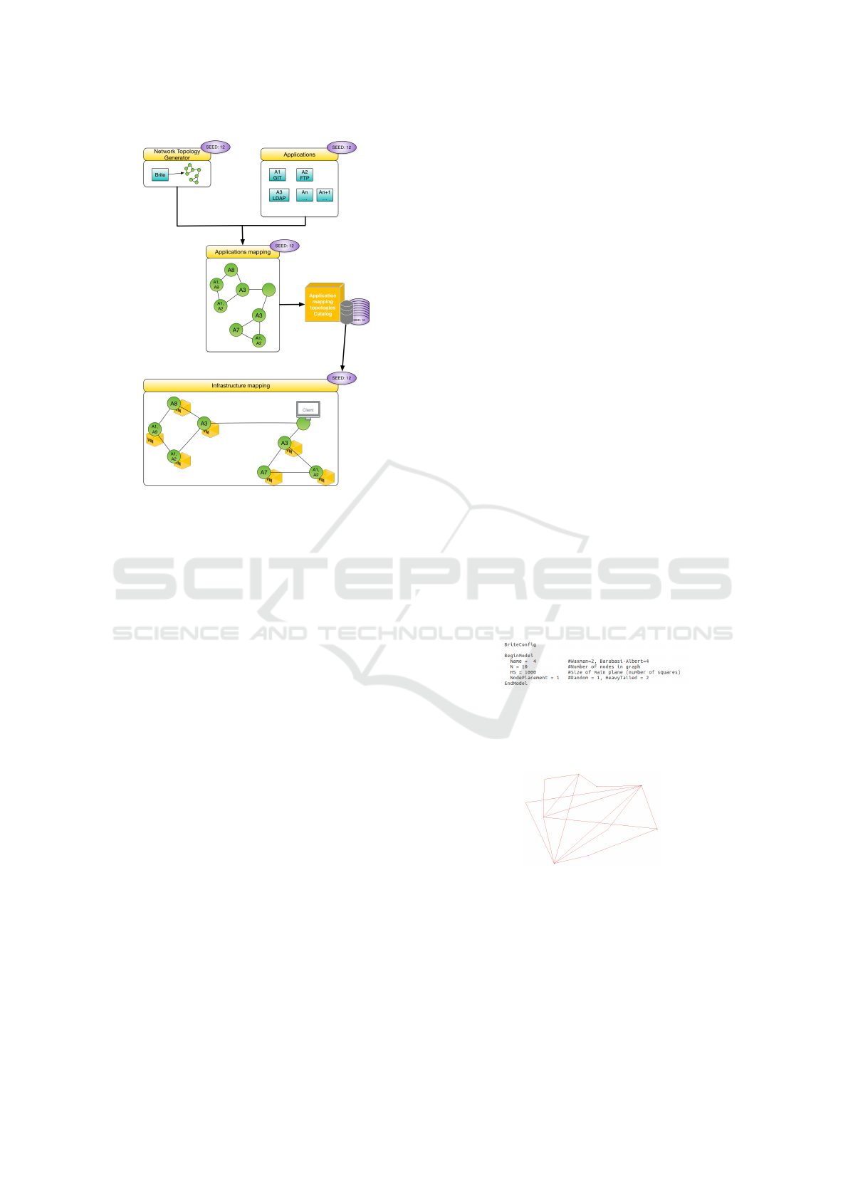
Figure 1: SeeDep architecture. The network topology gen-
erator builds a graph on which a set of applications is
mapped. The resulting application topology is identified
by a seed and stored in a catalog to ensure reproducibility.
Each application topology from the catalog can be deployed
on different infrastructures.
dom graph model, extended the Erdos-Renyi model
by adding links between two nodes depending on their
Euclidean distance.
The random graphs were a standard, until 1997
and the rise of a second class: the hierarchical
network topologies. Representing by the GT-ITM
tool (Calvert et al., 1997), these hierarchical topolo-
gies came from the discovery of a hierarchical struc-
ture on the Internet topology. Basically, a hierarchical
network topology consists of several levels composed
of many sets of randomly connected nodes. Each set,
belonging to a level (except the top level), is con-
nected to all sets belonging to the higher level.
In 1999, the Faloutsos paper (Faloutsos et al.,
1999) show that the Internet topology had some
power law properties. The most famous one is the
degree distribution of the nodes. Shortly, there are
few nodes with high degree and many nodes with poor
degree. Several generation methods based on power
laws have then arised: GLP (Bu and Towsley, 2002),
PLRG (Aiello et al., 2000). The most used model
remains the Barabasi method (Barab
´
asi and Albert,
1999) relying on two mainstays: incremental growth
and preferential attachment. Briefly, nodes are added
on a Cartesian plane one by one and are linked to
nodes with high degree. The power law methods re-
main the latest, the most used and the most represen-
tative network topology classes.
During the last decades, several network topology
generators have been built. Most of them implements
the different methods previously introduced. Though
it is not maintained anymore, Brite (Medina et al.,
2001) remains the most popular generator.It is im-
plemented under the GPL license, both in Java and
C++. Brite allows users to create large graphs (more
than 500K nodes) from all classes (random, hierar-
chical, power law) using a graphical user interface
or the command line API. More recently, in 2013,
FNSS (Saino et al., 2013) brings users with a python
library, allowing them to generate graphs of thousands
of nodes from the three classes. We can also cite
aSHIIP (Tomasik Joanna, 2012) providing a graphi-
cal interface to quickly generate graphs (less than 2s
for 5K nodes) from the three classes in a simple way.
SeeDep is built in a modular way so that many net-
work topology generators can be used. Thanks to its
popularity and simplicity, Brite is the network topol-
ogy generator used by default in SeeDep.
The Brite command line interface is used to gen-
erate a network topology. Two arguments are needed:
a configuration file specifying, among other, the used
model and the network topology size; and an output
file. Figure 2 represents a Brite configuration file used
for generating a network topology composed of 10
nodes based on the Barabasi model. The resulting
network topology is shown in Figure 3.
Figure 2: This Brite configuration file describes how to gen-
erate a network topology of 10 nodes. 10 nodes are ran-
domly placed in a 1000 × 1000 square and linked using the
Barabasi model.
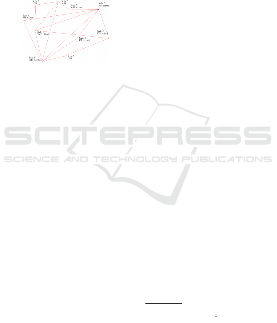
Figure 3: A network topology of size 10 built using the
Barabasi model implemented in Brite.
3.3 Application Topology
An application topology is a combination of two ele-
ments: a network topology and a set of applications.
Application topologies are used to describe experi-
ments set-up such as information about the network
SeeDep: Deploying Reproducible Application Topologies on Cloud Platform
365

topology, the topology size, the applications gener-
ating activities, . . . The following sections describe
the two application topology components and how to
combine them.
3.3.1 Applications
An application is a service that generates a network
activity (dataflows). This application can be either
a functional service (shared storage space, mail han-
dling, Voice over IP, . . . ) or a security service (fire-
wall, authentication, . . . ). For example, we may
deploy the following applications onto the network
topology built in the previous section: 1 FTP server;
2 LDAP; 1 VoIP; 3 FTP clients; 3 VoIP clients.
Since the application topologies are to be de-
ployed on Cloud platforms, that is on virtual ma-
chines, SeeDep assesses that to one application corre-
sponds one virtual environment. Thus, deploying an
application topology on a Cloud platform consists in
instantiating the Virtual Machines and deploying the
corresponding virtual environments on them.
3.3.2 Application Mapping
To get an application topology, the combination of the
two previous components (network topology and ap-
plications) is achieved by mapping the applications to
the nodes of the network topology. This mapping is
done following some user constraints (one application
per node, . . . ) called rules. Each rule consists of a set
of formulas in Conjunctive Normal Form (CNF). All
rules are processed using a SAT solver in order to pro-
vide an application mapping.
A CNF formula consists of a set of literals set to
false or true. In SeeDep, a literal represents: “this ap-
plication hosted on this node”. SeeDep, being written
in Python, relies on pycosat
4
to solve the rules. In
pycosat, a literal is represented by an integer. Conse-
quently, SeeDep’s Literal Representation (SLR) must
be transformed into Pycosat’s Literal Representation
(PLR).
To explain how to do that, let’s have an example.
We want to map the 10 previous applications on the
10 nodes of the network topology shown in Figure 3.
Each application is assigned with an id from 1 to 10,
as seen in Table 1. Each node is also assigned with an
id from 0 to 9. Using the formulas (1) and (2) we are
able to transform the SLR into PLR and vice versa.
For example, “application with id 3 hosted on node
with id 1” is transformed into 14, while 10 means “ap-
plication with id 10 hosted on node with id 0”.
4
https://pypi.org/project/pycosat/
Table 1: Applications Id assignment.
Apps Id
FTP server 1
LDAP 2
LDAP 3
VoIP 4
FTP client 5
FTP client 6
FTP client 7
VoIP client 8
VoIP client 9
VoIP client 10
PLR(node id,app id) = 11 ×node id +app id (1)
node id = PLR/11 (2)
app id = PLR%11
More generally, let’s assume A the set of appli-
cations to be mapped and N the set of nodes of the
network topology, PLR and SLR are processed using
formulas (3) and (4)
∀n ∈ N, a ∈ A,PLR(n,a) = (|A| + 1) × n + a (3)
n = PLR/(|A| + 1) (4)
a = PLR%(|A| + 1)
Finally, SeeDep rules are represented by CNF for-
mulas composed of PLR literals. For example, the
rule “one application per node” is represented by the
formulas in Table 2.
Table 2: CNF formulas representing the rule “one applica-
tion per node”.
One app on node 0 One app on node 1
(1 ∨ 2 ∨ . ..∨10) (12 ∨ 13 ∨ . ..∨21)
∧(¬1 ∨ ¬2) ∧(¬12 ∨ ¬13)
∧(¬1 ∨ ¬3) ∧(¬12 ∨ ¬14)
∧(...) ∧(...)
∧(¬8 ∨ ¬9) ∧(¬19 ∨ ¬20)
∧(¬9 ∨ ¬10) ∧(¬20 ∨ ¬21)
. . . One app on node 9
. . . (100 ∨ 101 ∨ . ..∨109)
. . . ∧(¬100 ∨ ¬101)
. . . ∧(¬100 ∨ ¬102)
. . . ∧(...)
. . . ∧(¬107 ∨ ¬108)
. . . ∧(¬108 ∨ ¬109)
Since pycosat provides results in PLR form, we
apply the formula (4) on literals that are set to true
CLOSER 2019 - 9th International Conference on Cloud Computing and Services Science
366
to map applications onto nodes as seen in Table 3.
The data structure (5) represents an application topol-
ogy (AT) and the resulting application mapping for
our example is representing by Figure 4.
AT = {(n,a)|∀n ∈ N,a ∈ A,PLR(n,a) = True} (5)
Figure 4: The application topology where applications from
Table 1 are mapped using the rule “one application per
node” on a graph of 10 nodes generating by Brite.
AT = {(0,1),(1, 2),... ,(8,9), (9, 10)}.
3.4 Reproducibility
User experiments results submitted in papers suffer
from a lack of information about how these experi-
ments were conducted. During last decades, many
studies have focused on reproducibility issues. Two
approaches can be distinguished: sensitization ap-
proach; and practical approach. Sensitization ap-
proach is about adopting good practices to provide
reproducible experiments. Authors are encouraged to
be transparent in their experiments and to share all rel-
evant experiments information such as source code,
data, workflows, and scripts for generating graph-
ics (Munaf
`
o et al., 2017; Allen et al., 2017). Practi-
cal approach concerns tools dedicated to ease the en-
forcement of good practices. These are public plat-
forms usually accessible from a web site, allowing
authors to share the code and data related to their pa-
pers (Austin et al., 2011). In addition to make code
and data available to others, (Gavish and Donoho,
2011; Koop et al., 2011) allow users to run the code
in the Cloud, while (Stodden et al., 2012; Gorp and
Mazanek, 2011) allow authors to share remote Vir-
tual Machines containing the experiments set-up. By
clicking on a link users can connect to these VMs.
On its side, SeeDep belongs to the practical ap-
proach. It avoids the lack of information by: associat-
ing a generation key, called a seed, to an application
topology; and storing this application topology into
a mongodb NoSQL database
5
. To one seed corre-
sponds one and only one application topology. Thus,
5
https://www.mongodb.com/
users can share their results along with the seed used
in their experiment, enabling other researchers to eas-
ily reproduce the experiment set-up.
Since our application topology example com-
posed of 10 nodes is the first one we have created,
we use the seed 1.10. We assign this seed to the data
structure AT in a MongoDB readable format:
{1.10 : {(0,1),(1,2), . . . , (9, 10)}}
3.5 Deployment
SeeDep aims at deploying reproducible application
topologies on real cloud platform. Many Cloud appli-
cations deployment framework exist, such as Cloud-
soft
6
or Cisco CloudCenter
7
, . . . ). However, we
choose to use Cloudify
8
described by its developers
as “the only open source model-driven cloud native
orchestration platform.”, and relying on a huge com-
munity working together to improve and add new fea-
tures. It allows to easily model applications and vir-
tual machines independently from the physical target
cloud platform. It relies on 2 mainstays: blueprints
for modeling applications; and plugins for interfacing
with physical cloud platform.
A blueprint is a kind of recipe, based on the OA-
SIS TOSCA (Topology Orchestration Specification for
Cloud Applications) standard (TOSCA, 2013). In a
TOSCA blueprint, users are able to describe not only
their applications (endpoints, lifecycle, dependencies,
. . . ) but also the virtual machines on which these
applications run (CPUs, memory, environment, . . . ).
Note that, an alternative to TOSCA may be the use
of OCCI (Nyren et al., 2016) aiming at standardizing
“an API for the management of any kind of cloud re-
sources.”. Figure 5 represents a part of the blueprint
modeling our topology application example built in
the previous sections.
Plugins are the components that link a blueprint to
a Cloud platform. They are responsible for transform-
ing applications description to their implementation.
How the virtual machines described in a blueprint are
instantiated on a Cloud platform? How the applica-
tions described in a blueprint are installed and run
on these virtual machines? Plugins answer to this
kind of question relying on two components: a plu-
gin blueprint; and a plugin source code. The plugin
blueprint acts as a “super” blueprint. It allows to de-
scribe the lifecycle of nodes type, that can be used in
classics blueprints. For example, Figure 6 describes
6
https://cloudsoft.io/
7
https://www.cisco.com/c/fr fr/products/cloud-systems-
management/cloudcenter/index.html
8
https://cloudify.co/
SeeDep: Deploying Reproducible Application Topologies on Cloud Platform
367
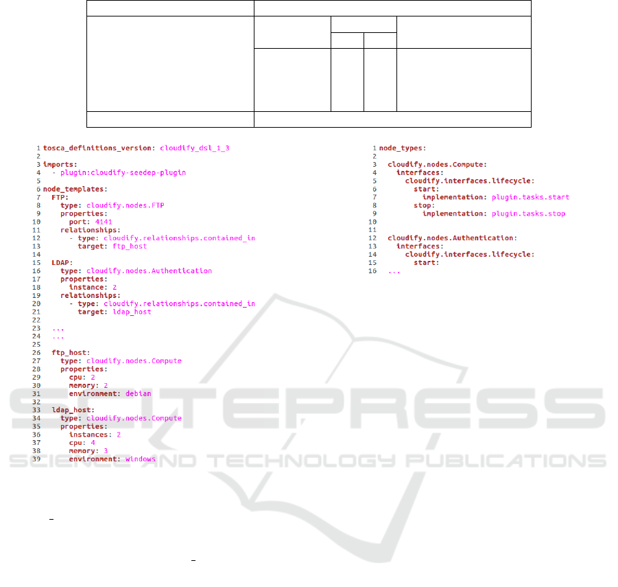
Table 3: Building an application topology from pycosat results.
Pycosat results 1 ∧ 13 ∧ . . . ∧ 109
PLR to SLR
PLR literal
SLR
Info
n a
1 0 1 FTP server on node 0
13 1 2 LDAP on node 1
. . . . . . . . . . . .
109 9 10 VoIP client on node 9
Applications topology (AT ) {(0,1),(1,2), . . . , (9,10)}
Figure 5: This piece of blueprint describes the applica-
tion topology associated with the seed 1.10. FTP applica-
tion runs on port 4141 and is hosted on a Compute node
called ftp host which is a VM composed of 2 cpus, 2 GB
of memory and running a debian environment. There are
2 instances of LDAP application. These applications are
hosted on Compute nodes called ldap host which are VM
composed of 4 cpus, 3 GB of memory and running a win-
dows environment.
the lifecycle of the cloudify.nodes.Compute node type
(Figure 5, lines 27 and 34). The plugin source code,
written in Python, implements the lifecycle of nodes
type. For example, the following code is a part of the
lifecycle start action of the cloudify.nodes.Compute
node type (Figure 6, lines 6-7).
@operation
def start(**kwargs):
# Get VM properties from the blueprint
cpu=ctx.node.properties[’cpu’]
memory=ctx.node.properties[’memory’]
env=ctx.node.properties[’environment’]
# Instantiate VM
cmd = "create_vm "+cpu+" "+memory+" "+env
Figure 6: Part of a plugin blueprint that defines the cloud-
ify.nodes.Compute lifecycle. Two lifecycle actions are de-
scribed: start and stop.
proc = subprocess.Popen([cmd],
stdout=subprocess.PIPE,
stderr=subprocess.STDOUT,
shell=True)
SeeDep is responsible for writing blueprints. Each
blueprint created by SeeDep fits to the target cloud
platform by importing the right plugin into the
blueprint import section (Figure 5, lines 3-4), and by
using the right node type (provided by the plugin) for
each application and virtual machine described in the
blueprint.
4 SeeDep USER API
The previous section has focused on technical details
about how to generate, reproduce and deploy an appli-
cation topology. These details are completely trans-
parent for the end-user. In this section, we introduce
the SeeDep command used to create, reproduce and
deploy an application topology.
To create an application topology (network exper-
iment set-up), we proceed in three steps:
• give information (name, number of instances)
about the applications to be deployed;
• give information (name) about the mapping rules
to be applied;
• create the application topology associated with a
seed.
The following commands are run to achieve these
steps:
CLOSER 2019 - 9th International Conference on Cloud Computing and Services Science
368

$ seedep edit apps App_Name:App_Instance ...
$ seedep edit rules Rule_Name ...
$ seedep create <seed>
To reproduce a network experiment set-up, we re-
generate the corresponding application topology be-
longing to the catalog of application topologies (see
Section 3) using its seed. We also make this applica-
tion topology suitable to the deployment target Cloud
platform. The following command is run to achieve
the reproduction:
$ seedep gen deploy <seed> <platform>
Finally, to deploy on a Cloud platform an applica-
tion topology associated with a seed, we proceed in
three steps:
• configure the deployment environment (Cloudify
and Cloud platform requirements);
• deploy the application topology on a Cloud plat-
form;
• get information about applications endpoints (ip
addresses, hostnames).
The following commands are run to achieve these
steps:
$ seedep gen env <seed> <platform>
$ seedep deploy <seed> <platform>
$ seedep gen info <seed> <platform>
Let’s have an example. A researcher wants to
evaluate his new intrusion detection algorithm. He
wants to perform a network experiment that can be re-
produced by other researchers. Using SeeDep, he will
create the application topology (experiment set-up)
1.10 composed of 10 nodes (Figure 3) and 10 applica-
tions (Table 1) mapped using the rule RoO (standing
for Rule of One, that is, “one application per node”):
$ seedep edit apps FTPserver:1 ... VoIPclient:3
$ seedep edit rule RoO
$ seedep create 1.10
Once the application topology is created, the re-
searcher runs his experiment and shares his results to
the community along with the seed 1.10.
As reviewers, we want to reproduce this network
experiment and verify the results. We plan to de-
ploy the experiment on two different Cloud plat-
forms: OpenStack
9
and Triton
10
. Using SeeDep, we
are able to reproduce the application topology corre-
sponding to this experiment and deploy it on Open-
Stack and Triton platforms:
$ seedep gen deploy 1.10 openstack
$ seedep gen env 1.10 openstack
$ seedep deploy 1.10 openstack
9
https://www.openstack.org/
10
https://www.joyent.com/
$ seedep gen info 1.10 openstack
$ seedep gen deploy 1.10 triton
$ seedep gen env 1.10 triton
$ seedep deploy 1.10 triton
$ seedep gen info 1.10 triton
5 CONCLUSIONS
As computer networks become more accessible and
pervasive, more and more research areas rely on com-
puter networks experiments. Along with this diver-
sity, reproducibility issues arise. As part of the sci-
entific method, any researcher in the world should
be able to reproduce the experimentation in order to
verify the result. Unfortunately, experiments results
shared in a paper conference are not often submitted
along with information related to the experiment set-
up. In this paper, we have proposed SeeDep a frame-
work aiming at being a standard tool for generating,
reproducing and deploying experiments set-up called
application topology.
SeeDep relies on an algorithm that generates
experimentation networks, and a seed that can be
shared which specifies the said network. It is com-
posed of 4 modules and 7 commands. The net-
work topology generator and the application topol-
ogy modules, associated with seedep edit apps,
seedep edit rules and seedep create deploy
commands, allow for creating a catalog of appli-
cation topologies. The reproducibility module, as-
sociated with seedep gen deploy, allow for re-
generating any application topology belonging to
the catalog. Finally, the deployment module asso-
ciated with seedep gen env, seedep deploy and
seedep gen info, allow for deploying an applica-
tion topology on different Cloud platforms.
Seedep likes to be modular. Different network
topology generators or different SAT solvers can be
used. Similarly, different Cloud platforms can be used
for the deployment. For these reasons, achieving a
SeeDep performance evaluation makes no sense and
is out of scope.
For future works, we plan to implement consis-
tency rules for applications mapping. For example,
a FTP server must be mapped on a node connected
to ones that can use it (nodes with FTP clients). A
firewall, filtering input and output traffic, must not
be placed on an isolated node (node with only one
link). These rules may lead to huge CNF formulas
and running a SAT solver can take a while. Using an
hybrid approach, with a SAT solver giving a quick
approximating solution completed using heuristics,
can help for having suitable solution in a reasonable
SeeDep: Deploying Reproducible Application Topologies on Cloud Platform
369

time. SeeDep will also be used for deploying cyber
attacks simulations. Consequently, implementing be-
havioral agents to generate realistic traffic, workflows
and dataflows is also investigated.
REFERENCES
Aiello, W., Chung, F., and Lu, L. (2000). A random graph
model for massive graphs. In Proceedings of the
thirty-second annual ACM symposium on Theory of
computing, pages 171–180. Acm.
Allen, A., Aragon, C., Becker, C., Carver, J., Chis, A.,
Combemale, B., Croucher, M., Crowston, K., Garijo,
D., Gehani, A., Goble, C., Haines, R., Hirschfeld, R.,
Howison, J., Huff, K., Jay, C., Katz, D. S., Kirchner,
C., Kuksenok, K., L
¨
ammel, R., Nierstrasz, O., Turk,
M., van Nieuwpoort, R., Vaughn, M., and Vinju, J. J.
(2017). Engineering Academic Software (Dagstuhl
Perspectives Workshop 16252). Dagstuhl Manifestos,
6(1):1–20.
Austin, J., Jackson, T., Fletcher, M., Jessop, M., Liang,
B., Weeks, M., Smith, L., Ingram, C., and Watson, P.
(2011). Carmen: Code analysis, repository and mod-
eling for e-neuroscience. Procedia Computer Science,
4:768 – 777. Proceedings of the International Confer-
ence on Computational Science, ICCS 2011.
Barab
´
asi, A.-L. and Albert, R. (1999). Emergence of scal-
ing in random networks. science, 286(5439):509–512.
Bu, T. and Towsley, D. (2002). On distinguishing between
internet power law topology generators. In INFO-
COM 2002. Twenty-First Annual Joint Conference of
the IEEE Computer and Communications Societies.
Proceedings. IEEE, volume 2, pages 638–647. IEEE.
Calvert, K. L., Doar, M. B., and Zegura, E. W. (1997). Mod-
eling internet topology. IEEE Communications mag-
azine, 35(6):160–163.
Donoho, D. L., Maleki, A., Rahman, I. U., Shahram, M.,
and Stodden, V. (2009). Reproducible research in
computational harmonic analysis. Computing in Sci-
ence Engineering, 11(1):8–18.
Erdos, P. and Renyi, A. (1960). On the evolution of random
graphs. Publ. Math. Inst. Hungary. Acad. Sci., 5:17–
61.
Faloutsos, M., Faloutsos, P., and Faloutsos, C. (1999). On
power-law relationships of the internet topology. SIG-
COMM Comput. Commun. Rev., 29(4):251–262.
Gavish, M. and Donoho, D. (2011). A universal identifier
for computational results. Procedia Computer Sci-
ence, 4:637 – 647. Proceedings of the International
Conference on Computational Science, ICCS 2011.
Gorp, P. V. and Mazanek, S. (2011). Share: a web portal for
creating and sharing executable research papers. Pro-
cedia Computer Science, 4:589 – 597. Proceedings of
the International Conference on Computational Sci-
ence, ICCS 2011.
Hutchinson, J. (2001). Culture, communication, and an in-
formation age madonna. IEEE Professional Commu-
nication Society Newsletter, 45:1–7.
Jin, C., Chen, Q., and Jamin, S. (2000). Inet: Internet topol-
ogy generator.
Koop, D., Santos, E., Mates, P., Vo, H. T., Bonnet, P., Bauer,
B., Surer, B., Troyer, M., Williams, D. N., Tohline,
J. E., Freire, J., and Silva, C. T. (2011). A provenance-
based infrastructure to support the life cycle of exe-
cutable papers. Procedia Computer Science, 4:648 –
657. Proceedings of the International Conference on
Computational Science, ICCS 2011.
LeVeque, R. J. (2009). Python tools for reproducible re-
search on hyperbolic problems. Computing in Science
Engineering, 11(1):19–27.
Medina, A., Lakhina, A., Matta, I., and Byers, J. (2001).
Brite: An approach to universal topology generation.
In Modeling, Analysis and Simulation of Computer
and Telecommunication Systems, 2001. Proceedings.
Ninth International Symposium on, pages 346–353.
IEEE.
Munaf
`
o, M. R., Nosek, B. A., Bishop, D. V. M., Button,
K. S., Chambers, C. D., Percie du Sert, N., Simon-
sohn, U., Wagenmakers, E.-J., Ware, J. J., and Ioan-
nidis, J. P. A. (2017). A manifesto for reproducible
science. Nature Human Behaviour, 1(1):0021+.
Nsnam (2006). Topology Generator - nsnam.
http://www.eg.bucknell.edu/
∼
perrone/research-docs/
NSFProjectDescription.pdf. Accessed: 2018-11-26.
Nyren, R., Edmonds, A., Papaspyrou, A., Metsch, T., and
Parak, B. (2016). Open cloud computing interface -
core. http://ogf.org/documents/GFD.221.pdf.
Saino, L., Cocora, C., and Pavlou, G. (2013). A toolchain
for simplifying network simulation setup. In Pro-
ceedings of the 6th International ICST Conference on
Simulation Tools and Techniques, SIMUTOOLS ’13,
ICST, Brussels, Belgium, Belgium. ICST.
Stodden, V., Hurlin, C., and P
´
erignon, C. (2012). Run-
mycode.org: A novel dissemination and collabora-
tion platform for executing published computational
results. In 2012 IEEE 8th International Conference
on E-Science, pages 1–8.
Tomasik Joanna, W. M.-A. (2012). The inter-domain hi-
erarchy in measured and randomly generated as-level
topologies. In IEEE International Conference on
Communications (ICC), Otawa, Canada.
TOSCA (25 November 2013). Topology and orches-
tration specification for cloud applications version
1.0. http://docs.oasis-open.org/tosca/TOSCA/v1.0/os/
TOSCA-v1.0-os.html. OASIS Standard.
Waxman, B. M. (1988). Routing of multipoint connections.
IEEE journal on selected areas in communications,
6(9):1617–1622.
CLOSER 2019 - 9th International Conference on Cloud Computing and Services Science
370
