
Introducing B-Sequenced Petri Nets as a CPN Sub-class for Safe Train
Control
Zakaryae Boudi
1
, Abderrahim Ait Wakrime
2 a
, Simon Collart-Dutilleul
3
and Mohamed Haloua
1
1
Ecole Mohammadia d’Ing
´
enieurs, Med V University, Rabat, Morocco
2
Institut de Recherche Technologique Railenium, F-59300, Famars, France
3
IFSTTAR-Lille, 20 Rue Elis
´
ee Reclus BP 70317, 59666 Villeneuve d’Ascq Cedex, France
simon.collart-dutilleul@ifsttar.fr, haloua@emi.ac.ma
Keywords:
B-Sequenced Petri Nets, Colored Petri Nets, B Method, Railway Safety, ERTMS/ETCS.
Abstract:
Formalizing system specification has been highly valuable in demonstrating safety and consistence of safety
critical systems. It is undoubtedly the case in railway signalling, especially the European Rail Traffic Man-
agement System/European Train Control System (ERTMS/ETCS). However, the complexity of the European
standard specification, especially for its highest level, namely level 3, requires a significant overtake in early
modelling approaches when it comes to clearly expressing system functionalities along with safety require-
ments, all towards a concrete safe design. In this regard, our research introduces a Colored Petri net (CPN)
sub-class associated to an Event-B machine and annotated by mathematical sequences, which are ex-pressed
in the B-language, all in the view of enriching the modelling techniques intended for system formal specifi-
cation and verification. In this paper, we show through a detailed ERTMS L3 case study, how such featured
CPNs fit in the progressive formalization and verification of Movement Authority (MA) computation.
1 INTRODUCTION AND
RELATED WORK
Today’s industrial systems in transport, energy,
healthcare or aerospace tend to involve big amounts of
automation, growing quantities of data and unprece-
dented connectivity sophistication. But they are not
without bringing more complexity and unprecedented
technical challenges as both technologies and user ex-
pectations evolve so quickly. In an era where the mas-
ter words are artificial intelligence, big data, internet
of things or analytics, industrial systems’ providers
and end users are increasingly concerned about over-
seeing quality standards, safety and security.
More specifically, computing power and software-
development techniques have made train control func-
tions better performing and less costly than before.
For ex-ample, while rail signalling once had to be
analogically connected to electronic relays, with ded-
icated wiring through tracks and signals, they now
use totally computer-based technologies in which sig-
nalling can be performed using virtual algorithms and
wireless communication. This is the case for the Eu-
a
https://orcid.org/0000-0001-9215-6309
ropean Rail Traffic Management System (ERTMS)
we will address in this paper, where movements are
intended to be automatically computed and moni-
tored through an on-board or track-side control sys-
tem, greatly reducing setup time. What is challeng-
ing though with the ERTMS standard is to build at
the same time safe-by-design and fully specification-
consistent software train control solutions. With the
available technological potential, how do engineers
decide on the best development strategy, the one that
costs less, takes acceptable time to implement, and
delivers the specification objectives? One approach
to handle such an endeavour is formalizing specifica-
tions by the use of mathematical representations.
Indeed, with the advance in technology over the
past decades came the first use of mathematical tools
to produce safe-by-design automation. But in fact,
technology is only one of many reasons that brought
mathematics in scope. Changes in regulation towards
a more demanding safety and quality requirements -
including need for certification and accreditation - put
formal analysis in the core of system and software de-
velopment. Also, using mathematical models means
that more of the development and validation work
can be automated, and thus, provided with reduced
350
Boudi, Z., Ait Wakrime, A., Collart-Dutilleul, S. and Haloua, M.
Introducing B-Sequenced Petri Nets as a CPN Sub-class for Safe Train Control.
DOI: 10.5220/0007725103500358
In Proceedings of the 14th International Conference on Evaluation of Novel Approaches to Software Engineering (ENASE 2019), pages 350-358
ISBN: 978-989-758-375-9
Copyright
c
2019 by SCITEPRESS – Science and Technology Publications, Lda. All rights reserved

costs. For example, one early interesting application
of formal methods has been the development of tools
able to generate comprehensive test cases from formal
specifications (Toth et al., 1996). Theorem proving of
systems meeting their specification is another, more
recent, cost saving and effective use of formal meth-
ods in the verification and validation process (Richard
et al., 2002). To sum up, at their heart, formal meth-
ods come to apply software based mathematical mod-
elling on industrial systems in order to help demon-
strate they meet their specifications, quality and safety
properties. But that tells only a small part of the story.
Many other cases involve formal methods, in many
different ways, to build a sound understanding of sys-
tems’ functioning and interactions, validate data be-
fore commissioning, generate test cases and reduce
the overall development costs (Ait Wakrime et al.,
2014).
The present research suggests that bridging differ-
ent formal techniques, particularly for use during the
specification and verification phases, can contribute
to creating more diverse and agile design frameworks,
and providing purpose-built solutions to safely handle
system design. This paper’s contribution falls in the
Petri nets sub-classes research line and can be viewed
as completing the development of the re-search ex-
ploring the transformation of Petri nets to Event-B
and Classical-B (Boudi et al., 2017; Boudi et al.,
2015), by introducing what we call B-sequenced
CPNs, a CPN sub-class. These aim to broaden the
features of Petri nets using mathematical sequences
annotations as expressed in the B-language, and B-
method verification tools as a mean to enhance mod-
elling accuracy and the overall model design, verifi-
cation and validation. Of course, several sub-classes
of Petri nets have been proposed in the literature, of
which we cite as example (Chiola and Franceschinis,
1989; Ait Wakrime, 2015), which focused on improv-
ing fineness in modelling the behaviour of systems.
However, none of the existing contributions have cov-
ered the merger of other formal methods’ features in a
Petri net sub-class, whether it is in view of consolidat-
ing correctness verification of the formal specification
or for creating a bridge to formal model refinement to-
wards safe-by-design code generation.
In considering all these, we will explain and show
in this paper, through an ERTMS level 3 case study
addressing the design of safe Movement Authority
(MA) control, how such a sub-class of colored Petri
nets, combining B-method notations and the concepts
of mathematical sequences, fits in a progressive solu-
tion formalization and verification. After introducing
the used definitions of Colored Petri nets (CPNs), and
qualifying general aspects surrounding the B-method,
the next parts will introduce the suggested CPNs’
sub-class. On this basis, the following sections will
provide a detailed case study where a concrete ap-
plication of B-sequenced CPNs is shown, including
modelling and validating the railway ERTMS Level 3
Movement Authority computation.
2 AN OVERVIEW OF PETRI
NETS
Carl Adam Petri, German mathematician and com-
puter scientist, developed the mathematical networks
commonly known as Petri nets between 1960 and
1962. Petri nets became initially famous in the scope
of the MIT Project on Mathematics and Computa-
tion (MAC project) in the 1970s. The main bene-
fit from these Petri networks is the thorough design
and analysis of a wide variety of discrete event sys-
tems. They enable both static and dynamic modelling
through their structure and operating rules.
A Petri net is a graph containing two types of
nodes. First, “places” that are graphically represented
by circles, empty or containing tokens, and second,
“transitions” as bars or boxes. “Places” and “transi-
tions” connect to each other via directed arcs. These
arcs can only link a “place” to a “transition” or a
“transition to a place”, and “transitions” are enabled
when there is a token in the input “places”. Moreover,
a Petri net must have an initial state also called initial
marking. Detailed explanation is provided in (Murata,
1989). While place/transition Petri nets seem to be
well suited for small size discrete systems, it is clear
they might raise many limitations when dealing with
big complex systems, such as railways or smart grids.
One alternative to easily design more complex sys-
tems is to use High-level Petri nets.
Tokens cannot be distinguished in elementary
Petri nets. Nevertheless, real systems’ design requires
the possibility of transforming the nature of tokens
through a “transition”. This is why High-level Petri
nets appeared as a new type of Petri nets which cope
with token transformation and support a first-order
language. A first class of High-level Petri nets known
as the “predicate/transition” nets was introduced by
Hartmann Genrich (Jensen and Rozenberg, 2012),
followed by Algebraic Petri nets (Reisig, 1991), and
later the development of colored Petri nets by Kurt
Jensen (Jensen, 2013). In brief, Colored Petri nets
(CPNs) are an extension of Petri nets where the main
strength lies in the use of a functional language that is
based on the notion of typing. They accordingly link
each token to a type called “colour” which differenti-
ates tokens. Below Kurt Jensen’s formal definition of
Introducing B-Sequenced Petri Nets as a CPN Sub-class for Safe Train Control
351

a colored Petri net:
Definition 1. A colored Petri net is a tuple CPN =
(Σ, P, T, A, N, C, G, E, I) satisfying the following re-
quirements:
• Σ is a finite set of non-empty types, called colour
sets.
• P is a finite set of places.
• T is a finite set of transitions.
• A is a finite set of arcs such that: P ∩T = P ∩ A =
T ∩ A = ∅.
• N is a node function. It is defined from A into
P × T ∪ T × P.
• C is a colour function. It is defined from P into Σ.
• G is a guard function. It is defined from T into
expressions such that: ∀t ∈ T : [Type(G(t)) =
Bool ∧ Type(Var(G(t))) ⊆ Σ].
• E is an arc expression function. It is defined
from A into expressions such that: ∀a ∈ A :
[Type(E(a)) = C(p(a))
MS
∧ Type(Var(E(a))) ⊆
Σ]. Where p(a) is the place of N(a).
• I is an initialization function. It is defined from
P into closed expressions such that: ∀p ∈ P :
[Type(I(p)) = C(p)
MS
].
To have more details on the above definition, the
reader can refer to [11].
CPN-tools is one of the most advanced existing
platforms for editing colored Petri nets. Architected
by Kurt Jensen, Soren Christensen, Lars M. Kris-
tensen, and Michael Westergaard (Jensen et al., 2007;
Ratzer et al., 2003), it combines colored Petri nets
with the “Standard ML” functional programming lan-
guage. Standard ML enables the definition of data
(i.e. places, transitions, colours, variables, etc.) types
as well as the corresponding algorithms. Many re-
search projects have adopted CPN-tools for the avail-
ability of references and its common use in literature.
3 B METHOD AT A GLANCE
The B-method is a formal method -including theory,
the modelling language and tools- that allows math-
ematical specification and strict formulation of in-
variant properties related to the design and function-
ing of a given system. It covers the whole system
development life cycle, from specification to imple-
mentation. Automatic and/or manual mathematical
proof is accordingly possible to demonstrate that the
desired properties coherently hold during operations.
Initially designed by Jean-Raymond Abrial as a the-
ory (Abrial, 2010; Abrial, 2005), the B-method found
several industrial applications, mainly in rail systems
such as the automatic control system of Paris metro
line 14 (Behm et al., 1999), the automation of Paris
line 1 by the RATP, and various other recent railway
developments worldwide.
The key B-method activities in a project lie in the
development of mathematical texts describing sys-
tems’ architecture, operations and properties, and the
formal proof applied on them. In practice, B-method
concepts are based on first-order logic mathematical
notations and the theory of sets, where the model is
structured as abstract representations, which are cor-
related with each other and called “machines”, “re-
finements” and “implementations”. Meanwhile, both
structural and dynamic characteristics can be repre-
sented using mathematical sets, constants, properties
and variables that evolve in respect to a number of
operations, starting from a specified initial state.
3.1 Mathematical Notation and
Abstract Machines
Mathematical notation in the B-method refers to the-
ory of sets and predicate logic, where a defined syn-
tax is used to describe operations, relations between
machines, refinements, and implementations. The
main B-language reference is Jean-Raymond Abrial’s
B Book [14]. In effect, properties are expressed by
formulas of first order predicate calculus, constructed
with conventional propositional operators such as (∧),
(∨), universally quantification (∀) or existentially (∃)
quantified variables.
As already said, one major notion of the B-method
are abstract machines. Specifically, abstract machines
can be considered as a form of imperative program-
ing, which sets operations as a sequence of elemen-
tary instructions willing to change the program state
when executed. Each machine has its own variables
and operations, and variables can only evolve through
their machine’s operations.
3.2 Tools in Focus: ProB and Atelier-B
Let’s not forget that the success of B-method in indus-
try is highly driven by the existence of comprehen-
sive tools for automatic proof and model checking.
The most known ones are ProB , animator and model
checker of abstract machines, and Atelier-B , IDE and
theorem prover. Many major industry players such as
Siemens, Alstom, SNCF and RATP use these tools
as part of their systems development. At this point,
it might be instructive to distinguish between ProB
and Atelier-B features. On the one hand, ProB al-
lows fully automatic animation of B specifications
and can is used to systematically detect early model
ENASE 2019 - 14th International Conference on Evaluation of Novel Approaches to Software Engineering
352

errors and deadlocks. Model checking explores the
state-space and checks all states respect the specified
properties. In this respect, one of the main interests
of ProB is that the model checker returns a counter-
example when a property is violated.
On the other hand, Atelier-B is an industrial tool
which comprises an IDE and theorem prover and is
intended for an operational use of the B-method to
develop defect-free systems and software. The tool
had a decisive role in developing safety automatisms
for various worldwide subways, and also for several
certifications and the system modelling by ATMEL
and STMicroelectronics. What’s more, it has been
used in other sectors including the automotive indus-
try for cars onboard electronics. Unlike model check-
ing, theorem provers do not rely on exploring finite
state spaces. Although they are less simple to use
than model checkers, they have a stronger value in
bringing proof of correctness in light of mathematical
proving principles.
4 INTRODUCING B-SEQUENCED
CPNS
4.1 Sequences in the B-method
Before going further, it is important to clearly under-
stand what definition it will be referred to when deal-
ing with sequences in the B-method and all over this
paper. First, let us remind that, intuitively, a mathe-
matical sequence is representing an ordered list of the
elements of a finite or infinite set. In this paper, we
will consider the following definition with regards to
the B-method.
Definition 2. In the B method, a sequence whose ”el-
ements” belong to a set S is a total function of an in-
terval 1..n in S, where n ∈ N. The elements of the se-
quence correspond to the second elements of the pairs
of this function, and they are ordered by the first ones.
In the following definition of this paper, we will re-
fer to S as the base colour set, and [S] the sequence
1..n → S, where n = card(S).
4.2 B-sequenced CPNs
B-Sequenced CPNs refer to a particular structure of
CPNs which is associated to an Event-B machine and
allows the CPN model elements to be annotated with
B-language sequence expressions. Such a CPN is in-
tended to support both mathematical modelling and
proof of properties through B capabilities and tools.
In the CPN model, all places have a B-sequence type,
i.e. NATURAL → S, where S is a pre-defined finite
set.
Definition 3. We formally define a B-Sequenced
CPN as a tuple Bseq
CPN = (Σ, P, T, A, N, C, G, E, I),
which is derived from Jensen’s CPNs formal defini-
tion and associated to an Event-B machine such as:
• Σ is a finite set, representing the base color set and
corresponding to the set Color Σ under the clause
SETS of the Event-B machine.
MACHINE Bseq_CPN
SETS
color Σ = s1, ..., sn
• P is a finite set of places of type Seq Σ, such that:
DEFINITIONS
Seq Σ = [s1, ..., sn]
and for each p ∈ P, we have:
VARIABLES
State_p
INVARIANT
State
p
: NATURAL 7→ colorΣ
• T is a finite set of transitions, such that for each
t ∈ T , there is a B event corresponding to the firing
of t:
EVENTS
t
• A is a finite set of arcs such that: P ∩T = P ∩ A =
T ∩ A = ∅.
• N is a node function. It is defined from A into
P × T ∪ T × P.
• C is a color function. It is defined as C(P) =
Seq Σ.
• G is a guard function. It is defined from T into
expressions such that: ∀t ∈ T : [Type(G(t)) =
Bool ∧ Type(Var(G(t))) ⊆ Seq Σ].
• E is an arc expression function. It is defined
from A into expressions such that: ∀a ∈ A :
[Type(E(a)) = C(p(a))
MS
]∧ Type(Var(E(a))) ⊆
Seq Σ] and ∀t ∈ T, ∀a
0
∈ A provided that a
0
is an
output arc of t:
EVENTS
t = SELECTG(t) ∧ State p
0
(a)
THEN State p
00
(a) := E(a
0
)
END
Where p(a) is the place of N(a), p
0
(a) is the place
of N(a) ∩ P × T , and p
00
(a) is the place of N(a) ∩
T × P.
Introducing B-Sequenced Petri Nets as a CPN Sub-class for Safe Train Control
353

• I is an initialization function. It is defined from
P into closed expressions such that: ∀p ∈ P :
[Type(I(p)) = C(p)
MS
].
5 CASE STUDY: ERTMS L3 MA
COMPUTATION
5.1 Description
Although advanced autonomous train driving applica-
tions, especially ERTMS level 3, are still in their early
days, railway companies and industrial players realize
that they could become the main feature of future train
driving technology. ERTMS L3 solutions are now a
major focus of research and development, both at pri-
vate technology suppliers and open academic research
laboratories, in order to identify new approaches to
software projects focused on safety, security and tack-
ling complexity.
Figure 1: ERTMS/ETCS level 3 case description.
Let us remind that ERTMS, the European Rail
Traffic Management System, is comprised of ETCS
(European Train Control System) and GSM-Railway
(GSM-R). A broad description would refer to ERTMS
as a railway signalling system intended to safe rail
traffic control-command, which is rooted on interop-
erable technology and operating rules, with the ulti-
mate goal of guaranteeing uninterrupted train move-
ment across European territories.
In this paper, we consider only ETCS as we deal
with the control part of ERTMS. ETCS architec-
ture is outlined in the System Requirement Specifi-
cation (SRS) of the European Union Agency for Rail-
ways (Behm et al., 1999). What about GSM-R? It is
the radio protocol used for communications between
the trackside and the on-board equipment. Note that
GSM-R may however be abandoned to a new and
more suitable protocol in the coming years.
The three levels are some of the basic concepts of
the ERTMS/ETCS system. A short definition of each
one could be given as follows (UNISIG, 2006):
• Level 1: provides continuous supervision of train
movement with a discontinuous communication
between the trackside and the train by means of
balises installed in the tracks. Signals are neces-
sary for this level and train detection is performed
by track-circuits, out of the scope of ERTMS.
• Level 2: provides continuous supervision of train
movement with a continuous and bi-directional
communication provided by GSM-R. Signals are
optional for level, and train detection is performed
by track-circuits, out of the scope of ERTMS.
• Level 3: provides continuous supervision with
continuous bi-directional train/trackside commu-
nication. The difference with level 2 is that train
location and integrity are managed by the ERTMS
system. This means there is no need for side sig-
nals or track-circuits detection
In addition to those, there are two more levels
defined as level 0, referring to trains equipped with
ETCS but running on non-equipped lines, and level
STM, referring to trains equipped with ETCS running
on lines where another control system is operated. To
sum-up, in our case of ERTMS level 3, the transmis-
sion of information is done through radio, and train
detection and verification of integrity are performed
by the ERTMS/ETCS system (UNISIG, 2006). The
Movement Authority (MA), which is the focus of this
case, is calculated without track-side signals or phys-
ical circuits.
Next, we assume for our MA computation that
train detection circuits can be divided into several vir-
tual blocks called Virtual Sub-Sections (VSSs). The
MA is accordingly defined as the ordered set of free
virtual blocks ahead of the train, upon which the train
is authorized to move. The state (occupied or free)
of a VSS is determined on both reported train posi-
tion and trackside train detection. On this basis, the
purpose of this case is to formally design a safe com-
putation solution of the MA.
Running on the on-board equipment, the MA al-
gorithm will use the input from train sensors to syn-
thesize the surrounding environment in real-time (free
and occupied VSSs). The algorithm will then con-
clude what VSSs should intervene in the next MA.
Of course, this requires a proven safe-by-design ap-
proach, since any decisions that the algorithm speci-
fies is critical to ensuring safety. Note that this is a
simplified case with a number of unreal assumptions,
with a practical interest to showcase B-sequenced
CPN modelling and verification. Real life MA com-
putation is undoubtedly more complex and requires
highly sophisticated algorithms that a research paper
cannot cover exhaustively.
Concretely, we assume two trains are circulating
on a six virtual blocks track (Figure 1), and that, for
each computation cycle, trains can only move ahead
by one VSS distance (one step), if and only if the
ENASE 2019 - 14th International Conference on Evaluation of Novel Approaches to Software Engineering
354
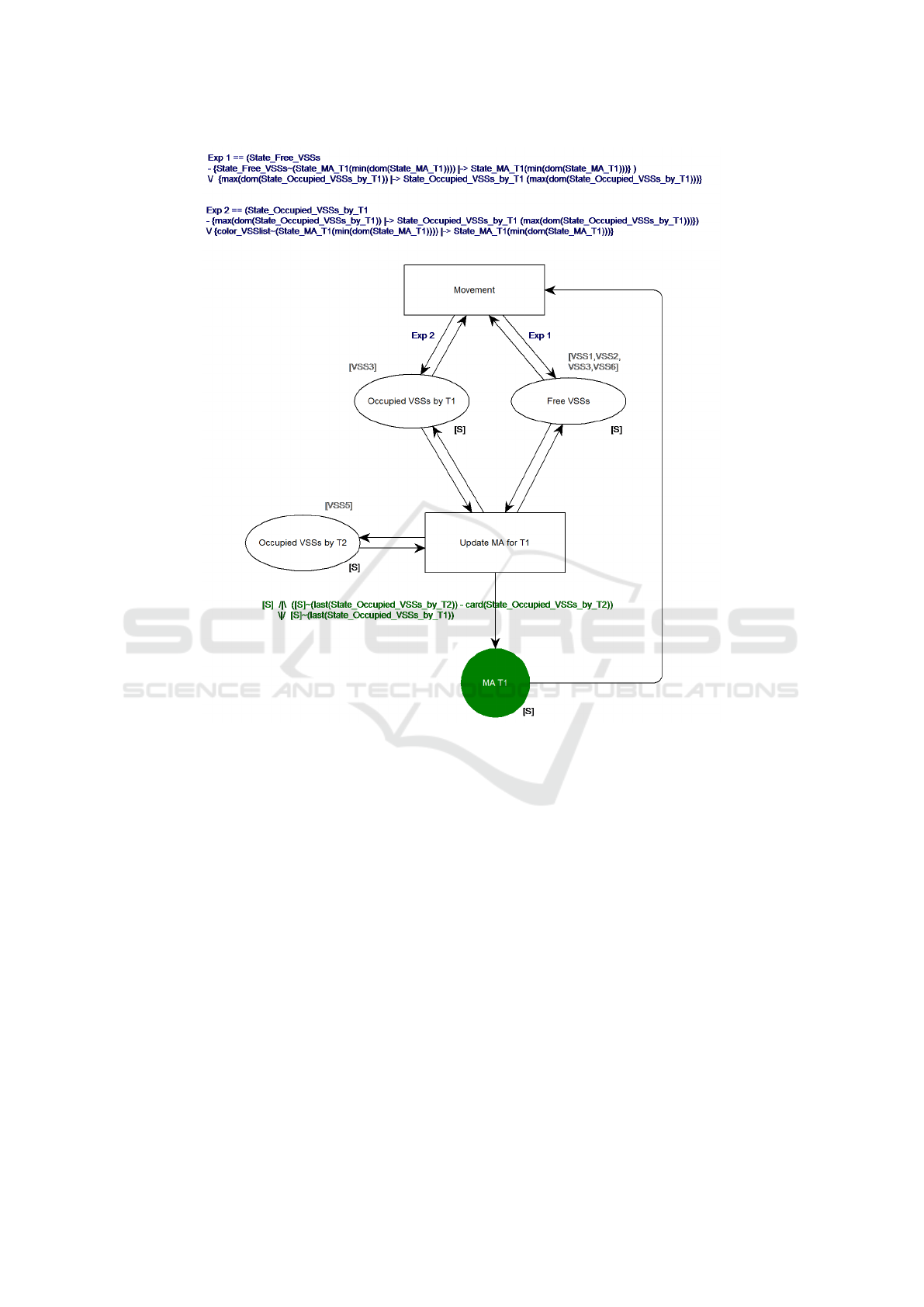
Figure 2: Movement Authority (MA) B-Sequenced CPN model.
MA is not empty. It is provided that for each cy-
cle, train 1 can measure its own position as well as
receive train 2 position. The system requires a safe
software function that computes train 1’s MA in any
possible configuration. Mathematically, we can con-
sider that the MA is a subsequence of the sequence
{VSS1,VSS2,VSS3,VSS4,VSS5,VSS6}, where the
elements have orders between the VSS occupied
by the head of Train 1 and the VSS occupied
by the tail of Train 2. For example, if we
consider the initial state in Figure 1, the MA
should be obtained by excluding VSS1, VSS2,
VSS4, VSS5 and VSS6 from the overall sequence
{VSS1,VSS2,VSS3,VSS4,VSS5,VSS6}, leaving an
MA = {VSS3}.
5.2 The B-sequenced CPN Model
At this stage, we design a B-sequenced CPN model
so that we have a safe-by-design MA at each cy-
cle. We will then demonstrate that it can make the
right decisions in all configurations using the feature
of B-sequenced CPNs we defined earlier in this pa-
per. The model is constructed as in Figure 2. Un-
like the fully programmatic techniques, B-sequenced
CPN models make it easier to carry a graphical rep-
resentation of our solution, from system inputs to fi-
nal outputs, all with B annotations for expressions
in guards and arcs. In effect, the model in Figure 2
contains three “places” representing the inputs of the
suggested MA algorithm, which are the state of occu-
pation of VSSs by Train 1 and Train 2, and the rest
of VSSs that are free. As an output, the transition
“Update MA for T1” and system of “arcs” calculates
the set of VSSs representing the MA, and fills it ac-
cordingly in the green place “MA T1”. We notice
that, in accordance of the definition of B-sequences
CPNs, all places have a B-sequence type noted [S],
i.e. NATURAL → S, where S is a pre-defined finite
set equal to {VSS1,VSS2,VSS3,VSS4,VSS5,VSS6}.
Introducing B-Sequenced Petri Nets as a CPN Sub-class for Safe Train Control
355

Figure 3: ProB model checker results.
One important remark is that the order of occupied
VSS is also important for capturing the information
about which VSS is occupied by the head or tail of
trains. Finally, the transition “Movement” was added
to implement a one-step movement so that Train 1
moves by a distance of one VSS.
5.3 Safety Verification using the
Associated Event-B Machine
As explained earlier in the fourth sections of this pa-
per, a B-sequenced CPN model is structurally asso-
ciated with an Event-B machine, which will serve
for verifying the design in the Petri net is error free
and all safety properties hold whatever the configura-
tion is. Our model’s corresponding B-machine is ob-
tained by applying definition 3. What is important to
point out is that expressing the desired safety proper-
ties in mathematical notations calls for adding a spe-
cific invariant, under the clause “INVARIANT”. List-
ing 1 shows the model’s Event-B machine including a
safety property ensuring all VSSs in the MA must be
free.
As said before, the ultimate purpose of associat-
ing Event-B annotations and machines to the CPN
model is to mathematically verify that safety hold.
For this reason we run our semi-supervised simula-
tion and verification tools, ProB and Atelier-B, on the
Event-B machine. For example, as this case is involv-
ing only few states, ProB model checker was suffi-
cient to reveal that the MA computed by this model is
safe (Figure 3).
Listing 1: Structural transformation.
MACHINE
ERT MS L3 MA BsequencedCPN
SETS
color V SS = V SS1, V SS2, V SS3, V SS4, V SS5, V SS6
VARIABLES
State Free V SSs,
State Occupied V SSs by T 1,
State Occupied V SSs by T 2,
State MA T 1,
enabled U pdate MA f or T 1,
enabled Movement
DEFINITIONS
Seq V SS == [V SS1, V SS2, V SS3, V SS4, VSS5, V SS6]
INVARIANT
State Free V SSs : NATURAL 7→ color V SS ∧
State Occupied V SSs by T 1 : NATURAL 7→ color V SS ∧
State Occupied V SSs by T 2 : NATURAL 7→ color V SS ∧
State MA T 1 : NATURAL 7→ color V SS ∧
enabled U pdate MA f or T 1 : BOOL ∧
enabled Movement : BOOL ∧
// S afe ty p rop er ty : VSS s in the M A mu st b e fr ee
ran(State MA T 1)
T
(ran(State Occupied V SSs by T 1)
S
ran(State Occupied V SSs by T 2)) = ∅
INITIALISATION
enabled U pdate MA f or T 1 := FALSE ||
enabled Movement := FALSE ||
State Free
V
SSs := {1 7→ V SS1, 3 7→ V SS3, 6 7→ V SS6} ||
State Occupied V SSs by T 1 := {2 7→ V SS2} ||
State Occupied V SSs by T 2 := {4 7→ V SS4, 5 7→ V SS5} ||
State MA T 1 := ∅
ENASE 2019 - 14th International Conference on Evaluation of Novel Approaches to Software Engineering
356

Listing 1: Structural transformation(cont.).
EVENTS
U pdate MA f or T 1 =
SE L EC T State Free V SSs 6= ∅ ∧
State Occupied V SSs by T 1 6= ∅∧
State Occupied V SSs by T 2 6= ∅
THE N State MA T 1 := Seq V SS ↑
(Seq V SS ∼ (last(State Occupied V SSs by T 2))−
card(State Occupied V SSs by T 2)) ↑
Seq V SS ∼ (last(State Occupied V SSs by T 1))
END;
Mo vem en t =
SE L EC T State MA T 1 6= ∅ ∧ State Occupied V SSs by T 1 6= ∅∧
State Free V SSs 6= ∅
THE N State Free V SSs := (State Free V SSs−
{State Free V SSs ∼ (State MA T 1(min(dom(State MA T 1))))
7→ State MA T 1(min(dom(State MA T 1)))})
S
{max(dom(State Occupied V SSs by T 1))
7→ State Occupied V SSs by T 1(max(dom
(State Occupied V SSs by T 1)))} ||
State Occupied V SSs by T 1 :=
(State Occupied V SSs by T 1 − {max(dom
(State Occupied V SSs by T 1))
7→ State Occupied V SSs by T 1(max(dom
(State Occupied V SSs by T 1)))})
S
{Seq V SS ∼ (State MA T 1(min(dom(State MA T 1))))
7→ State MA T 1(min(dom(State MA T 1)))} ||
State MA T 1 := ∅
END
END
6 CONCLUSION AND WAY
AHEAD
Increasing use of mathematical approaches seems to
become imperative in safe software development as
the evolution towards more automation and connec-
tivity is irreversible. For sure, compounding formal
methods is not a totally new practice for safe-by-
design approaches, but still, so little development is
seen with regards to the rapid advance of connectiv-
ity and multiplicity of system interactions, which are
giving rise to a higher than ever complexity in system
design stages. This is one reason this research opted
for bridging formal methods, taking the specific case
of colored Petri nets and Event-B.
In this paper, we particularly focused on the in-
troduction of the formal definition of B-sequenced
CPNs, and how their associated Event-B machine
can be exploited for strong modeling and verification.
Let’s note that Software-B (or Classical-B) could be
used interchangeably with Event-B so that the de-
signers could move towards developing a B program
able to generate implementable code, which allows
the same approach to be used for modeling, verifi-
cation and code generation. What’s more, the de-
velopment of this CPN sub-class has been driven by
practical case studies, including the ERTMS level 3
case presented in this paper, in order to concretely
demonstrate the interest of using such an approach in
practice. In addition, this contribution can be viewed
as completing the development of the research ex-
ploring the transformation of Petri nets to Event-B
and Classical-B, by giving a formal foundation of us-
ing CPNs to solve mathematical-sequences alike en-
gineering problems.
Today, this research and its applications are still
in their early stages, and future work will attempt to
develop a tool allowing automatic generation of the B-
machine associated to B-sequenced CPNs, and look
into how it could be integrated to existing B method
and Petri net tools such as ProB, Atelier B or CPN-
tools.
REFERENCES
Abrial, J.-R. (2005). The B-book: assigning programs to
meanings. Cambridge University Press.
Abrial, J.-R. (2010). Modeling in Event-B: system and soft-
ware engineering. Cambridge University Press.
Ait Wakrime, A. (2015). Une approche par composants
pour l’analyse visuelle interactive de r
´
esultats issus
de simulations num
´
eriques. PhD thesis, Universit
´
e
d’Orl
´
eans.
Ait Wakrime, A., Limet, S., and Robert, S. (2014). Place-
liveness of comsa applications. In International Sym-
posium on Formal Aspects of Component Software,
pages 346–363. Springer.
Behm, P., Benoit, P., Faivre, A., and Meynadier, J.-M.
(1999). Meteor: A successful application of b in a
large project. In International Symposium on Formal
Methods, pages 369–387. Springer.
Boudi, Z., Ben-Ayed, R., Collart-Dutilleul, S., Nolasco, T.,
Haloua, M., et al. (2017). A cpn/b method transfor-
mation framework for railway safety rules formal val-
idation. European transport research review, 9(2):13.
Boudi, Z., Collart-Dutilleul, S., et al. (2015). Colored petri
nets formal transformation to b machines for safety
critical software development. In Industrial Engineer-
ing and Systems Management (IESM), 2015 Interna-
tional Conference on, pages 12–18. IEEE.
Chiola, G. and Franceschinis, G. (1989). Colored gspn
models and automatic symmetry detection. In Petri
Nets and Performance Models, 1989. PNPM89., Pro-
ceedings of the Third International Workshop on,
pages 50–60. IEEE.
Jensen, K. (2013). Coloured Petri nets: basic con-
cepts, analysis methods and practical use, volume 1.
Springer Science & Business Media.
Jensen, K., Kristensen, L. M., and Wells, L. (2007).
Coloured petri nets and cpn tools for modelling and
Introducing B-Sequenced Petri Nets as a CPN Sub-class for Safe Train Control
357

validation of concurrent systems. International Jour-
nal on Software Tools for Technology Transfer, 9(3-
4):213–254.
Jensen, K. and Rozenberg, G. (2012). High-level Petri nets:
theory and application. Springer Science & Business
Media.
Murata, T. (1989). Petri nets: Properties, analysis and ap-
plications. Proceedings of the IEEE, 77(4):541–580.
Ratzer, A. V., Wells, L., Lassen, H. M., Laursen, M.,
Qvortrup, J. F., Stissing, M. S., Westergaard, M.,
Christensen, S., and Jensen, K. (2003). Cpn tools for
editing, simulating, and analysing coloured petri nets.
In International Conference on Application and The-
ory of Petri Nets, pages 450–462. Springer.
Reisig, W. (1991). Petri nets and algebraic specifications.
In High-level Petri Nets, pages 137–170. Springer.
Richard, D., Chandramouli, K. R., and Butler, R. W. (2002).
Cost effective use of formal methods in verification
and validation.
Toth, K. C., Donat, M. R., and Joyce, J. J. (1996). Generat-
ing test cases from formal specifications. In INCOSE
International Symposium, volume 6, pages 463–470.
Wiley Online Library.
UNISIG (2006). System Requirements Specification,
UNISIG SUBSET-026. Technical report, European
Railway Agency. Version 2.3.0.
ENASE 2019 - 14th International Conference on Evaluation of Novel Approaches to Software Engineering
358
