
Implementation of Autonomous Driving Vehicle at an Intersection
with Traffic Light Recognition and Vehicle Controls
Changhyeon Park
1a
and Seok-Cheol Kee
2b
1
Department of Smart Car Engineering, Chungbuk National University, Seowon-gu Chungdae-ro 1, Cheongju-si, Korea
2
Smart Car Research Center, Chungbuk National University, Seowon-gu Chungdae-ro 1, Cheongju-si, Korea
Keywords: Autonomous Driving Vehicle, Crossing/Stop Decision, Traffic Light Recognition (TLR), Coordinates Map,
Convolutional Neural Network (CNN).
Abstract: We implemented autonomous driving vehicle system at an intersection equipped with traffic lights. This
system was consisted of a traffic light recognition, crossing/stop decision algorithm, vehicle localization,
vehicle longitudinal/lateral control, and coordinate map generation. The traffic light recognition was
implemented by using camera-based CNN data processing. The crossing/stop decision algorithm decides
vehicle longitudinal control whether drive or not depending on recognized traffic light signal. The vehicle
localization was implemented by using RTK GNSS and dead reckoning. The longitudinal control was
designed by planned path data and the lateral control was designed by processed planned path data and traffic
light position/signal recognition results. The overall vehicle control system was implemented based on an
embedded control board. Coordinate map was made by saving vehicle’s position data received from RTK
GNSS. To evaluate the performance of proposed system, we remodeled a commercial vehicle into
autonomous driving vehicle and drove the vehicle on our proving ground. Our own proving ground for the
test vehicle driving performance was located in Ochang Campus, Chungbuk National University. As a result,
the proposed vehicle successfully drove at intersection equipped with traffic lights with a maximum speed of
40 kph on a straight course and a maximum speed of 10 kph on a 90° corner course.
1 INTRODUCTION
As the fourth industrial revolution has progressed in
recent years, research on autonomous driving vehicle
system is actively under way. Autonomous driving
vehicle system can be applied to various industrial
fields such as drone, factory robot, etc. However, the
autonomous driving vehicle system of the vehicle can
bring societal advantages such as convenience, safety
and economically efficiency of people. According to
the Korea police DB in the TAAS(Road Traffic
Authority, 2018), the number of traffic accidents in
the intersection area for one year in 2017 is 102,354.
The number of traffic accidents is a large proportion,
accounting for 47.3% of 2016, 335 cases. Therefore,
if an autonomous driving vehicle system that
guarantees safety of vehicle operation is implemented
at intersection, the proportion of traffic accidents can
be greatly reduced.
a
https://orcid.org/0000-0003-3612-0306
b
https://orcid.org/0000-0003-2907-2502
The autonomous driving vehicle system is
constructed by mimicking the driving method of the
actual vehicle driver. The intelligent sensor is
responsible for the driver’s ability to distinguish
objects around the car. Typical examples are Radar,
Lidar, Camera and Ultrasonic sensor. The driver’s
driving control, such as Steering, Brake and
Acceleration, is replaced by an electronically
controlled way. And the brain responsible for the
driver’s judgment is replaced by a high-performance
computing system.
Hardware systems that handle autonomous
driving and judging have already had the capability to
replace the usual driver’s abilities. However, the
vehicle sensor are not able to meet the driver’s
cognitive ability due to the physical limits of the
sensing method and the misdetection problem in the
poor driving environment. Radar sensors are capable
of precise longitudinal distance measurements. But it
542
Park, C. and Kee, S.
Implementation of Autonomous Driving Vehicle at an Intersection with Traffic Light Recognition and Vehicle Controls.
DOI: 10.5220/0007760905420549
In Proceedings of the 5th International Conference on Vehicle Technology and Intelligent Transport Systems (VEHITS 2019), pages 542-549
ISBN: 978-989-758-374-2
Copyright
c
2019 by SCITEPRESS – Science and Technology Publications, Lda. All rights reserved
lack the ability to distinguish objects from lateral
distance measurement (Reina et al., 2015). The Lidar
has the advantage of being able to be used in both
daytime and nighttime situations, but it lacks low
resolution and mass production reliability verification
(Lim, 2014). The camera can acquire a lot of
information about the driving situation, but the image
quality deteriorates seriously due to lighting change,
weather change, and the like (Jo and Lee, 2015).
In this study, the autonomous driving vehicle
system based on the traffic lights recognition was
performed by using a monocular camera installed in
front of the vehicle. Therefore, It is necessary to
develop a TLR algorithm that can operate in a low-
quality camera image environment.
TLR algorithms are divided into Non-Learning
based algorithms and Learning-based algorithms.
Non-learning based algorithms recognize traffic lights
based on color data such as HSV or YCbCr (Jung and
Kim, 2017). When the camera recognizes the traffic
light, it captures a sky area that changes color
sensitively according to time and weather. Therefore,
In this paper, We implemented robust Learning-based
algorithms(Website-WIKIPEDIA, 2019) for various
environments. Also, as a feature of Autonomous
vehicle, the algorithm requires a model capable of real-
time processing, and details are described in ‘2.
TRAFFIC LIGHT RECOGNITION ALGORITHM’.
In the field of the Vehicle Localization, There are
various methods such as only GNSS, 3D Lidar with
IMU (Heo and Park, 2016), Ultrasonic (Kim et al.,
2007), Dead Reckoning (Jung, et al., 2012). 3D Lidar,
IMU and Ultrasonic methods are a solution to solve
the problem of cost and environmental constraints of
GNSS. And guarantee higher performance when used
with GNSS. In case of Dead Reckoning, reliability is
lower than other methods. But real-time is guaranteed.
In this study, We implement Autonomous driving
vehicle system in the area without GNSS obstruction.
Therefore, We constructed the system using GNSS
and to guarantee the real-time, Dead Reckoning is
added. The detail are described in ‘3. VEHICLE
LOCALIZATION’. Meanwhile, the generation of the
vehicle driving path is also implemented using the
GNSS method, and will be described in detail in ‘4.
DRIVING PATH GENERATION USING
COORDINATE MAP’.
The Vehicle Path Following is implemented by
inputting longitudinal and lateral control values to the
embedded control module equipped in the vehicle
based on the generated driving path. At longitudinal
and lateral control, there are various methods such as
PID, Pure Pursuit, Stanley Control, Kinematic Control,
LQR with FF Control, Preview Control (Snider, 2009).
Each of the algorithms has a different advantages in
various environment such as high speed situation, a
low speed situation, a high curvature situation, and the
like. In this paper, we use robust algorithms for low
speed and high curvature conditions considering the
characteristics of intersections. And detail are
described in ‘5. VEHICLE CONTROL SYSTEM
AND PATH FOLLOWING’.
The judgment of the driving state of the vehicle
depends on the recognition result of the TLR. In
particular, the yellow signal decision algorithm which
has two states of stop and go is implemented by using
the speed of vehicle, the distance between vehicle and
stop line, the length of the intersection. The detail are
described in ‘6. STOP/CROSSING DECISION
ALGORITHM’.
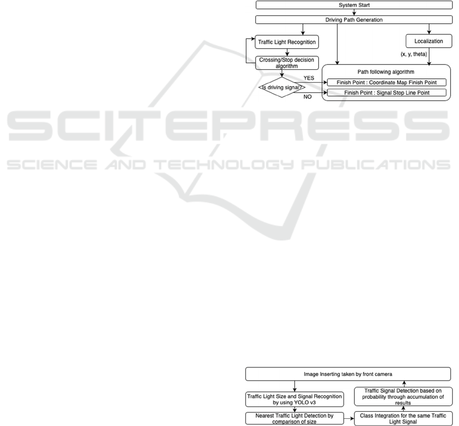
Figure 1: System block diagram summary.
In this paper, we used Hyundai Ioniq plug-in
hybrid vehicle for implementing Autonomous
Driving System based on vehicle. And the system is
consisted of the TLR, the Vehicle Localization, the
Driving Path Generation, the Path Following and the
Decision of vehicle driving signal. (Figure. 1)
2 TRAFFIC LIGHT
RECOGNITION ALGORITHM
In this paper, the TLR Algorithm is shown in Figure
2. It extracts the signal information from the front
camera, extracts signal information using CNN
model, detects proximity signal through size
comparison, class integration for the same signal, and
finally recognizes the final signal by extracting signal
information based on the cumulative probability
(Jang and Cho, 2017).
Figure 2: Traffic Light Recognition system block diagram.
Implementation of Autonomous Driving Vehicle at an Intersection with Traffic Light Recognition and Vehicle Controls
543
2.1 Camera Calibration for TLR
The camera sensor is attached near the windshield at
the front of the vehicle. The camera external
parameter calibration is experimentally performed so
that the traffic light area from the intersection entry
area to the intersection passage area is included in the
field of view of the camera. Also, As consider
intersection entry speed of vehicle, traffic light
detection should be performed before 85m from the
intersection area. Therefore, 25.36° narrow angle lens
is used to detect long-range traffic light to improve
image resolution. And to shoot traffic lights in a
variety of outdoor lighting conditions, The Camera is
configured with a 1/1.8" sensor format and a
3.45x3.45um pixel size.
2.2 Classification Model
The recognition of the traffic lights in the autonomous
driving vehicle system requires robust performance in
the weather and lighting changing environment.
Especially, in the backlight situation, the traffic light
vanishing phenomenon is happened by sunlight.
In this environment, the algorithms need very high
recognition performance and reliability in the weather
and lighting changing environment.
In this study, we implemented a Deep Learning
algorithm using a large amount of training data
including general environment image data and poor
environment image data. Also, the autonomous
driving vehicle systems require real-time processing
algorithms. The recently introduced YOLO
V3(Joseph Redmon, Ali Farhadi, 2018) guarantees
robust recognition and real-time in situations with
complex backgrounds and external lighting changes.
Therefore, we adopted it as a detecting model.
2.3 Training Data Configuration
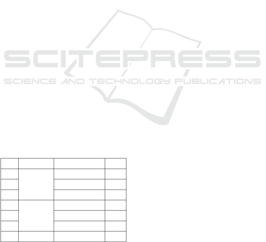
Table 1: YOLO V3 Ground Truth Data Information.
Type Block Type Signal Type Total
0
3 Signal block
Red 370
1 Yellow 242
2 Green 1119
3
4 Signal block
Red 4029
4 Yellow 96
5 Green 1914
6 4 Signal block Left Arrow / Green 1101
The images of traffic light used in the training were
taken while driving the vehicle. The images were
taken on a clear day, cloudy day and rainy weather.
The composition and number of the traffic light
images used in the experiment are shown in Table 1
(Park and Kee, 2018).
Training data classes, written Block Type and
Signal Type in Table 1, are divided into as many
classes as possible for the same traffic light signal.
And the ROI(region of interest) of the GT is
constructed by multiplying 1.2 times to width of
traffic light and multiplying 1.5 times to height of
traffic light.
2.4 Training Data Extending
The basic principle of Deep Learning is to train the
weights of neural networks according to training data
and to derive desired results. Therefore, training using
Deep Learning requires training data of various
environments. If the environment of the training data
is limited, the result will be reliable only in the trained
environment.
YOLO V3, a Learning based algorithm, was
implemented using the dedicated frame tool, Darknet
(Website-Joseph Redmon, 2018). The frame tools
provides a Data Augmentation (Salamon and Bello,
2016) methods that reinforces the kind of YOLO V3
input data. Data Augmentation methods modifies the
hue, saturation and exposure of the input training
image to create a new training image.
In this study, The Data Augmentation methods
was optimized for TLR. One of the features of the
TLR is that the position information of the signal can
be used when determining the signal type. Therefore,
in this study, we did not use only the flip option,
which is a symmetric technique, among all Data
Augmentation technologies that Darknet supports by
default.
2.5 Traffic Light Signal Detection and
Post Processing
The YOLO V3 algorithm applied to the TLR outputs
the size, position and signal type information of the
traffic lights. Generally, A large number of Traffic
Lights with different sizes are detected in one image.
Among the many Traffic Lights, what we need to
detect is the nearest one. Therefore, by comparing the
sizes, we decided what we have to recognition.
Refer to Table 1 and Figure 3. The Traffic Light
Signal Information consists of 7 type. And, It is
divided into block and signal type. The block means
the number of signal ball. And the signal means color
VEHITS 2019 - 5th International Conference on Vehicle Technology and Intelligent Transport Systems
544
of ball. In this study, we have integrated the multiple
same signals into represent one. For example, red
signal of 3 signal block and red signal of 4 signal
block is same.
Finally, to improve recognition rate, we
accumulate recognized result. And as a final detection
signal, we select the most frequent one among the
accumulated data. If we accumulate a lot of many
data, the TLR performance will be improved.
However, It requires a large amount of system load.
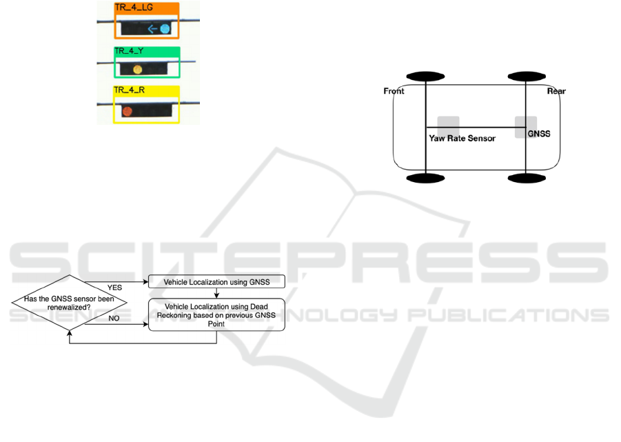
Figure 3: The result of TLR. The method of naming is TR_
[ B ]_[ C ]. TR mean Traffic Light Recognition. [ B ] mean
the number of circle in Traffic Light. And [ C ] mean sign
al of traffic light. (R : Red, LG : Left arrow and Green, Y :
Yellow).
3 VEHICLE LOCALIZATION
Figure 4: Vehicle Localization System Block Diagram.
In this paper, the vehicle localization is consisted as
shown in Figure 4. This system simply implemented
by using RTK GNSS (Website-WIKIPEDIA, 2019)
and Dead Reckoning.
The GNSS sensor is attached to the vehicle and
receives information of (x, y, theta). However, since
it has a maximum error of 10m, RTK method that has
a maximum error 10cm is used. The error is a range
that can be used for vehicle localization. However,
since the reception frequency is 1 to 5 Hz, real-time
performance in the vehicle cannot be guaranteed.
Therefore, the localization of the vehicle between the
GNSS reception intervals is estimated using Dead
Reckoning. Although the accuracy of the Dead
Reckoning is lower than that of the RTK GNSS, it is
implemented using a wheel encoder and a gyroscope
that are guaranteed real-time. (Woo et al., 2009),
(Langley, 1998)
3.1 Vehicle Localization using RTK
GNSS
We use C94-M8P module to implement RTK GNSS.
And RTK GNSS is implemented using NTRIP.
Receive the GNSS correction signal of Korean
Geographical Information Service through internet
communication and calculate the exact position of
GNSS sensor. The GNSS sensor is attached to the
upper roof of the rear axle of the vehicle like Figure
5. The reception frequency setting and the NTRIP
setting of the GNSS sensor were performed using U-
CENTER software. In this study, we set the receive
frequency to 5Hz.
Figure 5: Attaching sensor for vehicle localization.
3.2 Vehicle Localization using Dead
Reckoning
Dead Reckoning is implemented using the angular
velocity and driving speed of vehicle output from the
embedded control module equipped for autonomous
vehicle. Implementation of the vehicle localization
via Dead Reckoning follows the equations (1), (2) and
(3).
θ ≈ Δθ × Δt (1)
x
new
= x
old
× Δc × cos(θ) (2)
y
new
= y
old
× Δc × sin(θ) (3)
At equation (1), (2) and (3), θ means heading of
vehicle. It is calculated using Yaw Rate Sensor value
indicated in Figure 5. And Δc means the distance
traveled of vehicle for a short time. (x
old
, y
old
) is the
previous position of vehicle and (x
new
, y
new
) is the
current position.
4 DRIVING PATH GENERATION
USING COORDINATE MAP
The Driving Path is generated through a pre-made
coordinate map. The coordinate map is composed of
Implementation of Autonomous Driving Vehicle at an Intersection with Traffic Light Recognition and Vehicle Controls
545
points from the beginning to the end of the vehicle to
follow. Each point stores 7 kinds of information for
vehicle control
1) Address of points
2) Longitude
3) Latitude
4) Longitudinal Target Speed of vehicle
5) Stop Point Latitude
6) Stop Point Longitude
7) Stop Point Address
The points shown in Figure 5 are created based on the
GNSS sensor attachment point and uses the RTK
GNSS. At this time, RTK GPS reception frequency is
1Hz and the interval between points is about 2.78m.
5 VEHICLE CONTROL SYSTEM
AND PATH FOLLOWING
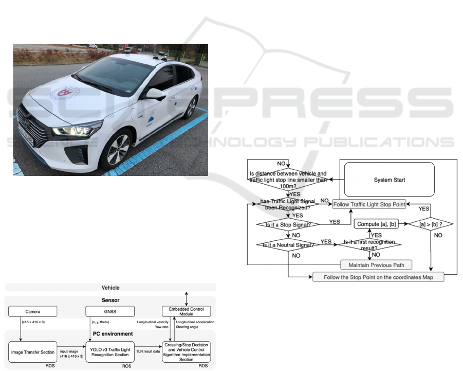
Figure 6: Hyundai Ioniq plug-in Hybrid used in the
experiment.
This paper implemented the system based on real
vehicle. The vehicle equipped with an embedded
control module and front camera used in the
experiment is shown in Figure 6. The vehicle control
system is shown in Figure 7.
Figure 7: Vehicle Control System block diagram.
The embedded control module inputs the
longitudinal acceleration and lateral steering angle of
the vehicle. In this paper, the longitudinal control of
the vehicle is implemented using the PD controller.
(Bae, 2013) And the lateral control of the vehicle is
performed using the Pure Pursuit controller. (Park
and Kim, 2015)
In this paper, the longitudinal PD controller
experimentally set the controller Gain to allow
smooth speed rise and stop. In addition, the I
component of the PID controller is not used because
the steady-state error is not significant. As the lateral
controller, Pure pursuit applied Look Ahead Point
method similar to real driver was used. The
calculation formula to get steering angle of vehicle
using Pure Pursuit is shown at (4).
δ
= tan
−1
(k × (2
(α )) / ( + 5))
(4)
At equation (4), δ means steering angle of vehicle. k
means hyper-parameter. W
b
means wheel-base length
of vehicle. α means an angle between a heading of
vehicle and a Look Ahead Point. means
longitudinal speed of vehicle.
6 STOP/CROSSING DECISION
ALGORITHM
The Stop/Crossing Decision Algorithm is an
algorithm that judges the driving and stopping
behaviour of the vehicle. And the system is
summarized in Figure 8 as block diagram.
Figure 8: Decision algorithm block diagram. [a] is a result
of adding (5) and (6). [b] is a result of (7).
The Stop/Crossing Decision Algorithm is
implemented based on the recognized signal, the
speed of the vehicle, the distance between the vehicle
and the stop line and the distance of the intersection
section. The recognized signal is finally output in
three states of Driving, Neutral and Stop. And each
means that the result of the TLR is green, yellow and
red.
VEHITS 2019 - 5th International Conference on Vehicle Technology and Intelligent Transport Systems
546
For the Neutral signals, the signal is determined
by the speed of the vehicle and the distance between
the stop line and the vehicle. If the sum of the
traveling time (5) to the intersection passing time (6)
is shorter than the holding time of neutral signal (7),
this algorithm determines it as a Driving signal. If not,
However, this algorithm determines it as a Stop signal.
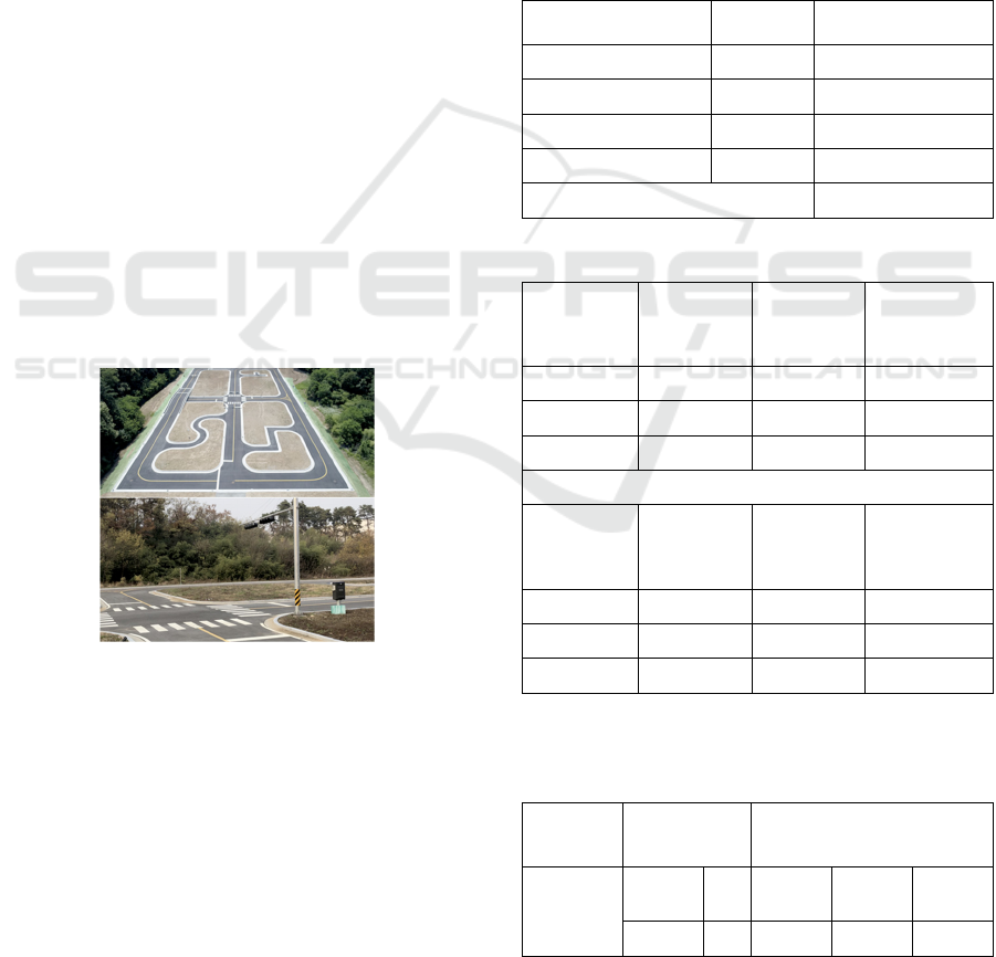
In this paper, We implement this system at
Autonomous Vehicle Proving Ground equipped with
intersection located in Ochang campus, Chungbuk
National University.(Figure 9) As constant variable,
Therefore, we determines d
Intersection
as 7m,v
Intersection
as
10kph and t
NeutralTime
as 5 sec.
t
StopLine
= (d
StopLine
/v
SignalDetection
)×3/2 (5)
t
Intersection
= (d
Intersection
/v
Intersection
)
(6)
For the Driving signal, the vehicle follows the stop
line of the traffic light. At this time, the longitudinal
target velocity is linearly reduced to zero.
7 EXPERIMENTAL METHODS
AND RESULT
This experiment is progressed in Autonomous
Vehicle Proving Ground with the intersection
equipped with traffic light located in Ochang campus,
Chungbuk National University.(Figure 9)
Figure 9: Autonomous Vehicle Proving Ground with Inters
ection equipped with Traffic Light.
This system was implemented with maximum
40kph in the straight section and maximum 10kph in
the corner section. The performance of this system is
shown in Table 2, 3, 4, 5 and Figure 10.
Table 2 shows the performance evaluation of the
TLR algorithm. It defines a sequence as a distance of
85 m from a traffic light to a point passing through an
intersection.
Table 3 and 4 shows the vehicle control
performance for lane departure and stopping at stop
point under real driving environment.
Table 5 shows the decision performance
according to the Stop or Crossing in the yellow state.
Figure 10 is a longitudinal and lateral control
performance graph. And This data was written as one
second intervals. At this Figure, Lateral Distance
Error means vertical distance error between the path
heading and the vehicle.
Table 2: The result of the TLR. The confusion matrix is
used for the performance evaluation, and it is defined as one
sequence from the distance of 85m to the moment when the
vehicle passes through the traffic lights (Park and Kee,
2018).
Type Sequence Result
Red / Yellow 30 30TP
Green 30 30TP
Green to Yellow 15 15TP
Red to Green 15 15TP
Recall, Precision 100%
Table 3: Vehicle Lateral Control Performance Result.
90° Corner
section
(kph)
Attempts
Success
(In Lane)
Failure
(Out Lane)
10 25 25 0
15 25 23 2
20 25 19 6
Straight
section
(kph)
Attempts
Success
(In Lane)
Failure
(Out Lane)
20 25 25 0
30 25 25 0
40 25 25 0
Table 4: Vehicle Longitudinal Control Performance Result.
It indicates the distance error between the stop line and the
vehicle when the vehicle is stopped.
Attempts Result
Stop Point Distance Error
(m)
25
Over
line
2 0.012 0.021 0.017
In line 23 0.011 0.108 0.032
Implementation of Autonomous Driving Vehicle at an Intersection with Traffic Light Recognition and Vehicle Controls
547
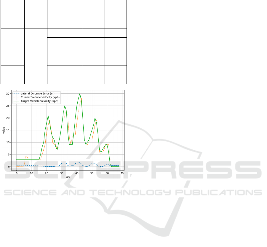
Table 5: The result of intersection driving of autonomous
vehicle at Neutral Signal Decision State.
Straight
Course
(kph)
90°
Curved
Course
(kph)
Neutral Signal
Decision
Result
Success Failure
20
10
Stop 15 0
Crossing 15 0
30
Stop 15 0
Crossing 15 0
40
Stop 15 0
Crossing 15 0
Figure 10: The result of vehicle’s lateral, longitudinal
control according to vehicle’s velocity. Curved sections
mean 90° corner course.
8 CONCLUSIONS
In this paper, the autonomous driving vehicle system
was implemented using real vehicle equipped with
intelligent sensor and embedded control module at
intersection area equipped with traffic light. The
study was conducted on three areas: Traffic Light
Recognition, judgment of behavior of vehicle based
on recognized signals and vehicle control.
The system was successfully implemented at
Autonomous Vehicle Proving Ground located in
Ochang campus, Chungbuk National University.
At traffic light recognition and signal judgment,
the behavior of vehicle recognized as yellow signal
was mainly studied. And this content was written at
‘6. STOP/CROSSING JUDGMENT ALGORITHM’.
In this study, the holding time of the yellow signal
from traffic light was fixed as 5 sec. To implement
robust judgment algorithm, However, the systems
have to receive accurate holding time. For example,
if we use V2X methods, we can get the accurate
holding time to maintaining yellow signal.
At vehicle control, we implemented this system
using localization of vehicle and longitudinal/lateral
control. At part of localization, by using both RTK
GNSS and Dead Reckoning, ‘3. VEHICLE
LOCALIZATION’ was consisted. However, in this
study, lateral control was not stable due to GNSS
heading error which randomly changed maximally up
to 5
°
. Therefore, it is necessary to compensate the
problems by a technique such as a Kalman filter. Also,
it is difficult to getting trusting data from GNSS
located between high-rise buildings. Also, In case of
Dead Reckoning, Because it has low reliability
compared to GNSS, it is used as complementary
algorithm of GNSS. However, if it is implemented
through a high-quality algorithm, the performance of
the localization will improve.
At control of vehicle, PD controller is used to
longitudinal control. And Pure Pursuit controller is
used to lateral control. More details are covered in ‘5.
VEHICLE CONTROL SYSTEM AND PATH
FOLLOW’. In this study, the PD controller of
longitudinal control is implemented in the low speed
situation. Therefore, the stopping and running
performance cannot be relied on in high speed
situation. Actually, in real road, there are many
challenging environments, such as inclement weather,
high curvature road, and so on. And to comfortable
ride, accurate control is necessary. Also, the Pure
Pursuit controller applied to lateral control is not
stable for all environment. If you want, advanced
control algorithm, such as Kinematic control, LQR
with FF control, Preview control, MPC (Lee and Yi,
2015), and so on, is needed.
As a result of this study, the conclusions could be
summarized that it is experimentally proved that it is
possible to partially implement an autonomous
driving system using a commercial vehicle through
public recognition algorithm and control algorithm
with proposed stop/crossing decision algorithm.
ACKNOWLEDGEMENTS
This work was supported by Institute for Information
& communications Technology Planning and
Evaluation (IITP) grant funded by the Korea
government (MSIT) (No. R7117-16-0164,
Development of wide area driving environment
awareness and cooperative driving technology which
are based on V2X wireless communication).
VEHITS 2019 - 5th International Conference on Vehicle Technology and Intelligent Transport Systems
548

REFERENCES
Road Traffic Authority, Traffic Accident Detailed
Statistics, http://bitly.kr/d54R, Korea, 2018.
G. Reina, D. Johnson, J. Underwood, 2015, Radar Sensing
for Intelligent Vehicles in Urban Environments, MDPI
Sensors Journal, Vol.15, No.6 pp.14661- 14678.
D. J. Lim, 2014, Obstacle tracking and Vehicle Recognition
Based on Lidar and Vision Sensor Fusion, M.S, Ajou
University, Suwon.
Pyeong-Geun Jo, Joon-Woong Lee, 2015, Traffic Light
Detection Using Morphometric Characteristics and
Location Information in Consecutive Images, Journal
of Institute of Control, Robotics and Systems, Vol.21,
No.12, pp.1122-1129.
Taekhoon Jung, Jungha Kim, 2017, Traffic Light
Recognition based on HSV/YCbCr Color Model and
Morphological Feature, KSAE Annual Conference
Proceedings, pp.547-551.
Website-WIKIPEDIA, 2019, CNN, http://bitly.kr/ieEJd.
Sungwoo Heo, Taehyung Park, 2016, Localization of
Autonomous Vehicle Using 3D LIDAR and IMU,
KSAE Annual Conference Proceedings, pp.850-850.
Su Young Kim, Jung-Min Lee, Dong Hwal Lee, Man
Hyung Lee, 2007, Unmanned Navigation of Vehicle
Using the Ultrasonic Satellite System, Journal of
Institute of Control Robotics and Systems, Vol.13, No.9,
pp.875-882.
Hojung Jung, Donghwi Lee, Seungki Kim, Changsup Kim,
Kunsoo Huh, 2012, Development of Vehicle Position
Estimator using Dead Reckoning Algorithm, KSAE
Annual Conference Proceedings, pp.1255-1257.
Jarrod M. Snider, 2009, Automatic Steering Methods for
Autonomous Automobile Path Tracking, Robotics
Institute Carnegie Mellon University Pittsburgh, CMU-
RI-TR-09-08.
Chulhoon Jang, Sungjin Cho, Sangwoo Jeong, Jae Kyu
Suhr, Ho Gi Jung, 2017, Traffic light recognition
exploiting map and localization at every stage, Expert
Systems With Applications, Vol.88, pp.290-304.
Joseph Redmon, Ali Farhadi, 2018, YOLOv3: An
Incremental Improvement, CVPR.
Changhyeon Park, Seok-Cheol Kee, 2018, A Study on the
Traffic Light Recognition Based On Deep Learning for
Urban Autonomous Driving, KSAE Spring Conference
Proceeding, pp.811-812.
Website-Joseph Redmon, 2018, YOLO v3 darknet frame,
https://pjreddie.com.
Justin Salamon, Juan Pablo Bello, 2016, Deep
Convolutional Neural Networks and Data
Augmentation for Environmental Sound Classification,
IEEE Signal Processing Letters, Vol.23, No.3, pp.279-
283.
Website-WIKIPEDIA, 2019, RTK GPS, https://en.wiki
pedia.org/wiki/Real-time_kinematic.
HoonJe Woo, SeungKwon Jung, BongGeun Cho, JungHa
Kim, 2009, Research of navigation algorithm for
Unmanned Gound Vehicle based on Real Time
Kinematic(RTK)-GPS, KSAE Spring Conference
Proceedings, pp.972-976.
Richard B. Langley, 1998, RTK GPS, GPS WORLD
September 1998 INNOVATION, pp.70-76.
Jong-Il Bae, 2013, An Adaptive Cruise Control Systems for
Inteligent Vehicles in Accordance with Vehicles
Distance, The transactions of The Korean Institute of
Electrical Engineers, Vol. 62, No. 8, pp.1157-1162.
Junbum Park, Jungha Kim, 2015, Development of Pure
Pursuit Algorithm using Fuzzy Theory-based Look-
Ahead Distance Function, Kukmin University, Master
degree paper.
Jun-Yung Lee, Kyong-Su Yi, 2015, MPC based Steering
Control using a Probabilistic Prediction of Surrounding
Vehicles for Automated Driving, Journal of Institute of
Control, Robotics and Systems, Vol.21, No.3, pp.199-
209.
Implementation of Autonomous Driving Vehicle at an Intersection with Traffic Light Recognition and Vehicle Controls
549
