
An Approach to Determine & Apply Solutions to Solve Detected
Problems in Restructured Deployment Models using First-order Logic
Karoline Saatkamp, Uwe Breitenb
¨
ucher, Michael Falkenthal, Lukas Harzenetter and Frank Leymann
Institute of Architecture of Application Systems, University of Stuttgart, Universit
¨
atsstrasse 38, 70569 Stuttgart, Germany
Keywords:
Deployment Model, Pattern, Logic Programming, Pattern-based Solution, Model Adaptation, TOSCA.
Abstract:
New paradigms such as edge computing opened up new opportunities for distributing applications to meet use-
case-specific requirements. For automating the deployment of applications, deployment models can be created
that describe the application structure with its components and their relations. However, the distribution is
often not known in advance and, thus, deployment models have to be restructured. This can result in problems
that have not existed before, e.g., components previously deployed in the same network were distributed,
but security mechanisms are missing. Architecture patterns can be used to detect such problems, however,
patterns describe only generic technology-independent solutions, which cannot automatically be applied to
applications. Several concrete technologies exist that implements the pattern. Which solutions are applicable
to a particular application is determined by, e.g., its hosting environment or used communication protocol.
However, the manual effort to determine and implement appropriate solutions is immense. In this work, we
present an approach to automate (i) the determination of solutions for an application using first-order logic
and (ii) the adaptation of its deployment model accordingly. To validate the practical feasibility, we present a
prototype using the cloud standard TOSCA and the logic programming language PROLOG.
1 INTRODUCTION
The rising number of cloud services and new
paradigms such as edge or fog computing (Mahmud
et al., 2018) opened up new opportunities. Cost-
savings through pay-per-use models can be achieved
and, e.g., new Industry 4.0 use cases realized through
deployments closer to the data sources. Thus, ap-
plication components are distributed to meet use
case-specific requirements: data-intensive, non-time-
critical components are placed in a private or public
cloud and time-critical components are moved to the
edge. However, the distribution is often not known in
advance: (i) the operation differs from the develop-
ment environment, (ii) each user has different prefer-
ences, (iii) and requirements change over time which
leads to necessary restructuring and adaptations of an
application and, thus, increases the management ef-
fort (Breitenb
¨
ucher et al., 2013; Eilam et al., 2006).
For automating the deployment and management
of applications several deployment systems have been
developed. In addition to provider-specific technolo-
gies, such as AWS Cloud Formation
1
, and provider-
1
https://aws.amazon.com/cloudformation/
independent technologies, such as Kubernetes
2
, stan-
dards such as the Topology and Orchestration Spec-
ification for Cloud Applications (TOSCA) (OASIS,
2013; OASIS, 2018) were developed to ensure porta-
bility and interoperability. Based on these approach-
es, declarative deployment models can be created.
Such models describe an desired application’s struc-
ture with its components and their relations (Endres
et al., 2017). Depending on use-case-specific require-
ments and environmental conditions, an application’s
structure can be adapted to reflect the distribution of
the application (Saatkamp et al., 2017; Carrasco et al.,
2015; Ardagna et al., 2012; Eilam et al., 2006). How-
ever, the distribution can result in incompatibilities,
communication restrictions, or security issues. For
example, components that must be accessed are de-
ployed in environments that restrict inbound commu-
nication, or security mechanisms are required because
components that previously communicated over a pri-
vate network now communicate over the Internet.
Proven solutions and best practices for such re-
curring problems are captured in different IT do-
mains in form of patterns. Patterns are textual
2
https://kubernetes.io/
Saatkamp, K., Breitenbücher, U., Falkenthal, M., Harzenetter, L. and Leymann, F.
An Approach to Determine Apply Solutions to Solve Detected Problems in Restructured Deployment Models using First-order Logic.
DOI: 10.5220/0007763204950506
In Proceedings of the 9th International Conference on Cloud Computing and Services Science (CLOSER 2019), pages 495-506
ISBN: 978-989-758-365-0
Copyright
c
2019 by SCITEPRESS – Science and Technology Publications, Lda. All rights reserved
495
descriptions that support the design process of com-
plex systems (Fehling et al., 2014; Schumacher
et al., 2006; Hohpe and Woolf, 2004). This knowl-
edge can be used to detect problems in deployment
models that can be solved by known solution con-
cepts (Saatkamp et al., 2019). For example, to en-
sure a secure exchange of sensitive data, the SECURE
CHANNEL (Schumacher et al., 2006) is a known pat-
tern that can be applied to solve this problem.
Patterns, however, only describe a conceptual so-
lution, which is technology-independent. Thus, the
technologies that can be used for a particular appli-
cation must be identified and implemented manually.
For example, for realizing the SECURE CHANNEL
pattern several solutions exist: If application compo-
nents communicate over HTTP, TLS can be used to
secure their data exchange. In case both components
are hosted on virtual machines (VMs), a virtual pri-
vate network (VPN) can be established using IPsec.
Both solutions result in an encrypted communication,
but which one can be applied depends on the deploy-
ment model and technical conditions. For identify-
ing suitable solutions, several technical aspects must
be considered: the software artifacts, the hosting en-
vironments, the used communication protocols, and
many more. Thus, the manual effort to implement a
solution and to adapt a deployment model is immense.
In this paper, we tackle these challenges by an
approach, which takes the technical aspects into ac-
count when selecting and applying suitable solutions
in an automated manner. The technical aspects are
essential: They determine (i) the suitable solutions
and (ii) the necessary adaptations in the deployment
model. As first-order logic is usually used for declar-
ative knowledge representation and reasoning about
a knowledge base, we use it to express the knowl-
edge about the deployment model and for reasoning
to identify suitable solutions. The required adapta-
tion steps depend on the identified technical condi-
tions and the solution that shall be implemented. The
specific adaptation logic is therefore encapsulated in
algorithms that adapt the deployment model accord-
ing to the selected solution. To validate the practical
feasibility of our approach, we present a prototype
based on the cloud standard TOSCA and the logic
programming language PROLOG to identify and ap-
ply solutions to adapt TOSCA deployment models.
The remainder of this paper is structured as fol-
lows: Section 2 introduces fundamentals and Sec-
tion 3 motivates our concept. Section 4 gives an
overview and Section 5 presents the formalization and
application scenarios of our approach. The prototype
is presented in Section 6. Section 7 discusses related
work and Section 8 concludes the paper.
OpenStack
(OpenStack-
Liberty-12)
App-OS
(Ubuntu-VM)
Apache Web
Server
(Apache-2.4)
Tomcat
(Tomcat)
Java-App
(WAR)
PHP-WebApp
(PHP-7-App)
Public
Label
ComponentName
(ComponentType)
Private
hostedOn
HTTPconnectsTo
username: admin
password: *****
location: dev
sensitiveData: true
HTTP
(HTTPconnectsTo)
RelationName
(RelationType)
Figure 1: Exemplary topology-based deployment model
[adapted from (Saatkamp et al., 2019)].
2 FUNDAMENTALS
The concept of patterns that capture architecture
knowledge and solutions that implement those pat-
terns are the basis for solving detected problems in
restructured declarative deployment models. Such a
deployment model contains the application structure
as a directed graph and is called topology-based de-
ployment model (Endres et al., 2017). Therefore, we
first introduce basics about topology-based deploy-
ment models, then we explain the concept of patterns
and their implementations for concrete applications.
2.1 Topology-based Deployment Model
A topology-based deployment model, topology for
short, is a graph-based model and describes the struc-
ture of an application that shall be deployed. This typ-
ically comprises the application’s components, their
relations, and configuration properties. In contrast
to imperative deployment models, declarative deploy-
ment models describe the desired structure of the ap-
plication and not the specific deployment steps. The
deployment logic of the individual application com-
ponents is inferred by a runtime from the declared ap-
plication structure (Breitenb
¨
ucher et al., 2014a).
In Figure 1 an exemplary topology is depicted.
The application consists of two components, PHP-
WebApp and Java-App that exchange sensitive data
over HTTP. Additional information about the data
CLOSER 2019 - 9th International Conference on Cloud Computing and Services Science
496

TLS for
HTTP
SECURE
CHANNEL
Problem: How do we ensure that data being
passed across public space is secure in transit?
Context: […] The application must exchange
data with the client. A percentage of this
data will be sensitive in nature.
Solution: Create secure channels for sensitive
data […] Exchange information between
client and server to allow them to set up
encrypted communication […]
IPsec VPN
…
Figure 2: SECURE CHANNEL pattern and possible solutions
for solving the problem.
characteristics is attached to the HTTP relation as
property. The PHP-WebApp is provided by an
Apache web server hosted on an Ubuntu-VM. The
Java-App is running on a Tomcat application server
deployed on the same VM hosted on an OpenStack.
The location property of the OpenStack component
indicates that it is running in the development envi-
ronment. For instantiating a VM on the OpenStack,
inputs such as the username or password are required.
Each component and relation has a specific type.
These reusable component types, e.g. Ubuntu VM,
and relation types, e.g. the specific HTTPconnectsTo,
define the semantics of the topology elements. The
connectsTo relation expresses that the source compo-
nent establishes a connection to the target component
and thus the source component requires the communi-
cation endpoint. The hostedOn relation indicates the
component that serves as host for another one.
In addition, the distribution decisions can be re-
flected in the deployment model to automate the dis-
tribution. These distribution targets are modeled, for
example, as labels attached to the application-specific
components, which represent the business logic. In
the example in Figure 1, the application-specific com-
ponents, PHP-WebApp and Java-App, shall be dis-
tributed: the PHP-WebApp shall be deployed in a
public cloud and the Java-App in a private cloud.
Based on these target labels, infrastructure compo-
nents in the specified target environment that are able
to host the components are selected and the model
is adapted accordingly by inserting the new hosting
components. For example, an AWS EC2 is inserted
to host the PHP-WebApp and an OpenStack for the
Java-App (Saatkamp et al., 2017).
The cloud standard TOSCA is one possibil-
ity to model such declarative deployment mod-
els (Bergmayr et al., 2018). It provides a vendor- and
technology-independent meta model and is, therefore,
selected for the prototypical implementation of our
approach, which is described in detail in Section 6.
2.2 Patterns & Concrete Solutions for
Solving Problems
Patterns are a well-established concept to gather
knowledge and best practices to solve recurring prob-
lems in different domains. Originally introduced by
Alexander et al. (1977) for the architecture of build-
ings and towns, the concept was transferred to various
IT domains. Several communities collected architec-
ture and design knowledge in form of patterns. For
example, patterns for application integration (Hohpe
and Woolf, 2004), security architectures (Schumacher
et al., 2006), and cloud computing (Fehling et al.,
2014) were published. Patterns are textual descrip-
tions, whereby defined pattern formats ease the struc-
turing. Although the formats differ slightly, the es-
sential parts are always the same: the description of
(i) a recurring problem that appears (ii) in a con-
text along with a (iii) conceptual solution allowing
to overcome the problem. The conceptual solution
is described in a generic and technology-independent
manner (Alexander et al., 1977). Each pattern has a
name that indicates the thing it represents.
In Figure 2 an excerpt of the SECURE CHANNEL
pattern description is shown. This pattern serves as
running example for demonstrating our concepts in
this paper. This pattern addresses the problem of se-
curing the exchange of sensitive data that are passed
over a public network. The pattern states that a se-
cure channel for an encrypted communication shall
be created. In the Implementation and Known Uses
sections of the pattern commonly used technologies
are described in more or less detail. For example, the
TLS encryption for HTTP is described in detail. In
addition, IPsec and other VPN technologies are men-
tioned as possible implementations. However, the
listed examples have no claim to completeness and
are, of course, still written text, which cannot be used
directly to solve a problem in a certain application.
Therefore, the applicable technologies have to be de-
termined manually and the effort to implement the so-
lution have to be spent each time the pattern is applied
to solve a problem at hand.
To enable the documentation of such concrete
implementations of a pattern in a reusable manner,
Falkenthal et. al. (2014a; 2014b) introduced a con-
cept to describe them as solution implementations
linked to a pattern. These solution implementations
are reusable artifacts, for example, executable soft-
ware artifacts, code snippets, or configuration files.
Selection criteria determine when to use a certain so-
lution implementation. This concept eases the pattern
application to similar use cases.
An Approach to Determine Apply Solutions to Solve Detected Problems in Restructured Deployment Models using First-order Logic
497
insecureCommunication(C1, C2) :-
relation(C1, C2, R),
relationOfType(R, connectsto),
property(R, sensitiveData, true),
differentLocations(C1, C2),
not(property(R, security, true)).
Topology-based Deployment ModelFormalized Problem & Context
Problem:
Insecure communication
PHP-WebApp
Java-App
How to solve
the detected
problem?
(VM) (VM)
(IaaS)
location: ex location: in
(Open-
Stack)
sensitiveData:
true
Java-
App
PHP-
WebApp
HTTP
(1)
formalize
Problem: How do we ensure
that data being passed across
public space is secure in transit?
Context: […] The application must exchange
data with the client. A percentage of this
data will be sensitive in nature.
Solution: Create secure channels for
sensitive data […] Exchange information
between client and server to allow them to
set up encrypted communication […]
SECURE
CHANNEL
Architecture Patterns
insecure communication
(3)
problem
detected
(2)
detect
problems
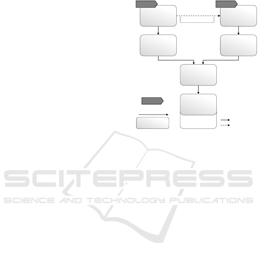
Figure 3: Pattern-based problem detection in restructured topologies (Saatkamp et al., 2019).
3 MOTIVATING SCENARIO
Applications often need to be distributed across mul-
tiple environments to meet use-case-specific require-
ments. However, the distribution is often not known
in advance: When developing complex applications,
the operation environment often differs from the de-
velopment environment. In addition, each user for
whom the application is deployed has different re-
quirements. As a result, problems can arise that have
not existed before: For example, components that
must be accessed are placed in environments that pre-
vent inbound communication. Besides, security is-
sues can occur, e.g., components that were previously
intended to be deployed on the same VM shall now be
provisioned on separate VMs that communicate using
a public network, i.e. the Internet. The distribution
of the components must also be reflected in the cor-
responding topology. The topology depicted in Fig-
ure 3 is a simplified representation of a restructuring
of the topology in Figure 1: The PHP-WebApp shall
be deployed on a public cloud and the Java-App on
a private cloud. Previously, both components were
intended for the deployment at the same VM. As a re-
sult, the two components exchange sensitive data over
a public network instead of internally on the same ma-
chine. This problem only arose through the distribu-
tion of the components. In order to ensure that the
intended behavior of an application is preserved after
restructuring, such problems have to be detected.
Best practices for solving recurring problems
exist in form of patterns. Since patterns pro-
vide only textual descriptions, we presented an ap-
proach for automated problem detection in restruc-
tured topology-based deployment models in previous
works (Saatkamp et al., 2019; Saatkamp et al., 2018).
The problem detection is based on formalized prob-
lem and context descriptions of patterns. Figure 3 out-
lines the problem detection approach: On the left, an
excerpt of the SECURE CHANNEL pattern is shown.
First, the problem and context description are formal-
ized. The problem insecure communication between
two components exists if they are connected with a
connectsTo relation with the property sensitiveData =
true, the two components are hosted in different envi-
ronments, and no security properties are contained.
Based on this formalization, in the second step it can
be automatically detected whether the problem exists
in a topology. In Figure 3 the problem is detected
in the topology: Between the two components, PHP-
WebApp and Java-App, a connection shall be estab-
lished to exchange sensitive data. Each component is
hosted on a separate environment and, thus, the com-
munication takes place over a public network. In ad-
dition, no security mechanisms are used. Thus, the
SECURE CHANNEL pattern shall be applied.
However, the conceptual solution described by a
pattern is not sufficient to be directly applied to an ap-
plication as it describes the solution generically and
technology-independently. The solution of the SE-
CURE CHANNEL pattern states to set up an encrypted
communication. To solve the insecure communica-
tion problem in Figure 3, for example, TLS proxy
components can be inserted to secure the communi-
cation between PHP-WebApp and Java-App or to es-
tablish a VPN between both machines, the VMs can
be exchanged by IPsec-configured VMs. Although
the Implementation and Known Uses sections of the
pattern mention a number of technologies, the deter-
mination of an appropriate encryption technology for
a particular application and the adaptation of the re-
spective topology have to be done manually. More-
over, the technical requirements of the technologies
must be known and considered for selecting an ap-
propriate one. This is time-consuming and requires
immense technical know-how. For this, we present an
approach to automate (i) the determination of appro-
priate solutions and (ii) the adaptation of the topology.
CLOSER 2019 - 9th International Conference on Cloud Computing and Services Science
498
TA
2
TLS for
HTTP
Topology-based Deployment Model
DC
í
Deployment Context
TA
i
Topology Adaptation AlgorithmLegend:
(VM)
Java-
App
PHP-
WebApp
(VM)
(IaaS)
location: ex location: in
(Open-
Stack)
F-Proxy B-Proxy
HTTP HTTPS HTTP
Architecture Patterns
TA
1
(VM) (VM)
C
2
C
1
HTTP
(VM) (VM)
C
2
C
1
DC
1
DC
2
IPsec
determine applicability of TA
adapt topology
SECURE
CHANNEL
(VM) (VM)
(IaaS)
location: ex location: in
(Open-
Stack)
sensitiveData:
true
Java-
App
PHP-
WebApp
HTTP
solution realized
in topology
(1)
detect matching
deployment contexts
deployment
context
DC
2
DC
1
(2)
select preferred
solution
TLS for
HTTP
(3)
adapt
topology
TA
2
Figure 4: Solution determination, solution selection, and topology adaptation for solving problems in topologies.
4 SOLUTION DETECTION AND
TOPOLOGY ADAPTATION
Patterns can be used to detect problems in topolo-
gies as described in Section 3. This is done on the
basis of the problem and context description of pat-
terns. This generic and technology-independent de-
scription is sufficient as indicator for problems. How-
ever, the conceptual solution stated by a pattern de-
scription and its textually described exemplary imple-
mentations are not sufficient for an automated imple-
mentation of a solution and topology adaptation. To
implement a pattern several concrete solutions exist.
Which of these solution implementations is suitable
for a particular topology and how the topology have
to be adapted depends, e.g., on the used hosting en-
vironments, the middleware, or the communication
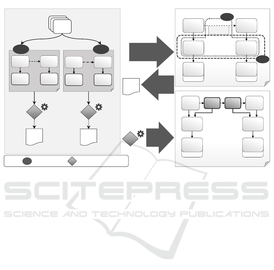
protocols in the topology. Figure 4 gives an overview
of our approach for (1) determining appropriate solu-
tions for a certain topology, (2) selecting one of these
solutions, and (3) adapting the topology for realiz-
ing the solution in an automated manner. This eases
problem solving in topologies. In the following, the
approach is described in detail. First, the concept of
matching deployment contexts for detecting appropri-
ate solution for a topology is presented, then the solu-
tion selection and topology adaptation are described.
4.1 Matching Deployment Contexts for
Determining Appropriate Solutions
In Figure 4 on the left, the SECURE CHANNEL pat-
tern with two solutions is depicted. IPsec can be used
to secure the communication at the network layer. For
this, a VPN connection between the two hosts is es-
tablished. For securing the communication at the ap-
plication layer, TLS certificates can be used, e.g., to
secure a HTTP connection. To apply these solutions
to a topology, several conditions have to be fulfilled:
IPsec can only be used if the hosts, i.e., the VMs, are
manageable in the topology. In case HTTP is used as
communication protocol, TLS proxies can be inserted
between the two communicating components. These
technical details are referred to as deployment context.
The TLS encryption mechanism is independent of
the hosting environment, but the required adaptation
steps vary depending on the hosts involved: The adap-
tation steps for inserting a TLS proxy for a component
hosted on a VM differ from the adaptations required
to attach a sidecar container to a docker container
hosted on a docker engine. Thus, for determining (i)
appropriate solutions for a certain topology and (ii)
the required adaptation to realize the solution in the
topology, the deployment context of the components
for which a problem is recognized is essential.
An Approach to Determine Apply Solutions to Solve Detected Problems in Restructured Deployment Models using First-order Logic
499

The required deployment context (DC) for the
adaptation steps to realize IPsec and the DC to real-
ize the TLS encryption for a HTTP communication
between two application components hosted on VMs
are graphically shown in Figure 4. The required adap-
tation steps that have to be executed are encapsulated
in a Topology Adaptation Algorithm (TA). TA
1
can be
applied to realize IPsec in a topology where the two
components C
1
and C
2
, for which the insecure com-
munication problem has been detected, are hosted on
VMs. This is described by DC
1
. TA
2
, on the other
hand, can be used to implement TLS for HTTP if
components C
1
and C
2
additionally use HTTP as their
communication protocol. The TLS for HTTP solu-
tion can be used independent of the hosting environ-
ment, however, the adapation of the topology differs
depending on the hosts. If the machines are not man-
ageable and, for example, docker is used as container
management system, different adaptation steps have
to be executed. Thus, the same solution can be real-
ized by several TAs, as shown in Figure 5.
In order to determine the applicable TAs and thus
the appropriate solutions, the matching DCs in the
topology have to be detected. In Figure 4, both DCs
match with the components and relations in the topol-
ogy: The PHP-WebApp and Java-App components
are hosted on components of component type VM.
This is required by DC
1
and DC
2
. In addition, the
relation between PHP-WebApp and Java-App is a
HTTP relation, which is required by DC
2
. Therefore,
TA
1
as well as TA
2
are applicable to the topology and
IPsec and TLS for HTTP are appropriate solutions.
Since the absence of elements is also important to de-
termine the DC, graph matching approaches are not
appropriate for the automated detection of matching
DCs. In Section 5 our approach to use first-order logic
for the automated DC detection is presented.
4.2 Solution Selection
The matching DCs detected in the previous step de-
termine the applicability of the linked TAs and thus
the appropriate solutions that can be realized in the
considered topology. A variety of possible solutions
can be chosen to solve a specific problem, since sev-
eral DCs can match with the elements in the topology.
The preferred solution has to be selected manually, as
user-specific preferences must be taken into account.
In the example shown in Figure 4 the TLS for HTTP
solution is selected. Based on this selection, the topol-
ogy has to be adapted accordingly.
TA
3
TLS for
HTTP
TA
2
(Docker
Engine)
(Docker
Engine)
C
2
C
1
HTTP
DC
3
(VM) (VM)
C
2
C
1
HTTP
DC
2
X
Figure 5: Different deployment contexts (DCs) for deter-
mine the applicability of different adaptation algorithms
(TAs) for the same solution (TLS for HTTP).
4.3 Topology Adaptation
A topology has to be adapted to solve a particular
problem. The adaptation is done by a topology adap-
tation algorithm (TA). The TAs encapsulate the adap-
tation steps that must be executed to realize a defined
solution. TAs can be made available through a solu-
tion repository (Fehling et al., 2015). A DC and its
linked TA are tightly coupled in terms of the consid-
ered topology elements. A TA can only operate on
the topology elements that are defined in the corre-
sponding DC. The determination of the applicability
of a TA is one of the purposes of the DC. Therefore,
the applicability is ensured under the assumption that
all new components and relations to be inserted are
available to the algorithms, e.g., in a repository.
In the previous step, the preferred solution was se-
lected. For the selected solution in Figure 4, the al-
gorithm TA
2
is attached to the matching deployment
context DC
2
. The algorithm is applied to the topology
and adapts the topology according to the linked solu-
tion: To enable the encryption of the communication
with TLS certificates, two proxies have to be injected
between the communicating components to encrypt
the requests and responses. These proxies are hosted
on the respective VM of each component. As a result,
the TLS for HTTP solution is realized and the inse-
cure communication problem is solved in the topol-
ogy through the adaptations implemented in TA
2
.
In a topology, several problems can be detected
and the adaptation of a topology can result in new pro-
blems. However, the order in which the problems are
tackled is not defined. The problems can be selected
and solved one after the other. Thus, the problem de-
tection and solution application is an iterative process.
CLOSER 2019 - 9th International Conference on Cloud Computing and Services Science
500

Topology in Graphical Notation
VM-Frontend
(VM)
VM-Backend
(VM)
AWS EC2
(IaaS)
location: ex location: in
OpenStack
(OpenStack)
sensitiveData:
true
Java-App
(WAR)
PHP-
WebApp
(PHP-7-App)
HTTP
(HTTPconnectsTo)
relation
type
relation
component
is source of
1
*
is target of
1
*
component
type
1
*
topology
element
1
is of type
topology
element
type
property
has
*
*
Topology-Based Deployment Meta Model
*
is of type
Syntax & Semantic
component(PHP-WebApp) ⋀
componentType(PHP-WebApp, PHP-7-App) ⋀
component(Java-App) ⋀
componentType(Java-App, WAR) ⋀
relation(PHP-WebApp, Java-App, HTTP) ⋀
relationType(HTTP, HTTPconnectsTo) ⋀
property(HTTP, sensitiveData, true) ⋀
…
Formalize
Topology in First-Order Logic
Figure 6: Topology elements expressed as predicates using first-order logic based on the given syntax and semantic of the
topology meta model (Saatkamp et al., 2019).
5 SOLUTION DETECTION
USING FIRST ORDER LOGIC
The objective of this paper is to automate (i) the deter-
mination of appropriate solution for a particular topol-
ogy and (ii) the adaptation of a topology according to
the selected solution. The DC determines the applica-
bility of an algorithm to realize a specific solution in a
topology. Several approaches exist that use subgraphs
detection in graph-based models to determine the ap-
plicability of patterns or solutions (Harzenetter et al.,
2018; Guth and Leymann, 2018; Breitenb
¨
ucher et al.,
2014b; Eilam et al., 2006). However, this means that
the absence of elements in a topology cannot be de-
tected and transitive dependencies cannot be mapped
natively. Thus, this approach cannot been used to de-
tect problems nor to determine appropriate solutions.
Therefore, we use first-order logic to express the DC
and to determine whether a TA and, thus, a solution
is applicable. First, the topology and its elements
have to be expressed as first-order predicates (cf. Sec-
tion 5.1), then logical formulas can be used to express
the DC (cf. Section 5.2). Based on this, it can be de-
rived whether a DC matches with the elements in a
topology. If it matches, the linked TA can be applied
to the topology. Section 5.3 discusses restrictions of
the expressiveness of logical formulas for DCs that
are necessary for the automation of the approach.
5.1 Formalized Topology Elements as
Basis for the DC Matching
First-order logic facilitates statements about objects,
their relations, and characteristics. Thus, existing
knowledge can be represented and new knowledge
can be derived through logical implications. For the
presented approach, the topology elements are the
entities that have to be considered. Based on the
knowledge about these elements, it can be determine
whether a defined DC matches with a topology. For
formalizing a topology a well-defined meta model for
the syntax and the semantic of the elements is re-
quired. We use the topology-based deployment meta
model presented by Saatkamp et al. (2019) as it de-
fines all entities required for our approach. The meta
model is shown in Figure 6 on the right. Components
and relations are topology elements, i.e., the elements
that compose a topology. Each relation connects two
components and defines the source and the target of
the relation. The source and target are graphically
represented by a directed edge. Each topology ele-
ment can have any number of properties. Properties
are restricted to key-value pairs. Each component and
relation is of a specific component type or relation
type, respectively. These types are reusable entities.
Based on this meta model, topologies can be for-
malized as logical formulas with predicates for each
element: A component of a topology can be expressed
with the predicate symbol component(component-id).
For a relation also the source and target compo-
nents are important and it can be expressed as rela-
tion(source, target, relation-id). Moreover, the types
of components and relations must be considered and
can be expressed as componentType(component-id,
type-id) and relationType(relation-id, type-id). Since
properties can be assigned to topology elements,
properties can be expressed with property(element-id,
key, value). An excerpt from the logical formula that
expresses the elements contained in the topology of
our running example is shown in Figure 6. The in-
troduced predicate symbols are the basis to enable the
determination of matching DCs in topologies. How-
ever, for expressing DCs as logical formulas further
DC-specific predicate symbols are needed.
An Approach to Determine Apply Solutions to Solve Detected Problems in Restructured Deployment Models using First-order Logic
501

5.2 Application Scenarios for Logical
Formulas for DCs Matching
In order to determine the applicability of a certain
adaptation algorithm and, thus, of a solution to a
given topology, the deployment context that specifies
the applicability of the algorithm must be formalized.
Logical implications enable to derive new knowledge
from a given base. The knowledge base is the for-
malized topology as described in the previous section.
Logical formulas for each DC are required that ex-
press the applicability of a TA to a given topology.
Such a logical formula can be evaluated based on the
formalized topology with a truth value (true or false).
Three DCs are described in detail below. This in-
cludes (i) DC
1
for the IPsec solution (TA
1
), (ii) DC
2
for TLS for HTTP on VMs (TA
2
), and (iii) DC
3
for
TLS for HTTP on docker (TA
3
) as depicted in Fig-
ure 4 and Figure 5. Before the logical formula for
each DC is presented, further predicate and function
symbols have to be introduced: The function symbol
hostingStack(component-id) indicates all component-
ids of components that are directly or transitively con-
nected with a hostedOn relation type with the compo-
nent. The predicate symbol member(component-id,
hostingStack) express that a component is contained
in the specified hostingStack. To express that a com-
ponent component
2
of a specific type is contained in
the hostingStack of component
1
the predicate symbol
host(component
1
-id, component
2
-id, type-id) is de-
fined. Let c
1
, c
2
, t be variables, then the knowledge
about the host can be expressed as follows:
∀c
1
∀c
2
∀t ( componentType(c
2
, t) ∧
member(c
2
, hostingStack(c
1
))) ↔ host(c
1
, c
2
, t)
The formula states if component c
2
exists that is of
type t and member of the hostingStack of component
c
1
, then c
2
is a host of c
1
and c
2
of type t.
In addition, for each DC, predicates must be in-
troduced that indicate whether the TA can be ap-
plied for the components for which the problem
was detected. The insecure communication prob-
lem always affects two components. Thus, the
predicate symbols ipsec(component
1
-id, component
2
-
id), TLSOnVM(component
1
-id, component
2
-id), and
TLSOnDocker(component
1
-id, component
2
-id) are
defined. Along with the symbols already introduced
in Section 5.1 the DCs can be expressed as follows:
(i) DC
1
for TA
1
(IPsec)
∀c
1
,c
2
(∃h
1
∃h
2
host(c
1
, h
1
, VM) ∧
host(c
2
, h
2
, VM)) ↔ ipsec(c
1
, c
2
)
DC
1
matches with a topology if the hosts of the two
components c
1
and c
2
are of type VM and, thus, TA
1
is applicable to the topology.
(ii) DC
2
for TA
2
(TLS for HTTP on VMs)
∀c
1
∀c
2
(∃h
1
∃h
2
∃r host(c
1
, h
1
, VM) ∧
host(c
2
, h
2
, VM) ∧ relation (c
1
, c
2
, r) ∧
relationType (r, HTTPconnectsTo))
↔ TLSOnVM(c
1
, c
2
)
DC
2
matches with a topology if the components c
1
and c
2
are hosted on VMs and they are connected with
a relation of type HTTPconnectsTo.
(iii) DC
3
for TA
3
(TLS for HTTP on Docker)
∀c
1
∀c
2
∀h
1
(∃h
2
∃h
3
∃r
host(c
1
, h
2
, DockerEngine) ∧
host(c
2
, h
3
, DockerEngine) ∧
¬host(c
1
, h
1
, VM) ∧
¬host(c
2
, h
1
, VM) ∧
relationType (r, HTTPconnectsTo) ∧
relation(c
1
, c
2
, r)) ↔ TLSOnDocker(c
1
, c
2
)
DC
3
matches with a topology if the components c
1
and c
2
are hosted on DockerEngines and the underly-
ing VMs are not contained in the topology, i.e., they
are not manageable by the user. In addition, the com-
ponents have to be connected by a relation of type
HTTPconnectsTo. These examples demonstrate how
the deployment context can be formalized to deter-
mine the applicability of an adaptation algorithm to a
particular topology.
5.3 Restrictions for Automation
Since the objective of this work is to automate the
solution detection and adaptation, the formulas used
for the DCs are restricted to the expressiveness of
logic programs that facilitate the automation of the
approach. Commonly used logic programming lan-
guages such as PROLOG are limited to horn clauses
because efficient resolution algorithms are known for
this class of clauses. Horn clauses are formulas in
conjunctive normal form (CNF) with only one posi-
tive literal. Positive literals are atomic formulas, e.g.,
relation (c
1
, c
2
, r). Let L = {A
1
,A
2
,A
3
,...} be the
set of literals, then is the formula F = A
1
∧ A
2
↔ A
3
equivalent to the clause C = ¬A
1
∨¬A
2
∨A
3
. As men-
tioned before, the absence of elements must also be
provable even though negation is not allowed in horn
clauses. From the closed world assumption and the
negation by failure inference rule it can be assumed
that if it cannot be proven that F implies A
i
, then A
i
does not hold, i.e., F implies not(A
i
). For our use case
we assume that all deployment information are con-
sidered in a topology and therefore the closed world
assumption holds for our approach. Based on these
restrictions and assumptions DCs can be formalized
by logical formulas and the solution detection can be
automated through an appropriate logic program.
CLOSER 2019 - 9th International Conference on Cloud Computing and Services Science
502

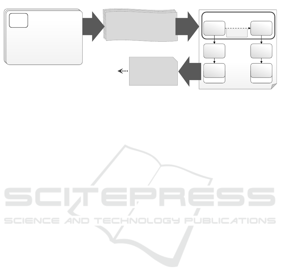
6 PROTOTYPE & VALIDATION
For automating the presented approach the logical
formulas have to be expressed as a logic program. For
the prototypical implementation and validation we
used the logic programming language PROLOG. For
modeling declarative deployment models, the cloud
standard TOSCA was chosen. For the prototype, the
TOSCA modeling tool Winery
3
and the problem de-
tection tool ProDec
4
are extended. We first describe
the mapping of the topology meta model to TOSCA,
then the system architecture and the validation.
6.1 Mapping to TOSCA
For the mapping of the presented meta model to
TOSCA, only the elements relevant to our approach
are considered. In TOSCA, the application structure
is modeled as Topology Template with Node Tem-
plates and Relationship Templates. The Node Tem-
plates represent the components and the Relationship
Templates their relations. This corresponds to the
topology and its components and relations of our meta
model. The semantics of the elements in the Topology
Template are determined by their types: Node Types
and Relationship Types. These types define Proper-
ties that can be used for adding additional information
to Node Templates and Relationship Templates, such
as login information or configuration details.
The types can be arbitrarily defined, but in the
TOSCA Simple Profile (OASIS, 2018) some norma-
tive types are defined that have to be available and in-
terpretable by each TOSCA-compliant runtime. This
includes, among others, the relationship types Hoste-
dOn and ConnectsTo. These normative types support
the definition of logical formulas because they form
the universal semantical basis. These are the basic el-
ements of TOSCA that are required to implement the
DC matching and topology adaptation.
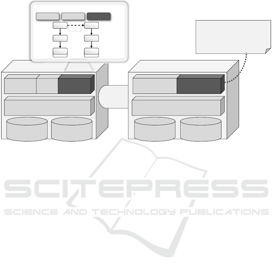
6.2 System Architecture
The prototype for the presented approach is an exten-
sion of two tools: The Winery is a graphical model-
ing tool for TOSCA. The Topology-ProDec is a tool
for detecting problems in topologies using PROLOG.
ProDec is extended for solution detection and thus re-
named to ToPS (Topology Problem and Solution De-
tector). In Figure 7 the enriched system architecture
is presented. The light grey components represent
3
https://github.com/OpenTOSCA/winery/releases/tag/
paper%2Fsolutionselectionandadaptation
4
https://github.com/OpenTOSCA/ToPS/releases/tag/
paper%2Fsolutionselectionandadaptation
the existing, while the dark grey components depict
newly developed system components.
Winery consists of the Backend and the Topology
Modeler. The UI for managing the TOSCA elements
is not shown. The Topology Modeler can be used to
model topologies as directed graphs. The Backend
offers a management component to access, add, mod-
ify, and delete TOSCA elements. In addition, it is
capable to import and export Cloud Service Archives
(CSARs). This is the standardized packaging format
that can be consumed by TOSCA runtimes. The Split-
ting & Matching functionality is used to restructure a
topology based on target labels attached to compo-
nents (Saatkamp et al., 2017).
In restructured topologies, problems can be de-
tected using the Problem Detector provided by ToPS.
First, the Topology Facts Generator generates PRO-
LOG facts based on a TOSCA topology. PROLOG
facts are atomic formulas that are always interpreted
with true. The pattern descriptions for problem de-
tection, including the PROLOG rules that formalize
the problem, are stored as markdown files. The Prob-
lem Detector applies all available problem rules to a
topology and provides all detected problems.
In the Topology Modeler, a user can select the
problem that shall be solved. Solution files are also
stored as markdown files and contain a textual de-
scription, a link to the pattern, the DCs as PROLOG
rules, and a link to the TA. All DCs, i.e., the PROLOG
rules, which link to the problem to be solved for a par-
ticular topology, are applied by the Solution Detector
to the topology and provides matching solutions. The
user can select the preferred one and the TA is exe-
cuted. A TA can be provided by an external service
or Winery. If it is provided by Winery, the TA Factory
resolves the requested algorithm and applies it to the
topology. Since many problems can be contained in a
topology and additional problems can arise after ap-
plying a solution, the problem detection and solution
detection is an iterative process.
6.3 Validation
For validating our approach, we expressed the log-
ical formulas presented in Section 5.2 as PROLOG
rules that can be interpreted based on given facts by
a PROLOG Interpreter. We used the SWI PROLOG
Interpreter and Library
5
. Since the logical formulas
in Section 5.2 comply with the restrictions described
in Section 5.3, the formulas can easily be transformed
into PROLOG rules. In the following, two PROLOG
rules are exemplary shown, the remaining rules can
be found in ToPS.
5
http://www.swi-prolog.org/
An Approach to Determine Apply Solutions to Solve Detected Problems in Restructured Deployment Models using First-order Logic
503
Winery Backend
TOSCA Elements
Repository
TOSCA Elements
Management
Topology Facts
Generator
ToPS
Problem
Detector
Topology Facts
Repository
Prolog Rules
Repository
sensitiveData:
true
Frontend-
OS
Java-
App
PHP-
WebApp
Backend-
OS
IaaS
location: ex location: in
Hyper-
visor
…
Splitting &
Matching
…
TA Factory
Split Detect Solve
Solution
Detector
ipSec(Component1,Component2) :-
host(Component1, H1, VM),
host(Component2, H2, VM).
…
Winery Topology Modeler
Figure 7: Enriched Winery and ProDec Architecture.
host (C , H , T ) : -
co m pon e ntO f Ty p e (H , T ) ,
ho s t in g S tac k ( S ),
memb e r ( H , S )
memb e r ( C , S ).
In Prolog “:-” represents → and the logical ∧ is ex-
pressed as “,”. Each rule ends with “.” and predicates,
functions, and constants start with lower case, while
variables with upper case letters. member/2 is a pre-
defined predicate in PROLOG to verify if an object
is contained in a list. This rule corresponds to the
logical formula defined in Section 5.2 and is used as
helper rule to express the rules for the DCs to deter-
mine the different applicable solutions. The DC rule
for the IPsec solution is therefore defined as follows:
ipSec ( C1 , C2 ) : -
host ( C1 , H1 , vm ),
host ( C2 , H2 , vm ).
Lets assume the facts representing the abstract topol-
ogy in Figure 6 are generated. The problem detector
queries the rules repository based on the problem rule
for the SECURE CHANNEL pattern as follows:
? - i ns e cu r e Pu b li c Co m mu n ic a t io n ( C1 , C2 ).
This query results true for C1 = PHP-WebApp and
C2 = Java-App. Based on this outcome, the rule
repository can be queried for suitable solutions for
these two components, i.e., all available DCs are
checked:
? - ipSec ( p h p W e b A p p , j a vaApp ).
In contrast to the query before, the terms are con-
stants. The variables in the rule serve as placeholders
and are automatically replaced. If this can be derived
from the facts, the PROLOG interpreter results with
true. Thus, the applicable TAs can be determined.
To realize the IPsec solution the VMs of the involved
components must be exchanged by VMs configured
to establish a VPN using IPsec. In addition, relations
between the two VMs are added because each VM
must know the endpoint of the other one.
7 RELATED WORK
Several approaches exist that use graph matching to
detect subgraphs in application architectures or de-
ployment models defined as directed graph to check
compliance rules, apply management operations, or to
refine and rewrite the graph (Krieger et al., 2018; Bre-
itenb
¨
ucher et al., 2014b; Breitenb
¨
ucher et al., 2014c;
Harzenetter et al., 2018; Guth and Leymann, 2018;
Arnold et al., 2007; Eilam et al., 2006). Guth and Ley-
mann (2018) apply patterns to architectural graphs.
These patterns are defined as graph fragments and
only one solution can be defined for one pattern.
Since the absence of elements is also important to
determine whether a DC is contained in a topology,
graph matching approaches are not sufficient for the
automated detection of matching DCs.
Various methods have been introduced for
pattern structure recognition in UML diagrams
based on design patterns. Kampffmeyer and
CLOSER 2019 - 9th International Conference on Cloud Computing and Services Science
504

Zschaler (2007), Kim and Lu (2006), as well as Kim
and Khawad (2007) formalized the pattern problem
to detect applicable patterns. In previous works,
we focused on the problem and context descriptions
of patterns to detect problems in deployment mod-
els (Saatkamp et al., 2019; Saatkamp et al., 2018). We
used this approach as basis to determine appropriate
solutions based on detected problems. Di Martino and
Esposito (2013) and Bergenti and Poggi (2002) detect
pattern solutions in existing UML models and the lat-
ter also gives hints for improvements based on the de-
tected patterns. However, they all focus on detecting
the solution in UML diagrams and focus on a single
pattern language. Taibi and Ngo (2013) introduced
the BPSL language to describe patterns based on first-
order logic. Just like the other approaches mentioned
before, only existing solutions in UML diagrams can
be detected. Fontana and Zanoni (2011) present a tool
for pattern detection and architecture reconstruction,
but only based on structural comparisons.
Fehling et al. (2012) show that their cloud com-
puting patterns can be extended with additional im-
plementation artifacts. This approach is only de-
scribed in the domain of cloud computing and only
focused on concrete artifacts as solution implemen-
tations. Falkenthal et al. (2014a, 2014b) introduced
a concept to document solutions for patterns in a
reusable manner and to assign criteria to select a cer-
tain solution. The presented approach applies the con-
cept to define solution implementations in a reusable
manner for adapting deployment models. Solutions
are selected based on defined DCs and are imple-
mented using algorithms that adapt the deployment
model in an automated manner.
8 CONCLUSION
In this paper we presented an approach (i) to deter-
mine appropriate solutions for problems in declarative
deployment models and (ii) to adapt the deployment
model accordingly in an automated manner. For this,
we demonstrated how first-order logic can be used to
determine the applicability of solutions to a particu-
lar deployment model by expressing the deployment
context (DC) required to apply a certain solution as a
logical formula. In addition, we showed how adap-
tation algorithms can be defined that operate at the
topology elements specified by the corresponding de-
ployment context to realize a solution in a deployment
model. This eases the solution selection and applica-
tion for declarative deployment models. We prototyp-
ically implemented the approach using the TOSCA
standard to model declarative deployment models and
the logic programming language PROLOG.
The presented approach is intended to be used
during design time. If a running application shall
be newly distributed, the deployment model can be
adapted and deployed while the running instance has
to be terminated. In future work, we plan to im-
prove the authoring process of DCs by a semantical
model for relation, component, and property types.
Furthermore, the implementation of adaptation algo-
rithms can be supported by code-generation based on
the previously defined deployment context on which
an algorithm can operate.
ACKNOWLEDGEMENTS
This work was partially funded by the BMWi projects
IC4F (01MA17008G) and SePiA.Pro (01MD16013F)
and the German Research Foundation (DFG) project
SustainLife (641730).
REFERENCES
Alexander, C., Ishikawa, S., and Silverstein, M. (1977). A
Pattern Language: Towns, Buildings, Construction.
Oxford University Press.
Ardagna, D., Di Nitto, E., Casale, G., Petcu, D., Mo-
hagheghi, P., Mosser, S., Matthews, P., Gericke, A.,
Ballagny, C., D’Andria, F., et al. (2012). Modaclouds:
A model-driven approach for the design and execution
of applications on multiple clouds. In Proceedings of
the 4th International Workshop on Modeling in Soft-
ware Engineering (MiSE 2012), pages 50–56. IEEE
Press.
Arnold, W., Eilam, T., Kalantar, M., Konstantinou, A. V.,
and Totok, A. A. (2007). Pattern Based SOA Deploy-
ment. In Proceedings of the Fifth International Con-
ference on Service-Oriented Computing, pages 1–12.
Springer.
Bergenti, F. and Poggi, A. (2002). Improving UML Designs
Using Automatic Design Pattern Detection, pages
771–784. World Scientific.
Bergmayr, A., Breitenb
¨
ucher, U., Ferry, N., Rossini, A.,
Solberg, A., Wimmer, M., and Kappel, G. (2018).
A Systematic Review of Cloud Modeling Languages.
ACM Computing Surveys (CSUR), 51(1):1–38.
Breitenb
¨
ucher, U., Binz, T., K
´
epes, K., Kopp, O., Leymann,
F., and Wettinger, J. (2014a). Combining Declarative
and Imperative Cloud Application Provisioning based
on TOSCA. In International Conference on Cloud En-
gineering (IC2E 2014), pages 87–96. IEEE.
Breitenb
¨
ucher, U., Binz, T., Kopp, O., and Leymann, F.
(2014b). Automating Cloud Application Management
Using Management Idioms. In Proceedings of the
Sixth International Conferences on Pervasive Patterns
and Applications (PATTERNS 2014), pages 60–69.
Xpert Publishing Services.
An Approach to Determine Apply Solutions to Solve Detected Problems in Restructured Deployment Models using First-order Logic
505

Breitenb
¨
ucher, U., Binz, T., Kopp, O., Leymann, F., and
Wettinger, J. (2013). Integrated Cloud Application
Provisioning: Interconnecting Service-Centric and
Script-Centric Management Technologies. In On the
Move to Meaningful Internet Systems, pages 130–148.
Springer.
Breitenb
¨
ucher, U., Binz, T., Kopp, O., Leymann, F., and
Wieland, M. (2014c). Context-Aware Cloud Applica-
tion Management. In Proceedings of the 4
th
Interna-
tional Conference on Cloud Computing and Services
Science, pages 499–509. SciTePress.
Carrasco, J., Cubo, J., and Pimentel, E. (2015). Towards a
flexible deployment of multi-cloud applications based
on TOSCA and CAMP. In Proceedings of the Third
European Conference on Service-Oriented and Cloud
Computing (ESOCC 2014), pages 278–286. Springer.
Eilam, T., Kalantar, M., Konstantinou, A., Pacifici, G., Per-
shing, J., and Agrawal, A. (2006). Managing the
configuration complexity of distributed applications
in Internet data centers. Communications Magazine,
44(3):166–177.
Endres, C., Breitenb
¨
ucher, U., Falkenthal, M., Kopp, O.,
Leymann, F., and Wettinger, J. (2017). Declarative vs.
Imperative: Two Modeling Patterns for the Automated
Deployment of Applications. In Proceedings of the 9
th
International Conference on Pervasive Patterns and
Applications, pages 22–27. Xpert Publishing Services.
Falkenthal, M., Barzen, J., Breitenb
¨
ucher, U., Fehling, C.,
and Leymann, F. (2014a). Efficient Pattern Applica-
tion: Validating the Concept of Solution Implementa-
tions in Different Domains. International Journal On
Advances in Software, 7(3&4):710–726.
Falkenthal, M., Barzen, J., Breitenb
¨
ucher, U., Fehling, C.,
and Leymann, F. (2014b). From Pattern Languages to
Solution Implementations. In Proceedings of the Sixth
International Conferences on Pervasive Patterns and
Applications (PATTERNS 2014), pages 12–21. Xpert
Publishing Services.
Fehling, C., Barzen, J., Falkenthal, M., and Leymann, F.
(2015). PatternPedia – Collaborative Pattern Identifi-
cation and Authoring. In Proceedings of PURPLSOC
(Pursuit of Pattern Languages for Societal Change).
The Workshop 2014., pages 252–284.
Fehling, C., Leymann, F., Retter, R., Schupeck, W., and
Arbitter, P. (2014). Cloud Computing Patterns: Fun-
damentals to Design, Build, and Manage Cloud Ap-
plications. Springer.
Fehling, C., Leymann, F., R
¨
utschlin, J., and Schumm, D.
(2012). Pattern-Based Development and Management
of Cloud Applications. Future Internet, 4(1):110–141.
Fontana, F. A. and Zanoni, M. (2011). A tool for design
pattern detection and software architecture reconstruc-
tion. Information sciences, 181(7):1306–1324.
Guth, J. and Leymann, F. (2018). Towards Pattern-based
Rewrite and Refinement of Application Architectures.
In Papers From the 12
th
Advanced Summer School on
Service Oriented Computing (SummerSOC’18), pages
90–100. IBM Research Division.
Harzenetter, L., Breitenb
¨
ucher, U., Falkenthal, M., Guth, J.,
Krieger, C., and Leymann, F. (2018). Pattern-based
deployment models and their automatic execution. In
11
th
IEEE/ACM International Conference on Utility
and Cloud Computing UCC 2018, 17–20 December
2018, Zurich, Switzerland, pages 41–52. IEEE Com-
puter Society.
Hohpe, G. and Woolf, B. (2004). Enterprise integration pat-
terns: Designing, building, and deploying messaging
solutions. Addison-Wesley Professional.
Kampffmeyer, H. and Zschaler, S. (2007). Finding the pat-
tern you need: The design pattern intent ontology. In
International Conference on Model Driven Engineer-
ing Languages and Systems, pages 211–225. Springer.
Kim, D.-K. and Khawand, C. E. (2007). An approach to
precisely specifying the problem domain of design
patterns. Journal of Visual Languages and Comput-
ing, 18(6):560–591.
Krieger, C., Breitenb
¨
ucher, U., K
´
epes, K., and Leymann,
F. (2018). An Approach to Automatically Check
the Compliance of Declarative Deployment Models.
In Papers from the 12
th
Advanced Summer School
on Service-Oriented Computing (SummerSoC 2018),
pages 76–89. IBM Research Division.
Lim, D.-K. and Lu, L. (2006). Inference of design pattern
instances in uml models via logic programming. In
11
th
IEEE International Conference on Engineering
of Complex Computer Systems, pages 10–29. IEEE.
Mahmud, R., Kotagiri, R., and Buyya, R. (2018). Fog Com-
puting: A Taxonomy, Survey and Future Directions,
pages 103–130. Springer Singapore.
Martino, B. D. and Esposito, A. (2013). Automatic recogni-
tion of design patterns from uml-based software doc-
umentation. In Proceedings of International Confer-
ence on Information Integration and Web-based Ap-
plications & Services, pages 280–289. ACM.
OASIS (2013). Topology and Orchestration Specification
for Cloud Applications (TOSCA) Version 1.0.
OASIS (2018). TOSCA Simple Profile in YAML Version 1.2.
Saatkamp, K., Breitenb
¨
ucher, U., Kopp, O., and Leymann,
F. (2017). Topology Splitting and Matching for Multi-
Cloud Deployments. In Proceedings of the 7th In-
ternational Conference on Cloud Computing and Ser-
vices Science, pages 247–258. SciTePress.
Saatkamp, K., Breitenb
¨
ucher, U., Kopp, O., and Ley-
mann, F. (2018). Application scenarios for automated
problem detection in tosca topologies by formalized
patterns. In Papers From the 12th Advanced Sum-
mer School on Service-Oriented Computing (Summer-
SOC’18), pages 43–53. IBM Research Division.
Saatkamp, K., Breitenb
¨
ucher, U., Kopp, O., and Ley-
mann, F. (2019). An Approach to Automatically De-
tect Problems in Restructured Deployment Models
based on Formalizing Architecture and Design Pat-
terns. Software-Intensive Cyber-Physical Systems.
Schumacher, M., Fernandez-Buglioni, E., Hybertson, D.,
Buschmann, F., and Sommerlad, P. (2006). Security
Patterns: Integrating Security and Systems Engineer-
ing. John Wiley & Sons, Inc.
Taibi, T. and Ngo, D. C. L. (2003). Formal specification
of design patterns - a balanced approach. Journal of
Object Technology, 2(4):127–140.
CLOSER 2019 - 9th International Conference on Cloud Computing and Services Science
506
