
The Modeling, Construction and Test Process of a 3D Printable Smart
Robot Rider
Jo
˜
ao Martin Gorte Jr.
1
, Witenberg Santiago Rodrigues Souza
2 a
, Artur Benevenutto Coelho
3
and L
´
ı Exequiel E. L
´
opez
3
1
Department of Electrical Engineering, Higher Education Institute of Brasilia, L2 Sul, Brasilia, Brazil
2
Postgraduate Program in Mechatronic Systems, University of Brasilia, Brasilia, Brazil
3
Department of Computer Engineering, Higher Education Institute of Brasilia, Brasilia, Brazil
Keywords:
Robot Design, Humanoid Robot, 3D Printing, Control Development, Automation.
Abstract:
This work aims to present a modeling procedure, manufacturing process, electronic design, programming and
communication system of a cyclist robot. The robot rider has the ability to ride a bicycle independently by
making decisions on shifts in balance that may occur during its motion by correcting its direction, balance
adjust, and stop. Robot decision-making processes were embedded in a shared control system of interactions
with the external environment by commands sent through wired serial link or radio frequency(RF), allowing
arm and leg- movements. This was achieved using a dual board synchronization powered by Atmel micro-
controllers (Arduino) and fed by information from an electronic gyroscope sensor, an accelerometer, and
remote radio frequency (RF) receptor. The final prototype was able to pedal from inertia accelerating gradually
to its full speed, stop the movement, and move its arms to recover balance.
1 INTRODUCTION
The possibilities of autonomous bicycles and self-
controlled or shared controlled robots able to maneu-
ver vehicles have been explored for years (Getz and
Marsden, 1995; Buss, 2000). It can be considered
a theme driven by urban mobility needs, reduction of
human physical effort and aiding people with disabili-
ties. Moreover, modern urban mobility demands echo
applications also motivate the green solution for liv-
ing in large cities. Thus, increasing capacity of robots
moving similarly to humans is essential for this pur-
pose.
One of the main goals in Robotics is the automa-
tion of tasks done by men (Pazos, 2013). Thus, one
of the goals in the field of Robotics is to perform
simulation of variety of movements, decision mak-
ing, hence human tasks performance. Despite intense
research activity, large scale implementation of such
tasks for daily life routine were not feasible in the
early robotics, due to high cost and early development
of auxiliary technology, causing to the field a moder-
ate development outside of industrial applications.
Moreover, development of such robotic systems
a
https://orcid.org/0000-0002-2208-7958
requires multidisciplinary knowledge. This work in-
volved mathematical modeling, mechanical drawing,
manufacture techniques in 3D printing, electronic de-
sign, micro-controller programming (Arduino, 2015;
Banzi, 2013) as well as access to auxiliary devices in-
cluding gyroscope, accelerometer, and RF system.
1.1 The Need for Autonomous Vehicles
and Free Space
In many urban areas, human effort can be measured
by the time spent on daily transit, from home to work
and vice-versa. Let the distance of 1km be the initial
reference to this example. In numerous cities, the ur-
ban traffic flows under the average speed of 15km/h, a
cyclist can also perform the same speed, and a pedes-
trian, which speed is about 3km/h, would take 20 min-
utes to perform the same 1km task. On a daily ba-
sis, time is a precious resource and should be spent
wisely . However, in rush hours (from 5 p.m. to 7
p.m.), for instance, places such as Brasilia, Brazil, a
car runs at 12km/h only which means that it takes 5
minutes to perform the 1 km distance. Now, at 1 hour
frame, a bicycle, with the above average speed, would
make 15km, while the car, only 12km in Brasilia, re-
Gorte Jr., J., Souza, W., Coelho, A. and López, L.
The Modeling, Construction and Test Process of a 3D Printable Smart Robot Rider.
DOI: 10.5220/0007773901650172
In Proceedings of the 16th International Conference on Informatics in Control, Automation and Robotics (ICINCO 2019), pages 165-172
ISBN: 978-989-758-380-3
Copyright
c
2019 by SCITEPRESS – Science and Technology Publications, Lda. All rights reserved
165

sulting in a delay of 15 minutes from a car to a cy-
clist who would have performed 15km for the same 1
hour. In addition, in cities such as Sao Paulo, where
the recorded average speed was below 8km/h, a bi-
cycle could outperform a car by 1 hour. The result
is one hour less of physically and mentally effort that
could be avoided when a bicycle is used (Lopes et al.,
2018).
Although bicycles are great candidate for enhanc-
ing urban mobility, the very action of balancing on a
two wheel vehicle is not an easy task, even for some-
one with no physical or mental disability. Depending
on the motor and sensory limitations of a person, the
task of riding a bicycle becomes even harder, if not
impossible. Additionally, a regularly used road lane
can be used safely by 6 bicycles and the space needed
for parking a bicycle takes one fifth of the amount of
space of a car. Furthermore, automobiles cost on av-
erage 10 to 50 times more than bicycles.
The bicycle is invaluable, yet is presents a com-
plex challenge to solve in robotics, specifically in
combination with a humanoid rider. However, suc-
cess in this project could possibly result in a new way
of transporting people, animals, and goods.
2 RELATED WORK
Over recent decades, the research on bicycle model-
ing resulted in many mathematical models of balance
and trajectory systems (Getz and Marsden, 1995).
The model validation is another task, performed by
analytic process and simulation to select the most rel-
evant model parameters (Buss, 2000). For instance,
(Buss, 2000) suggests torque and energy conservation
as parameters to be part of simulation. It increases
simulation confidence, given that, these parameters
may be used to determine the system’s stability for
both cyclist and bicycle (Getz and Marsden, 1995).
2.1 A Model for Rigid Bodies
During simulation phase, both cyclist and bicycle may
be represented in several means to reduce irrelevant
features. For example, (Getz and Marsden, 1995)
consider mass m and its height from the bicycle, row
angle α, direction angle from x axis, distance b be-
tween wheels, handle bar angle φ and its inertia J,
and a force µ which according to Getz simplifies the
model.
2.2 System Dynamics
Previous projects have often used Lagrange and
Euler-Lagrange methods (Sharma and Umashankar,
2006) to describe movements of a bicycle with
Denavit-Hartenberg algorithm for the joint connec-
tions of the bicycle. According to (Yetkin and et al,
2014) Lagrange’s equation describes energy conser-
vation defined as
L = T −U (1)
where T is the kinematic energy and U is potential
energy of the system. Another research used Newton-
Euler and Kane equations and virtual work princi-
ple (Shin and Lee, 2004). These methods, however,
are applied with simplification and restrictions lead-
ing to difficulties to reach acceptable results in real
time (Umashankar and Sharma, 2006).
2.3 Proposals without Artificial
Intelligence
The majority of proposals without artificial intelli-
gence contributed to the field by exploring which
variables are more relevant to the dynamic model
of a bicycle. The robot system used in (Yam-
aguchi, 2013)model has a remote control trajectory
and PID control system (Yamaguchi, 2013)) powered
PRIMER-V2 model (39cm height) by assisting its ini-
tial movement, its balance on the bicycle, and the
brake action. The system required a remote control
to determine its trajectory.
Most research seeks to solve both balance and
trajectory control challenges. Another end-goal is
developing an anti-collision system and a quality
measurement system of the road where the bicy-
cle passed (Stasinopoulos et al., 2015). In some
cases, researchers try to solve both problems of bal-
ance and trajectory only through validation on sim-
ulations (Sharma and Umashankar, 2006), (Bickford
and Davison, 2013), while other groups also built pro-
totypes in different scales.
(Yetkin and Ozguner, 2013) added to their model
and apparatus to simulate the gyroscope principle.
A disc added below the pedals axis on their model
spins to control the bicycle’s row angle, however, their
model does not have a direction bar. The model pro-
posed by (Bickford and Davison, 2013)presents mul-
tiple closed loops. Their work follows the same path
as many others who developed their work based on
Langrange’s method for dynamic equation and con-
sider the bicycle only, without a rider. As in the pre-
vious research projects mentioned above, the linear-
ity in this model presents limitations and depends on
ICINCO 2019 - 16th International Conference on Informatics in Control, Automation and Robotics
166

nearly constant linear velocities, while others could
start from inertia (Keo and Yamakita, 2009).
Some research, in addition to simulation also
built prototypes for real world tests. Among those
projects, several proposals used balance control meth-
ods such as PD or PID control (proportional integral
and derivative) applied to the direction bar, and gy-
roscope principle whether upon the the bicycle or be-
low it together with PD control (Wang et al., 2012).
There were also variable systems with linear parame-
ter (VLP) (Cerone et al., 2010), springs(Pandey et al.,
2015), and more complex systems such as slide con-
trol altogether with gyroscope principle. Those proto-
types were developed, in majority, from commercial
bicycles with further adaptations. However, there are
also those who built their bicycles in different scales
(Aphiratsakun and Techakittiroj, 2013). According to
(Aphiratsakun and Techakittiroj, 2013), controlling a
prototype by a micro-controller is a very difficult task.
2.4 Proposals with Artificial Intelligence
(AI)
Although first models with AI have been developed at
least two decades ago (Randløv and Alstrøm, 1998),
there were more work with traditional controllers. On
the other hand, the few number of works in AI, show
how the solutions are complex among these groups as
IA solutions claimed to be of simpler implementation
compared to traditional controllers. (Cook, 2004)) for
instance, sought demonstrating to be possible maneu-
ver the bicycle balanced along a trajectory using only
two neurons as controllers. Although the artificial
neural network (ANN) approach seems to be easier,
it has some drawbacks related to the number of iter-
ations it required until the first results are achieved.
Moreover, determining weight was very challenging,
thus leading to error most of the time. (Randløv
and Alstrøm, 1998)tried solving those issues combin-
ing reinforcement learning and calibration, yet their
approach required 5700 attempts for reasonable re-
sults. Without calibration, however, it would be nec-
essary 10
10
attempts. (Cam et al., 2013) revisited
Randløv and Alstrøm work on Python environment
Panda3D (Goslin and Mine, 2004) and PyBrain sup-
port (Schaul et al., 2010). Their results had shown
that the learning algorithm continuously dropped pre-
vious steps out, making it very sensitive to local min-
ima, which prevents the algorithm’s convergence for
balance and travel tasks. Convergence is the global
learning point for certain problems where reward is
maximized while penalty is minimized.
(Umashankar and Sharma, 2006) presented an in-
teresting method based on neuro-fuzzy adaptive con-
trol where fuzzy rules are applied upon a three layer
neural network. The first layer contains inputs, the
second layer has fuzzy rules, and the third layer is
the output. Their model is based on Euler-Lagrange
as the same presented in (Sharma and Umashankar,
2006), however, its new control provides more pos-
sibilities because of its learning capacity altogether
with fuzzy rules showed to be a better option than the
old method which did lose stability after ten seconds.
A complete work in computer graphics focused
on the state description of a cyclist-bike system and
presented a machine learning proposal for a charac-
ter able to perform several stunts on a BMX model
(Tan et al., 2014). In their work, it was not the bi-
cycle that was controlled, but the cyclist by an evolu-
tionary neural network. Due to the stunt’s complexity,
one cannot take into consideration bike dynamic only.
Rather, cyclist and bicycle as two rigid bodies con-
nected with six degrees of freedom using Jacobean
transpose matrix. The project also simulated power
transfer from feet to pedals, presenting excellent re-
sults on stunts performance during simulation. Other
research applied Deep Deterministic Policy Gradient
(DDPG) which is a deep learning approach to con-
trol balance and bicycle’s trajectory by minimizing
the system error (Chung et al., 2017).
3 METHODOLOGY
The initial phase was the creation of mathematical
models for arms and legs. The final step involved the
simulation of movements for arms and legs as well
as the first real world test for a pedal movement and
balance. The construction of the robot was designed
upon the use of renewable materials such as plas-
tic which reduced the manufacturing cost. The same
plastic was also used to built the 3D printer which has
refurbished pass-motors. Moreover, discarded pieces
of aluminum compose the frame of the bicycle and
the side shields on the legs of the robot.
3.1 Mathematical Modeling
The model followed the Homogeneous Transforma-
tion method. According to Figure 1, the robot has
three actuators (shoulder, arm, and elbow) for each
arm. Using the Kinematic diagram from Figure 1, the
relation from shoulder to hand can be expressed by
the homogeneous matrix equation in eq. 2 composed
by the rotation matrix and the displacement vector.
H(arm)
0
3
= H(shoulder)
0
1
H(arm)
1
2
H(elbow)
2
3
(2)
The Modeling, Construction and Test Process of a 3D Printable Smart Robot Rider
167
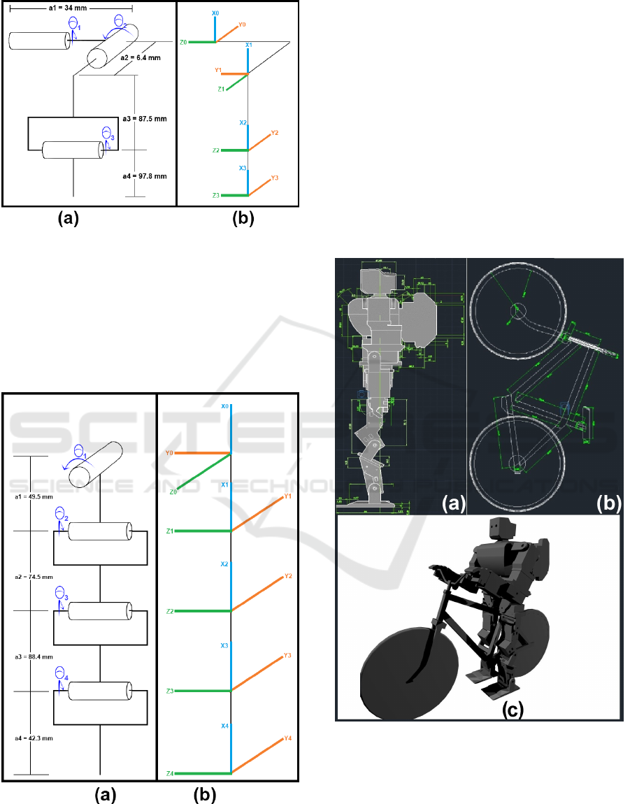
Figure 1: Arm kinematic diagram: a) link lengths ans rota-
tion angles, b) rotation frames.
Similarly, the mathematical model for the robot
leg was obtained from the kinematic diagram in Fig-
ure 2. The final homogeneous matrix expressed by
eq. 3 is the hip-to-foot relation.
H(leg)
0
4
= H(hips)
0
1
H(thigh)
1
2
H(knee)
2
3
H(ankle)
3
4
(3)
Figure 2: Leg kinematic diagram, a) link lengths and rota-
tion angles, b) rotation frames.
3.2 Mechanical Structure: Hardware
3.2.1 Modeling Each 3D Part
AutoCAD was used as the main graphic tool to design
the robot and bicycle. In the first stage, each part of
the robot was sketched, as seen in Figure 3,and later
sculpted to three dimensions. In the second stage, ev-
ery part was converted to STL file format to be printed
in 3D, Figure 4. Lately, the slicing were made on a
Reprap 3D printer software in order to set how many
layer of PLA would be used and also for time estima-
tion to construct each part. During construction stage,
tests had been performed in order to probe mechanical
properties of critical parts.
Figure 3: Robot (a) and its bicycle(b) both sketched in Au-
toCAD, (c) 3D model.
3.2.2 The Bicycle Construction
The acrylic wheels of the bicycle were estimated ac-
cording to the robot legs with 19cm diameter, 10mm
in thickness, and central hole of 1mm diameter. The
tire of each wheel was made of EVA tape(2.5 mm
ICINCO 2019 - 16th International Conference on Informatics in Control, Automation and Robotics
168
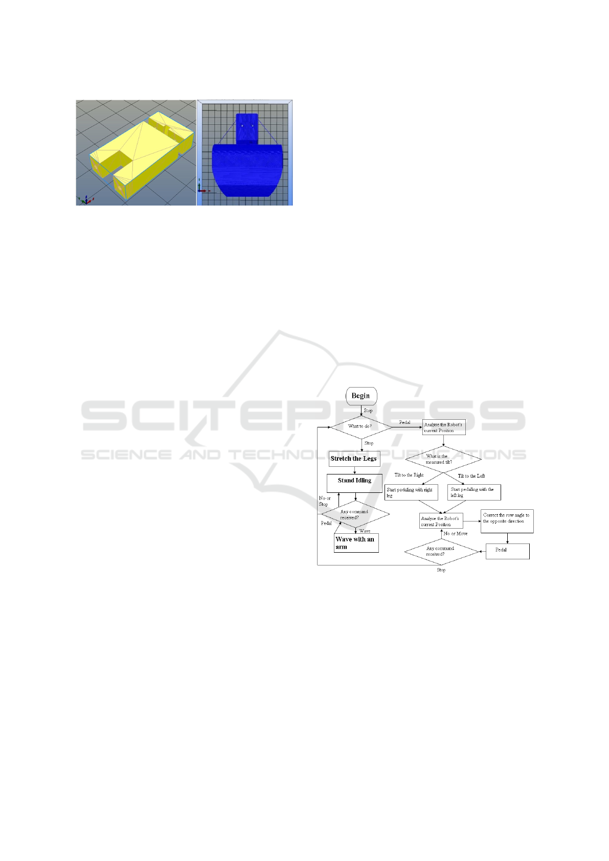
Figure 4: Parts in the printing process servo’s socket on the
left and the slicing process on the right.
thick). This tape has the purpose to increase grip be-
tween the wheel and the ground, and it also reduces
vibration on the composition. The main structure of
the bicycle is made of square bars of aluminum 6cm
thick, blend by aluminum soldering. A tripod was
manufactured to support the bicycle balanced dur-
ing tests. The transmission systems was built with a
sew machine rubber chain, connecting the 3D printed
gears of the bicycle. Pedals were challenging, for it
was made by using spin socket of an orthodontic ma-
chine had been couple on an 1.5mm diameter axis to
smooth movement and reduce grip.
3.2.3 The Power Supply
We used a specific battery of a hospital appara-
tus (pulmonary apparatus) to provide adequate cur-
rents and voltages for the entire circuit and motors.
This battery contains a circuit with fuses of protec-
tion against surges, under voltages and thermal fuses
for monitoring the temperature. We also manufac-
tured a board able to perform pulse width modulation
(PWM). Is was composed of a voltage regulator of
11V to 5V and a current limiter of 7A to 3A to supply
suitable for the robot. The board contains four 2n3055
voltage regulators and Zener diode for 6V voltage ref-
erence.
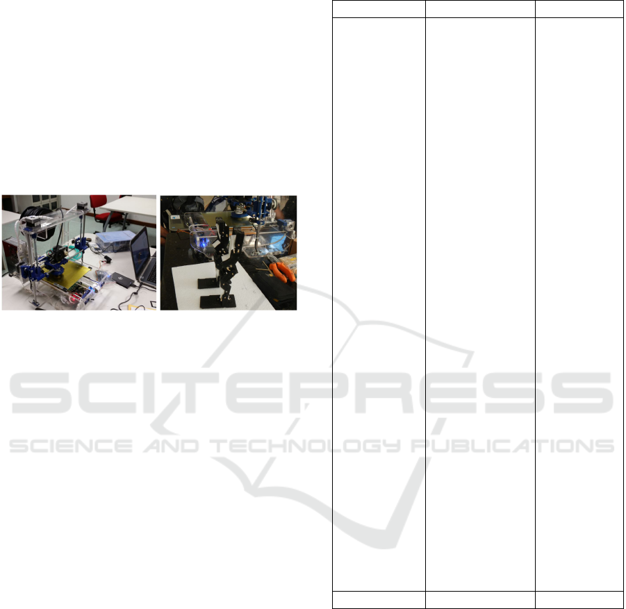
3.3 The Automated System Proposal
The algorithm was developed in C++ and deployed
in Arduino board Nano 3.0 with supporting libraries
servo.h and IR.h for servos’ control (Cormen and
et al, 2002; Sedgewick, 1998). Figure 5 show the
flowchart for the algorithm developed. The data from
gyroscope collected through serial protocol RS232
was used to calibrate the end angles of motion.
3.3.1 Detailed Movement
During the tests, the robot rider was able to perform
basic movements, such as pedaling, holding its feet
on the ground while riding, and moving its arms ac-
cording to the feedback from the accelerometer. We
divided the robot’s movements into stop mode and
motion. When it is in stop mode, the robot holds
its feet on the ground. In the transition from stop to
motion, one foot is set to back position prior to ped-
aling, which means the other foot remains the right
position to impulse the robot and overcome the iner-
tia. In intial tests, the arms stayed stretch horizontally
during real world tests a T-shape with the body. The
acceleration of the robot either increase speed or slow
down helping synchronization of both legs during the
required movements. When the robot starts the tran-
sition from movement to complete stop, it decelerates
and takes both legs off of the pedals stretching them
to touch the ground. Both movements, pedaling and
stopping can be remotely set.
Another featured movement built in the algorithm
is the emergency stop. When the gyroscope presents
skewed data, it triggers the movement, which indi-
cates that the robot may be falling. Thus, when the al-
gorithm detects this situation, the robot halts its pedal
function to enter in emergency mode, stretching the
arms and the legs.
Figure 5: Algorithm’s flowchart demonstrating the decision
steps the robot may take.
4 RESULTS
4.1 The 3-D Printing Phase
4.1.1 Process of 3D Printing
The majority of the parts of the robot (approximately
70%) were made by 3D printing. The 3D print-
ers were also assembled using reusable materials. It
The Modeling, Construction and Test Process of a 3D Printable Smart Robot Rider
169
works with plastic wires (3 mm or 1.75mm) made of
polylactic acid (PLA)which is melted to make the lay-
ers of the 3D printed parts.
After every part was finished by the printer, it was
measured in order to check if its dimensions would
met the designed project. Symmetry, and layer size
were measured. Some parts which should be coupled
to servomotor had density increased by 90% in order
to bear forces applied to them. Other parts were re-
designed for their size were not feasible to be printed
as a single piece or they had inner connections that
would not able accessed such as chest, battery case,
and head). Because of lack of precision for small
parts, some parts had to be adapted, such as the hands.
Figure 6: Printer and the first prototype printed legs.
4.2 The Assembling Process
A total 15 servo motors of 13N each with were used to
move all members of the robot. This phase involved
40% of the project budget. The servo motor were also
disassembled to add a 3mm steel axis to the opposite
side the servo axis.
4.2.1 The Bicycle Assembling
In the process of construction of the bicycle, we used
a 5mm solid aluminum bar to let the robot lighter and
balance the weight / power ratio. TIG welding was
used to reinforce the frame and with center of gravity
for the suitable robot. The wheels are made of acrylic
of 10 mm which were cut using the laser process to
stay closer to the CAD model.
After the assembling phase was complete, the pro-
totype, as well as its remote control, as shown in Fig-
ure 7, were ready for testing.
4.3 Simulation and Tests
Legs were tested to check their movement while ped-
aling. Tests had shown a balanced structure and
well synchronized servomotors. After first tests, cur-
rent measurements had shown consumption of 1.2A
for each leg, in which every servomotor consumed
400mA. On a standby state the robot consumed
370mA.
Table 1: Time spent on manufacturing each part of the bike
rider.
QUANTITY COMPONENT TIME
01 neck 36min
01 finger 1 47min
01 finger 2 47min
02 shin 1h 26min
01 foot 1 1h 49min
01 foot 2 1h 49min
01 neck base 1h 50min
02 thigh socket 2h 25min
02 ebow socket 2h 26min
02 ankle socket 2h 26min
02 forearm socket 2h 26min
02 knee base 2h 42min
02 foot base 2h 46min
02 elbow base 2h 51min
01 waist top 2h 54min
01 waist link 2h 57min
02 knee 3h 4min
02 foot socket 3h 4min
02 thigh 3h 11min
02 knee socket 3h 42min
02 femur socket 4h 4min
01 hand 1 4h 10min
01 hand 2 4h 10min
02 acrylic knee 4h 13min
02 forearm 4h 38m
02 waist socket 4h 43min
02 head 4h 44min
01 hips base 5h 4min
01 battery case 2 5h 7min
01 battery case 1 8h 31min
01 waist 8h 44m
01 hips 8h 48min
01 back 14h 42min
01 chest 22h 1min
51 TOTAL 149h 37min
The first pedaling movement had to have fine tun-
ing on tilt coupling, angular speed on each servomotor
and low rotation setup to perform the desired move-
ment.Figure 8 shows that the movements produced by
the system had a squared pattern,requiring additional
fine-tuning.
The algorithm cost required two Arduino boards
(salver and master) to slpit the legs routines from the
signals to the arms. A status signal allows the mas-
ter to know if the other Arduino is on stop mode,
movement, or whether an error occurred. Moreover,
the master board also receives the remote commands
from the joystick. When the system is ready, the mas-
ICINCO 2019 - 16th International Conference on Informatics in Control, Automation and Robotics
170
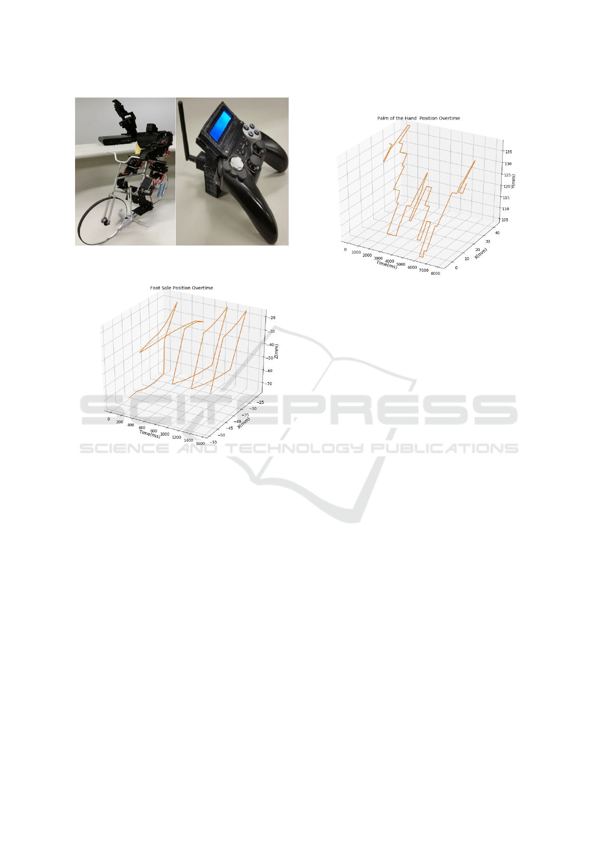
Figure 7: Assembled robot (second prototype) and joystick
remote control.
Figure 8: Foot movement simulation based on hip-to-foot
displacement vector.
ter Arduino set all initial parameters on the slaver
board to avoid code redundancy. After all parame-
ters set, the slaver board flags back a ready signal to
the master board. The communication between both
Arduinos allows the master to send stimuli signals to
the slaver board when it is in movement mode. When
it is in stop mode however, the master board sends
only one stop signal. If the master board stops work-
ing and the salver board is in movement mode, as it
will not receive the next stimuli, the emergency mode
will be triggered when the time for the next stimulus
is over. On the other hand, if the slaver Arduino board
stops working, the master board will notice it by the
status signal as it stopped receiving from the salver
board. Therefore, the master board will immediately
reset its own status and will keep trying to reestablish
the link with the other board until it succeed. After
reestablishing the link, the master board sends again
the initial parameters to the salver board.
In the simulation phase, the arms was in bent posi-
tion, with hands holding the steering bar as presented
on Figure 9.
Figure 9: Palm of the hand movement expressed by
shoulder-to-hand displacement vector.
5 CONCLUSIONS
This work presented the process of modeling, design,
construction and test of 3D printable robot rider. The
algorithm developed in C++ enable robot to move
its arms and legs to perform desired actions such as
pedaling, turning direction bar, start, and stop move-
ments. The mathematical model proved to reach the
proposed movement, although it required fine tuning
to smooth the movement.
All parts of the bike rider were designed to fit the
servomotors. In order to a better performance, a sec-
ond Arduino board had to be added to split the move-
ments from legs to arms.
Future work will include a free run test with-
out a tripod that supported the initial test of the
robot.Moreover, a forward kinematic system based on
neural network can also be compared to the current al-
gorithm.
ACKNOWLEDGEMENTS
The authors would like to thank the Institutional Pro-
gram for Initiation in Technological Development and
Innovation scholarship (PIBITI-CNPq) and the Scien-
tific Initiation Program at the Higher Education Insti-
tute of Brasilia- IESB. The authors also would like
to thank Dr. Masahiko Yamaguchi (Dr. Guero) and
Christina Driessen for their wonderful ideas.
The Modeling, Construction and Test Process of a 3D Printable Smart Robot Rider
171

REFERENCES
Aphiratsakun, N. and Techakittiroj, K. (2013). Au-
tonomous au bicycle: Self-balancing and tracking
control(ausub
2
). In IEEE International Conference on
Robotics and Biomimetics(ROBIO).
Arduino, S. A. (2015). Arduino. Arduino LLC.
Banzi, M. (2013). Primeiros passos com o arduino (First
steps with arduino). Novatec, Sao Paulo, 1st edition.
Bickford, D. and Davison, D. (2013). Systematic multi-
loop control for autonomous bicycle path following.
In 2013 26th IEEE Canadian Conference on Electri-
cal and Computer Engineering (CCECE), pages 1–5.
IEEE.
Buss, S. R. (2000). Accurate and efficient simulation
of rigid-body rotations. Journal of Computational
Physics, 164(2):377–406.
Cam, B., Dembia, C., and Israeli, J. (2013). Reinforcement
learning for bicycle control.
Cerone, V., Andreo, D., Larsson, M., and Regruto, D.
(2010). Stabilization of a riderless bicycle: A linear-
parameter-varying approach. In IEEE Control Syst.
Mag. Citeseer.
Chung, T. et al. (2017). In 2017 14th International Confer-
ence on Ubiquitous Robots and Ambient Intelligence
(URAI), pages 413–417. IEEE.
Cook, M. (2004). It takes two neurons to ride a bicycle.
Demonstration at NIPS, 4.
Cormen, T. and et al (2002). Algoritmos: teoria e pr
´
atica
(Algorithms: theory and practice). Elsevier, Rio de
Janeiro, 2nd edition.
Getz, N. H. and Marsden, J. E. (1995). Control for an au-
tonomous bicycle. In Proceedings of 1995 IEEE inter-
national conference on robotics and automation, vol-
ume 2, pages 1397–1402. IEEE.
Goslin, M. and Mine, M. R. (2004). The panda3d graphics
engine. Computer, 37(10):112–114.
Keo, L. and Yamakita, M. (2009). Controller design of an
autonomous bicycle with both steering and balancer
controls. In 2009 IEEE Control Applications,(CCA)
& Intelligent Control,(ISIC), pages 1294–1299. IEEE.
Lopes, R. R., Monteiro, L. S. G., de Miranda, R. R., and
de Souza Carvalho, C. (2018). (relat
´
orio anual de aci-
dentes de tr
ˆ
ansito - 2017 (annual report on traffic acci-
dents - 2017). Technical report, The Traffic Engineer-
ing Company (Companhia de Engenharia de Tr
´
afego).
Pandey, A., Mahajan, S., Kosta, A., Yadav, D., Pandey, V.,
Sahay, S., Jha, S., Agarwal, S., Bhise, A., Kumar, R.,
et al. (2015). Low cost autonomous navigation and
control of a mechanically balanced bicycle with dual
locomotion mode. In 2015 IEEE International Trans-
portation Electrification Conference (ITEC), pages 1–
10. IEEE.
Pazos, F. (2013). Automacao de Sistema e Robotica (Sys-
tem Automation and Robotics). Axcel, Sao Paulo, 1st
edition.
Randløv, J. and Alstrøm, P. (1998). Learning to drive a
bicycle using reinforcement learning and shaping. In
ICML, volume 98, pages 463–471.
Schaul, T., Bayer, J., Wierstra, D., Sun, Y., Felder, M.,
Sehnke, F., R
´
C1/4ckstie
´
C, T., and Schmidhuber, J.
(2010). Pybrain. Journal of Machine Learning Re-
search, 11(Feb):743–746.
Sedgewick, R. (1998). Algorithms in C: parts 1-5. Addison
Wesley Longman, New York, 3rd edition.
Sharma, H. D. and Umashankar, N. (2006). A robotic model
(robi) of autonomous bicycle system. In 2006 In-
ternational Conference on Computational Inteligence
for Modelling Control and Automation and Interna-
tional Conference on Intelligent Agents Web Tech-
nologies and International Commerce (CIMCA’06),
pages 107–107. IEEE.
Shin, J.-C. and Lee, C.-W. (2004). Rider’s net moment esti-
mation using control force of motion system for bicy-
cle simulator. Journal of robotic systems, 21(11):597–
607.
Stasinopoulos, S., Zhao, M., and Zhong, Y. (2015). Hu-
man behavior inspired obstacle avoidance & road sur-
face quality detection for autonomous bicycles. In
2015 IEEE International Conference on Robotics and
Biomimetics (ROBIO), pages 2121–2126. IEEE.
Tan, J., Gu, Y., Liu, C. K., and Turk, G. (2014). Learning
bicycle stunts. ACM Transactions on Graphics (TOG),
33(4):50.
Umashankar, N. and Sharma, H. D. (2006). Adaptive neuro-
fuzzy controller for stabilizing autonomous bicycle. In
2006 IEEE International Conference on Robotics and
Biomimetics, pages 1652–1657. IEEE.
Wang, L. X., Eklund, J. M., and Bhalla, V. (2012). Sim-
ulation & road test results on balance and directional
control of an autonomous bicycle. In 2012 25th IEEE
Canadian Conference on Electrical and Computer
Engineering (CCECE), pages 1–5. IEEE.
Yamaguchi, M. (2013). Cyclist robot able to ride
a bicycle (original title in japanese). htt p :
//ai2001.i f de f . jp/primer V 2/primer V 2.html.
Accessed on January 14, 2019.
Yetkin, H. and et al (2014). Gyroscopic stabilization of an
unmanned bicycle. In American Control Conference.
Yetkin, H. and Ozguner, U. (2013). Stabilizing control of an
autonomous bicycle. In Control Conference (ASCC).
ICINCO 2019 - 16th International Conference on Informatics in Control, Automation and Robotics
172
