
Smart Wheelchairs: Using Robotics to Bridge the Gap between
Prototypes and Cost-effective Set-ups
Matthew Aquilina
a
, Marvin K. Bugeja
b
and Simon G. Fabri
c
Department of Systems and Control Engineering, University of Malta, Msida, MSD 2080, Malta
Keywords:
Smart Wheelchair, Assistive Technology, ROS, Autonomous Navigation, Mapping, Electronic Hardware
Design.
Abstract:
Wheelchairs have improved the lives of many people with limited mobility. Yet, to this day, conventional
wheelchairs are still not a viable option for mobility independence in cases of people with severe weakness
or poor coordination e.g. Amyotrophic Lateral Sclerosis (ALS). Smart wheelchairs (SWs) overcome many
of these limitations by adding an extra layer of intelligence to the system. SWs have so far remained mostly
inaccessible to the general public, due to a limited market presence and steep costs. This paper thus presents the
design and implementation of a novel SW which makes the upgrade of a commercially available motorised
wheelchair to a SW a much simpler process. The system is a complete implementation offering low-level
hardware control, a specialised ROS architecture and autonomous navigation algorithms allowing shared user
control or fully-autonomous movement. Contrary to most other published works, the focus of this paper is
to implement a fully-featured working prototype with minimal hardware complexity and an efficient modular
software development environment. Initial practical tests in typical use scenarios showcased the successful
operation of the complete system. The developed prototype SW has the potential to restore autonomy to
people who are unable to use conventional or powered wheelchairs.
1 INTRODUCTION
Wheelchairs have been around since the 17th cen-
tury. Initially, these models all required the user or
a carer to manually propel the wheelchair. Designs
for Powered Wheelchairs (PWs) appeared in the early
20th century. PWs allow the user to control move-
ment of the motorised wheelchair through a joystick.
PWs and the more conventional manual wheelchairs
are the most popular kinds of wheelchairs in use today
(Simpson et al., 2008).
Conventional PWs provide mobility to many peo-
ple with special needs or to those who cannot walk
unaided. However, people with severe weakness who
cannot direct a joystick (e.g. individuals with ALS)
or people with very poor coordination (e.g. Cerebral
Palsy) cannot use PWs (Simpson et al., 2008). Per-
sons in such a situation often end up dependent on
others to propel their wheelchair.
The concept of a Smart Wheelchair (SW) started
a
https://orcid.org/0000-0002-4039-1398
b
https://orcid.org/0000-0001-6632-2369
c
https://orcid.org/0000-0002-6546-4362
taking shape in the 1980s (Simpson, 2005). A SW
is an upgraded form of PW to which a number of
sensors and computing units are attached to enable
semi-autonomous or autonomous modes of operation
(Leaman and La, 2017). The SW operates via nav-
igation algorithms, such as those for path-planning
and obstacle avoidance, to achieve autonomous and
safe mobility. These systems, coupled with some
simple input mechanisms (such as a touchscreen or
voice command) can compensate for a user’s lack of
coordination or weakness. SW technology has pro-
gressed greatly worldwide, with designs consisting of
multiple sensors and complex algorithms. However,
despite many sophisticated models being developed,
practically none of them have made it to the commer-
cial market (Leaman and La, 2017).
This paper aims to challenge this state of affairs by
presenting a novel and inexpensive design methodol-
ogy by which a standard commercially available PW
could be upgraded to SW level, both in technology
and in autonomy. The hardware used is easily ac-
cessible, and all software is coded using open-source
frameworks. To demonstrate its applicability, a SW
platform was designed and retrofitted on top of a sim-
Aquilina, M., Bugeja, M. and Fabri, S.
Smart Wheelchairs: Using Robotics to Bridge the Gap between Prototypes and Cost-effective Set-ups.
DOI: 10.5220/0007796801810189
In Proceedings of the 16th International Conference on Informatics in Control, Automation and Robotics (ICINCO 2019), pages 181-189
ISBN: 978-989-758-380-3
Copyright
c
2019 by SCITEPRESS – Science and Technology Publications, Lda. All rights reserved
181

ple and inexpensive PW available on the market, the
process of which is detailed in this paper. Both semi-
autonomous and fully-autonomous navigation algo-
rithms were deployed successfully on this prototype,
demonstrating the capabilities of the build.
The paper is organised in the following manner.
Section 2 contains a brief review of related work in
the literature. Section 3 details the process followed
to upgrade the hardware systems to SW level start-
ing from the standard PW frame. Section 4 builds on
Section 3 by going into further detail on the support-
ing software infrastructure. Section 5 expands on the
navigation algorithms, and Section 6 details and dis-
cusses the results obtained, followed by conclusions
in Section 7.
2 RELATED WORK
Generally, SWs in development fall into one of two
categories: navigation aids or fully-autonomous ve-
hicles. Both use similar sensors and hardware to
achieve their aims; the difference lies in the software
and algorithms they use.
2.1 Wheelchairs with Navigation Aids
Wheelchairs with navigation aids aim to enhance the
user’s mobility without completely ignoring the user’s
input when navigating. One of the oldest and most
well-developed examples is the NavChair (Levine
et al., 1999). This chair could use its on-board Vec-
tor Field Histograms (VFH) (Borenstein and Koren,
1991) and Virtual Force Field (VFF) (Borenstein and
Koren, 1989) obstacle avoidance methods to guide the
wheelchair in the general direction the user indicates
through a joystick. Similarly, Carlson and Demiris
(2012) present another study where the wheelchair
acts to help a user reach a destination inferred through
a joystick. This system uses a camera localisation
system, laser rangefinder and ultrasonic sensors, re-
sulting in a much better picture of the environment
than that obtained through ultrasonic sensors alone.
Many other systems (Nasri et al., 2016; Leaman et al.,
2016; Cavanini et al., 2014) have been developed with
features designed to complement a user’s guiding in-
put. However, all of these studies typically have one
or more obstructive hardware limitations, such as de-
pendence on a laptop rather than an embedded PC,
a prohibitively expensive sensor suite or the require-
ment of a specific wheelchair brand for the software
to operate.
2.2 Autonomous Wheelchairs
Fully-autonomous SWs depend almost completely on
their software and sensory systems for navigation.
Some SWs, such as in Echefu et al. (2017), plan
paths in advance on a map using planners such as
the A* (Hart et al., 1968) or D*Lite (Koenig and
Likhachev, 2002) algorithms. With the plan com-
plete, the wheelchair is guided through the path, using
a local obstacle avoidance algorithm (such as VFH
(Borenstein and Koren, 1991) or Dynamic Window
Approach (DWA) (Fox et al., 1995)) to navigate ob-
stacles unmarked on the map. Others, such as Kin-
para et al. (2011), navigate by following a desig-
nated carer or group of carers. This is made possible
through a complicated system of laser rangefinders
and a camera acting as people/group detectors. Addi-
tionally, fully-autonomous modes can be used to en-
hance maps with more in-detail features. Hemachan-
dra et al. (2011) achieve this through a SW which
follows a tour guide and draws up a map using laser
rangefinders, whilst also tagging different rooms with
information it infers through listening to the tour
guide. Generally, such advanced features require a
larger sensor suite, resulting in a more complicated or
expensive design.
In this project, both navigation aid and au-
tonomous functionalities were implemented onto the
wheelchair. A combination of the VFH+ (Ulrich and
Borenstein, 1998) and A* (Hart et al., 1968) path
planners were utilised to achieve these functions. A
laser rangefinder was used as the primary method
of obstacle detection, complemented by a set of ul-
trasonic sensors. Navigation was managed through
wheel encoders for both localisation and closed-loop
speed control. By keeping the sensor suite small, the
developed SW retains a similar footprint to its origi-
nal PW design, whilst providing enough information
about the environment to navigate safely. The devel-
oped software is implemented using an ROS (ROS,
nde) backbone, keeping the system lean, modular and
efficient whilst providing an easy-to-use Python de-
velopment environment.
3 TECHNICAL HARDWARE
DESIGN
One of the main hindrances to SW adoption is the
difficulty of mounting the required technology onto
a standard powered wheelchair frame. This section
provides an overview of the procedure adopted to ef-
ficiently upgrade our PW to a SW.
ICINCO 2019 - 16th International Conference on Informatics in Control, Automation and Robotics
182
3.1 Powered Wheelchair Upgrade
The Surace 715 Magic (Figure 1) was selected as the
PW base (Surace, nd). This wheelchair came with
two 24V geared DC motors along with a battery pack,
motors driver and a joystick. The controller elec-
tronics were closed-source and had to be removed
completely, leaving only the motors and battery to be
used by the SW. This situation also applies to the vast
majority of standard PWs that are available commer-
cially.
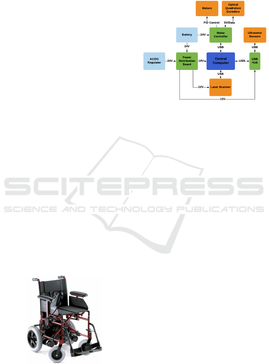
3.2 System Architecture
The architecture of the new system installed on the
wheelchair is shown in the block diagram of Figure 2.
3.2.1 Computer and Motor Controller System
A computer was placed on board the wheelchair,
in order to act as the central communication point
whilst executing algorithms. A compromise needed
to be achieved between size and processing capabil-
ity/speed. The Intel NUC mini PC (Intel, nd) offered
the best balance. These PCs are available with a range
of options, allowing one to either prioritise on extra
capability or a lower budget.
Communicating data to and from the computer
was facilitated through the use of USB ports. Thus,
the motor controller selected for the SW needed
to have some way to transfer and receive data via
USB. Rather than introducing a converter or mi-
croprocessor unit to achieve USB communication,
the USB-compatible MCP233 Advanced Motor Con-
troller (BasicMicro, nd) was selected instead. This
controller offered the capability of driving both mo-
tors simultaneously, in-built Proportional Integral
Derivative (PID) code and several mixed functionality
pins for sensor interfacing, brake driving etc.
Figure 1: The standard powered wheelchair (Surace, nd).
Central
Computer
Motor
Controller
Power
Distribution
Board
Laser Scanner
Ultrasonic
Sensors
Motors
Optical
Quadrature
Encoders
Battery
USB
Hub
24V
19V
USB
USB
12V
12V
USB
24V
PID Control 5V/Data
AC/DC
Regulator
24V
24V Supply
5V Regulator
12V Regulator
19V Regulator
Sensor
Expansions
Computer
Laser Scanner,
USB Hub
USB
Figure 2: Hardware system block diagram.
3.2.2 Sensors
The sensors chosen for the system included a Hokuyo
240° laser rangefinder (Hokuyo, nd), a set of ul-
trasonic sensors (Maxbotix, nd) and 1024 ppr opti-
cal quadrature wheel encoders (Hengstler, nd). The
laser rangefinder was mounted at the front of the
wheelchair on an extended arm in order to keep its
line-of-sight clear of obstructions. The ultrasonic sen-
sors were mounted in a ring around the wheelchair,
attached directly to the chassis. The wheel encoders
were attached directly to each motor shaft by extend-
ing the shafts through the motor caps. The resulting
setup had an effective angular resolution of 0.00275°.
Given the large number of sensors (and other devices
requiring USB ports), two USB hubs were used to
expand the ports available; one unpowered and one
powered (through a 12V power supply).
3.2.3 Power Distribution System
With all devices accounted for, the different voltages
required for the system were: 19V for the computer,
12V for the USB hub and laser rangefinder, 5V for
the encoders and 24V for the motors. A simple reg-
ulatory circuit was custom-built to provide all the re-
quired regulated voltages from the unregulated 24V
wheelchair battery. Additionally, a switchover system
was designed and implemented to allow all electron-
ics (except the motors and controller) to be powered
via an external AC wall plug. This allowed the devel-
oper to continue using the computer and sensors, even
while the battery was charging. The motors them-
selves were powered solely from the MCP233 con-
troller. The controller was connected to the battery
through a custom-designed protection system incor-
porating in-rush current prevention, fuses and a re-
verse energy recovery diode.
Smart Wheelchairs: Using Robotics to Bridge the Gap between Prototypes and Cost-effective Set-ups
183
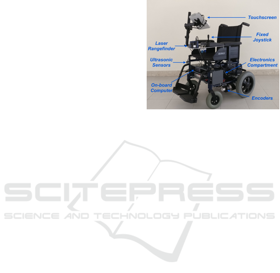
3.3 Final Implementation
Three methods of user-input were made available on
the wheelchair. A fixed joystick (USB) was mounted
next to the wheelchair’s arm rest, along with a wire-
less remote control which emulated the fixed joy-
stick’s functionality at a distance. This remote control
was attached to the system via the mini PC’s in-built
Bluetooth module. Additionally, a touchscreen mon-
itor was mounted at the front of the chair, which al-
lowed the user to directly interface with the computer
operating system, navigation controls and system di-
agnostics.
All electronics were housed within a two-level
PVC compartment mounted at the bottom of the chair.
The bottom level was dedicated completely to the
power and motor controller units, while the top level
was occupied by the computer and USB hubs. Due
to the large number of high power components, vari-
ous space optimisations were introduced such as fix-
ing components to the ceiling of the compartment or
connecting cables to busbars. The complete SW is
shown in Figure 3. By opting for USB connectivity,
and by designing custom-made power solutions, the
price of the upgrade was kept to a minimum.
4 SOFTWARE
INFRASTRUCTURE
With the hardware shell complete, the software driver
systems had to be built before any navigation algo-
rithms could be employed.
4.1 Software Platform
4.1.1 ROS
The primary decisions were to select which soft-
ware platform, framework and language to use for
the system. The ideal solution for the wheelchair
was found in Robot Operating System (ROS) (ROS,
nde) (specifically version Lunar Loggerhead). ROS
provides many tools and services which allow one to
build a whole web of interconnected programs work-
ing in a parallel manner whilst sharing data between
them.
The parallelised system, along with a host of well-
built and open-source libraries and development tools,
made ROS ideal to act as the software base architec-
ture for the wheelchair. Simulations of the algorithms
used on the SW were carried out directly in ROS, fol-
lowing which they were imported to the system on-
board the wheelchair PC.
Figure 3: The complete Smart Wheelchair.
4.1.2 Platform and Language
Ubuntu Linux (specifically version 16.04 LTS)
(Ubuntu, nd) was selected as the operating system
for the wheelchair, being one of the most popular
and user-friendly Linux distributions available. The
whole system was coded in Python 2.7, due to its ex-
tensive ROS support and availability of open-source
mathematical, graphing and multithreading libraries.
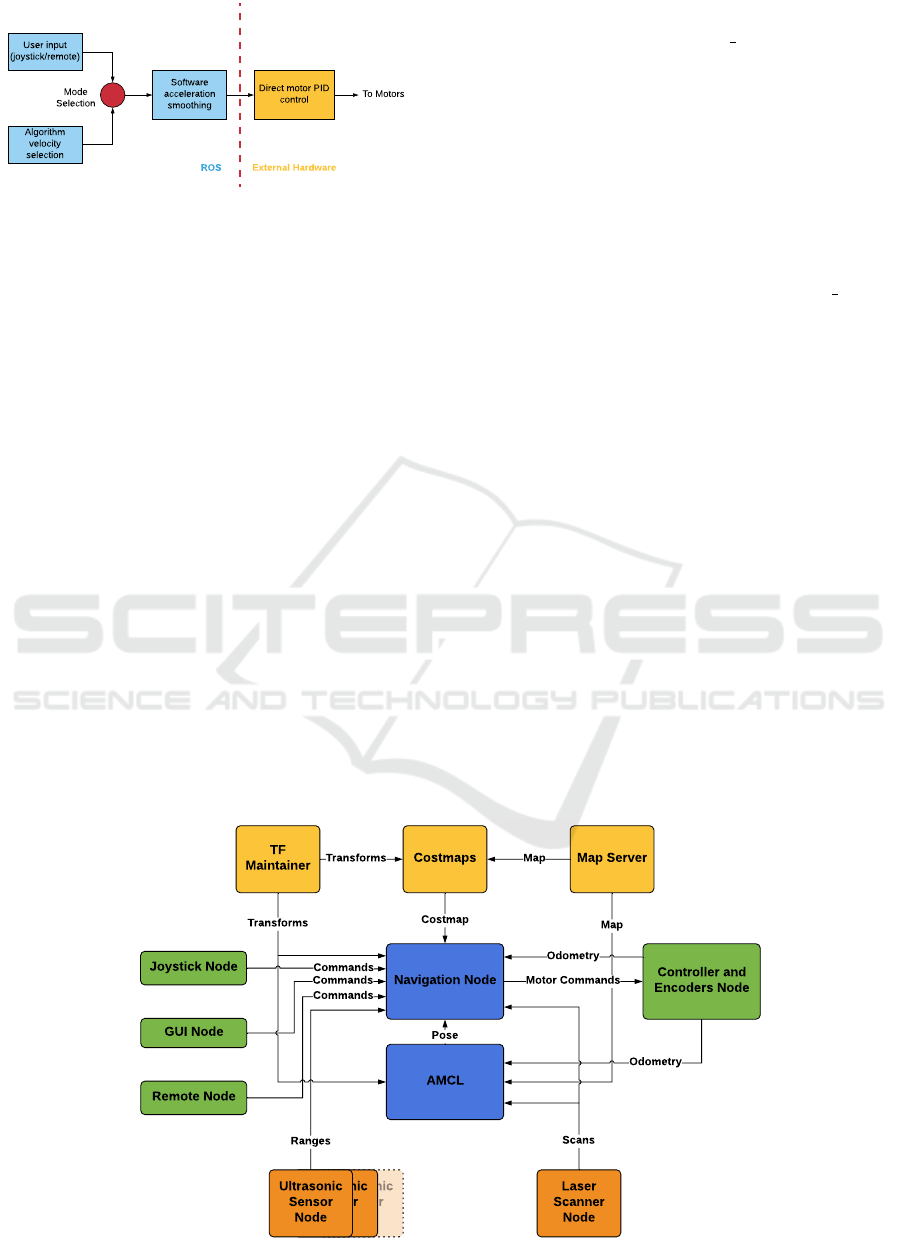
4.2 Low-level Setup
Some low-level configurations and tuning needed to
be applied before integrating the ROS node system.
The encoders were connected directly to the motor
controller which read the encoder pulses for closed-
loop speed control. Additionally, the controller sent
the raw encoder counts to the computer via USB,
where standard dead-reckoning calculations were per-
formed to turn this data into a source of odometry.
The controller’s internal PID system needed to be
tuned with appropriate gain values. The PID control
was set to reach the targeted velocity value as quickly
as possible. Instant acceleration, however, was not the
desired behaviour on the wheelchair; this would have
led to a very uncomfortable ride for the user. Thus, ac-
celeration was regulated by another P controller pro-
grammed into ROS. This controller took in the desired
target velocity and limited the change from the cur-
rent velocity within reasonable limits, before sending
this adapted velocity to the motor controller. In this
way, the acceleration was made smoother, and abrupt
starts or stops were kept to a minimum. Additionally,
immediate control of the motor speeds was still avail-
able in emergencies, thanks to the rapid response of
the hardware PID system. The velocity control proce-
dure is presented graphically in Figure 4.
ICINCO 2019 - 16th International Conference on Informatics in Control, Automation and Robotics
184
To Motors
Software
acceleration
smoothing
Direct motor PID
control
User input
(joystick/remote)
Algorithm
velocity
selection
ROS
External Har dware
Mode
Selection
Figure 4: Velocity Smoothing Procedure.
4.3 Node Setup and Integration
All sensor and input streams were separated into dif-
ferent ROS nodes, resulting in the structure shown in
Figure 5.
4.3.1 Mapping and Costmapping
When using the SW in an indoor environment, maps
can help in localisation and allow the SW to pre-
plan paths through its environment. Mapping in this
system was facilitated through the use of the ROS
Gmapping package (ROS, ndc). This uses a Rao-
Blackwellised particle filter (openSLAM, nd) to fuse
laser and odometry data together to form a well-
dimensioned map. To build this map, the wheelchair
was slowly driven around the selected area, while data
from the laser rangefinder and encoders was gathered.
These were then fed to the Gmapping package, which
translated them into an occupancy grid map. An ex-
ample of such a map is provided in Figure 10. Before
being able to produce accurate maps, a lengthy pro-
cedure of manual parameter tuning (number of parti-
cles, linear/angular update intervals and range) had to
be followed to correctly fit the Gmapping system to
the SW hardware. The Costmap 2D (ROS, ndb) ROS
package was used to inflate obstacles on the map with
the wheelchair’s radius.
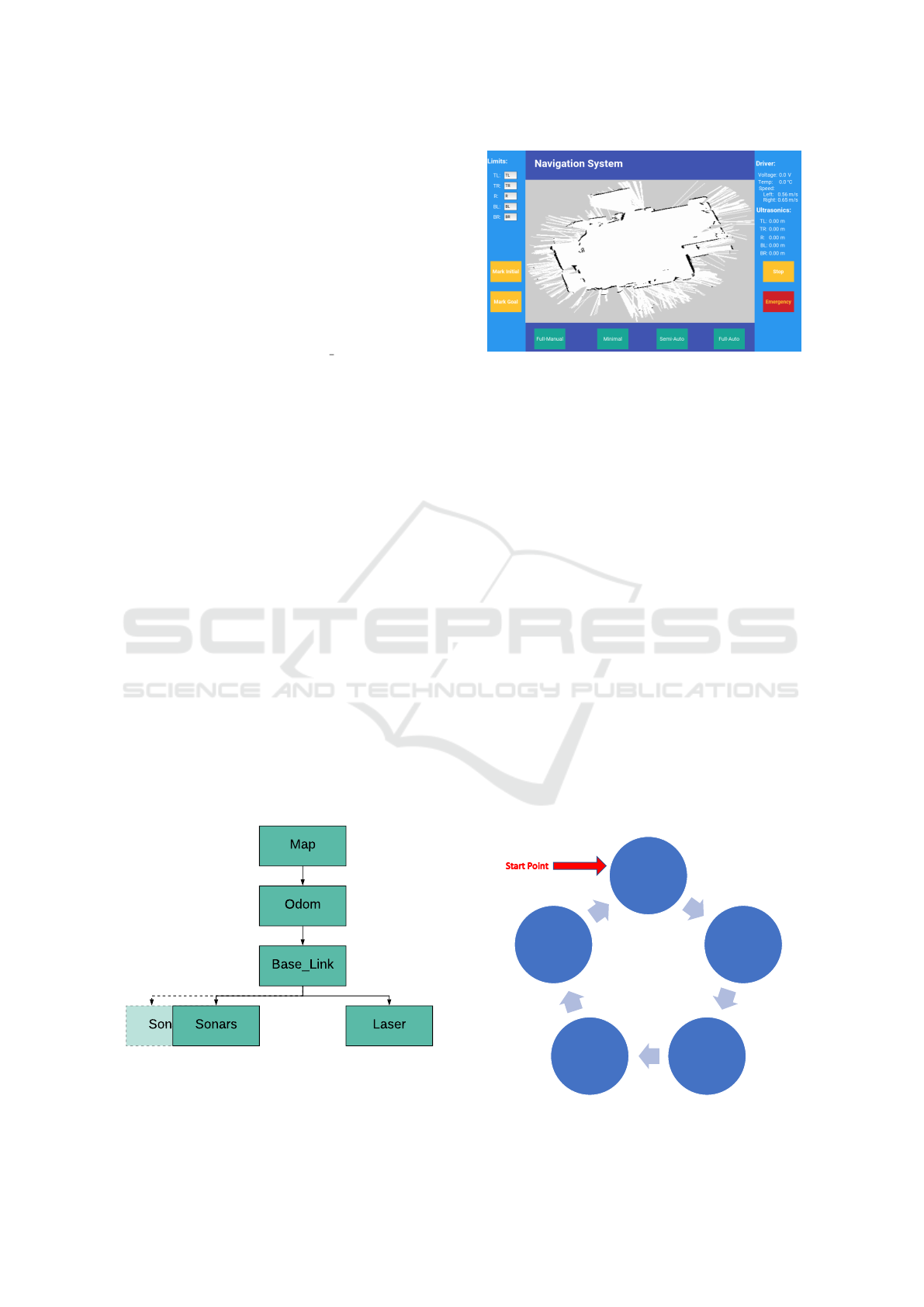
4.3.2 TF
The TF package from ROS (ROS, ndf) was used to
keep track of the many coordinate systems present on
the wheelchair. The hierarchical structure in Figure 6
was built through this package. The bottom relation
in this structure was the positioning of each sensor
with respect to the wheelchair centre (Base Link in
Figure 6). These relations were fixed (i.e. the laser
rangefinder was always at a fixed distance away from
the centre of the wheelchair). This information was
used when determining the wheelchair navigational
paths (to be described in Section 5).
Along with these hardware levels, TF also man-
aged the link between a map, the odometry system
and the wheelchair position. Odometry was taken
care of entirely by the wheel encoders, which ref-
erenced the distance travelled from a fixed point.
When using a map, the system needed to define
where the wheelchair was, relative to the map. To
handle this, the Adaptive Monte Carlo Localisation
(AMCL) (ROS, nda) package (unmodified) from ROS
was used. This package handled publishing the trans-
form between the Odom and Map transforms (Figure
6) and hence took care of positioning the wheelchair
on the map. This package does not only rely on en-
coder readings to position the wheelchair on the map
due to their inherent drift issues. Instead, AMCL uses
a particle filter to stochastically fuse laser scans and
encoder readings and compare these readings with the
Ultrasonic
Sensor
Node
Ultrasonic
Sensor
Node
Navigation Node
Controller and
Encoders Node
GUI Node
AMCL
Laser
Scanner
Node
Joystick Node
Map ServerCostmaps
TF
Maintainer
Ultrasonic
Sensor
Node
Remote Node
Costmap
Map
Scans
Pose
Odometry
Map
Ranges
Commands
Commands
Transforms
Odometry
Motor Commands
Commands
Transforms
Figure 5: ROS system node diagram.
Smart Wheelchairs: Using Robotics to Bridge the Gap between Prototypes and Cost-effective Set-ups
185
current map. This helped the SW localise with the
map as a reference point, thus mitigating considerably
the errors introduced by encoder dead-reckoning.
4.3.3 Input/Output Device Interfacing
Each sensor and input device in the system was as-
signed a dedicated node (except the encoders, which
were bundled with the motor controller). These nodes
managed the basic processing required to translate
data in and out of the system. The laser rangefinder
was taken care of by the ROS ‘urg node’ (ROS, ndg)
package which translated laser scans into fixed ar-
rays of distance measurements and angles. The ul-
trasonic sensors were handled through custom-made
serial nodes, which picked up range readings from the
sensors at fixed rates. The joystick/remote returned
deviations from their centre when actuated. These
were translated to angular/magnitude changes and
sent to the navigation system for processing. For the
touchscreen, a Graphical User Interface (GUI) was
constructed using Kivy (Kivy, nd), an open-source
GUI Python library. The GUI was populated with
diagnostics and tools, allowing a user to control the
navigation system (Section 5) and tweak its parame-
ters. Additionally, the touchscreen allowed a user to
switch navigation modes and view the wheelchair po-
sition on the map. A typical view of the GUI is shown
in Figure 7.
5 NAVIGATION ALGORITHMS
With both the software and hardware infrastructures
complete, the actual intelligent navigation algorithms
were developed and implemented on the system (as
the Navigation Node of Figure 5).
Sonars
Map
Base_Link
Odom
Sonars Laser
Figure 6: Transformation tree.
Figure 7: Custom-made GUI showing mode selection, on-
line information and laser-generated map.
5.1 Semi-autonomous Navigation Mode
This mode was named ‘semi-autonomous’ due to its
reliance on both a user’s input to provide the target di-
rections, as well as on its sensor-based algorithm util-
ising VFH (Borenstein and Koren, 1991) to guide the
wheelchair through a safe path. Essentially, the user
directs the wheelchair towards a target goal (with no
regard to the obstacles that might lie between them)
using the joystick/remote, while the wheelchair at-
tempts to follow this target in as safe a manner as
possible by avoiding any obstacles it encounters en
route.
5.1.1 VFH+
The approach used for navigation was adapted from
VFH+ (Ulrich and Borenstein, 1998); one of the en-
hanced versions of the base VFH. Originally, this al-
gorithm was intended for robots containing a large
number of ultrasonic sensors. Thus, the algorithm had
to be modified to work with the laser scanner, and in-
teract with its data structure correctly. The algorithm
looped through the cycle shown in Figure 8.
Establish
Target
Inflate
Laser
Points
Filter and
Create
Candidates
Screen
Candidates
Select Best
Candidate
and
Velocity
Figure 8: VFH algorithm loop.
ICINCO 2019 - 16th International Conference on Informatics in Control, Automation and Robotics
186

To start the loop, the target heading was extrap-
olated from the user joystick/remote input. The user
only needed to indicate the direction once; the sys-
tem made sure to track this target through the use
of the wheel encoders. From here, all obstacles de-
tected by the laser rangefinder were enlarged by the
wheelchair’s radius (inflated). This inflation process
allowed one to consider the wheelchair as a point ob-
ject. With all objects inflated, candidate directions
were selected by finding the gaps between objects
that were less than a specific cut-off radius (Figure
9). The best candidate was then selected by prioritis-
ing the candidate both closest to the target direction
and which kept the wheelchair on the smoothest path;
by minimising the following cost function:
cost = µ
1
∆{c
i
, t} + µ
2
∆{c
i
, c
i−1
} + µ
3
∆{c
i
, θ
i
} (1)
where ∆{} is an angular difference measurement
function, c
i
, c
i−1
stand for the current and previous
candidate respectively, t stands for the current target
direction, θ
i
stands for the current forward wheelchair
orientation and µ
1
, µ
2
, µ
3
are constant parameters.
The last two terms of the cost function are a mea-
sure of how smooth the trajectory of the wheelchair
is. Thus, by varying the ratios of µ
1
, µ
2
and µ
3
, one
can select how much weighting the algorithm should
give to the goal or towards a non-oscillatory path. In
most instances, it has been found that selecting a µ
1
slightly higher than µ
2
+ µ
3
results in goal-oriented
behaviour, with very little oscillatory motion. Once
a candidate is selected, the wheelchair is assigned a
velocity based on the position of obstacles around its
path.
5.2 Fully-autonomous Navigation Mode
For fully-autonomous navigation, the system was
placed in complete control of the SW’s trajectory.
Laser Origin
Cut-Off Radius
Candidate
Figure 9: Candidate proposals.
The user only interacted with the system by selecting
the desired final destination of the wheelchair on the
previously-acquired map using the touchscreen. With
a goal and start position defined, a full path between
the two was always generated before wheelchair
movement, using the A* algorithm (Hart et al., 1968).
This algorithm works by generating a path which min-
imises both the distance from the start as well as the
distance to the goal along each node selected. The
A* planning process has been built into a customised
ROS node, since the official A* path-planning nodes
on ROS all require the ROS navigation stack (ROS,
ndd) to function.
Once this path was established, the system plot-
ted a set of waypoints along the path and targeted the
wheelchair to reach each waypoint sequentially. The
VFH algorithm was placed in control of this move-
ment, avoiding all obstacles (mapped and unmapped)
while following each waypoint.
5.3 Manual Modes
Additionally, two other fully user-controlled modes
were implemented. One was completely manual (joy-
stick/remote controlled), while the other simply pre-
vented collisions by halting the SW before it struck an
obstacle. This mode used the ultrasonic ring to detect
obstacles in close proximity.
6 RESULTS
6.1 Sensor and Mapping Accuracy
Before building any maps, the encoders were tested
for their accuracy in localisation, by checking both
their speed and position measurements. To assess
speed accuracy, the motors were given a fixed value
and the resulting reading compared with that of a laser
tachometer. To assess accurate positioning, the SW
was set to traverse a known distance, and the reported
encoder readings were compared with this value. For
speed, the encoder readings were found to be within
0.005m/s of the tachometer and the position readings
at a percentage error of around 2.5%, both of which
were satisfactory results. To test the laser rangefinder
and mapping functionalities, a number of maps were
built for different indoor areas. Figure 10(a) shows
the map built for a laboratory inside the department.
Whilst this map came out dimensionally accurate
and well-defined, others, such as the one shown in
Figure 10(b), were less so. While still dimensionally
accurate, many fringe error readings were also ob-
tained. This was due to the presence of reflective ma-
Smart Wheelchairs: Using Robotics to Bridge the Gap between Prototypes and Cost-effective Set-ups
187

terials in the area being mapped. However, even with
these errors, these issues would not have affected nav-
igation since they would still be eliminated through
the costmapping system.
6.2 Navigation
To assess the semi-autonomous navigation mode, a
number of cluttered environments were set up. One
such test result is shown in Figure 11. Here, the SW
was directed into the obstacle course, and its path
through it was tracked with the encoders. As shown
by the red arrows (the route followed by the SW)
in Figure 11, VFH+ was able to select the best path
through the obstacles, without collisions or sudden
movements/path decisions.
The fully-autonomous system was tested by com-
manding the wheelchair to navigate from one side of
the hall to the other, by selecting the destination on
the map using the touchscreen. After plotting the path
shown in Figure 10(b), the wheelchair was able to fol-
low each waypoint to the goal. Even when additional
unseen obstacles were added to the map, the SW was
able to navigate through safely until it reached the
goal destination, using its VFH system.
Velocity updates were made to reach the motors
in less than 0.2s; making the SW capable of react-
ing almost instantaneously in emergencies. Further
efficiency improvements could be possible by using
C++ rather than Python, but the current implementa-
tion was more than capable of handling the computa-
tional load within the selected update interval.
7 CONCLUSIONS
In this paper, a complete SW design process has
been detailed. A standard commercially available
PW was converted into a SW through the introduc-
tion of a novel modular hardware and software sys-
tem. Several autonomous capabilities were designed
and implemented into the architecture. All algorith-
ms and systems were tested in practical environments,
(a) Accurate map. (b) A* path planning.
Figure 10: Different maps obtained through SW mapping.
and their robustness verified using thorough experi-
ments.
This whole process was designed to fit onto any
standard PW, using its own motors and battery. The
whole system can be taken as is, and attached to an-
other wheelchair. The costs for the whole prototype
(excluding the wheelchair frame) have been kept to
below e5000, with potential savings of more than
e1000 if certain prototyping functionalities are re-
moved. An integrated modular ROS system has been
built which can accommodate additional sensors and
computation nodes, whilst also speeding up further
development through the use of Python and its many
libraries.
This work has proven that a SW can economi-
cally be built on any existing PW frame with excel-
lent results. However, other factors such as practical-
ity, comfort and safety can be improved. Apart from
algorithmic enhancements, the system needs to be tri-
alled and thoroughly validated on actual patients. Us-
ing their feedback, additional features can be tailor-
made to the wishes of the target population or hard-
ware components can be modified to prioritize func-
tionality and comfort. Furthermore, protocols need
to be put in place to guard against accidents (such as
sensor failure or flat tyres), providing safety cases for
both hardware and software breakdowns. This will re-
quire significant changes to the navigation system to
allow the current algorithms to tackle uncertain situa-
tions, whilst keeping the safety of the user paramount
to any other task.
ACKNOWLEDGEMENTS
This work has been supported by the Research, Inno-
vation and Development Trust (RIDT) of the Univer-
sity of Malta along with APS Bank.
Special thanks goes to Mr. Noel Agius and the
University of Malta Workshop for their aid in assem-
bling the system hardware.
Figure 11: VFH+ avoiding obstacles in tight spaces.
ICINCO 2019 - 16th International Conference on Informatics in Control, Automation and Robotics
188

REFERENCES
BasicMicro (n.d.). MCP233. https://goo.gl/oogiQE. Re-
trieved February 20, 2019.
Borenstein, J. and Koren, Y. (1989). Real-Time Obstacle
Avoidance for Fast Mobile Robots. IEEE Transac-
tions on Systems, Man, and Cybernetics, 19(5):1179–
1187.
Borenstein, J. and Koren, Y. (1991). The Vector
Field Histogram-Fast Obstacle Avoidance for Mobile
Robots. IEEE Transactions on Robotics and Automa-
tion, 7(3):278–288.
Carlson, T. and Demiris, Y. (2012). Collaborative Con-
trol for a Robotic Wheelchair: Evaluation of Perfor-
mance, Attention, and Workload. IEEE Transactions
on Systems, Man, and Cybernetics, Part B (Cybernet-
ics), 42(3):876–888.
Cavanini, L., Benetazzo, F., Freddi, A., Longhi, S., and
Monteri
`
u, A. (2014). SLAM-based autonomous
wheelchair navigation system for AAL scenarios. In
2014 IEEE/ASME 10th International Conference on
Mechatronic and Embedded Systems and Applications
(MESA), pages 1–5.
Echefu, S., Lauzon, J., Bag, S., Kangutkar, R., Bhatt, A.,
and Ptucha, R. (2017). Milpet – The Self-Driving
Wheelchair. In Electronic Imaging, volume 2017,
pages 41–49.
Fox, D., Burgard, W., and Thrun, S. (1995). The Dynamic
Window Approach to Collision Avoidance. Technical
report.
Hart, P. E., Nilsson, N. J., and Raphael, B. (1968). A Formal
Basis for the Heuristic Determination of Minimum
Cost Paths. IEEE Transactions on Systems Science
and Cybernetics, 4(2):100–107.
Hemachandra, S., Kollar, T., Roy, N., and Teller, S. (2011).
Following and Interpreting Narrated Guided Tours. In
2011 IEEE International Conference on Robotics and
Automation, pages 2574–2579.
Hengstler (n.d.). Icuro RI36 Encoders. https://goo.gl/
hWDLmh. Retrieved February 20, 2019.
Hokuyo (n.d.). UBG-04LX-F01. https://goo.gl/TzfEvh. Re-
trieved February 20, 2019.
Intel (n.d.). NUC7I7BNH. https://goo.gl/ZqkN6v. Re-
trieved February 20, 2019.
Kinpara, Y., Takano, E., Kobayashi, Y., and Kuno, Y.
(2011). Situation-Driven Control of a Robotic
Wheelchair to Follow a Caregiver. In 2011 17th
Korea-Japan Joint Workshop on Frontiers of Com-
puter Vision (FCV), pages 1–6.
Kivy (n.d.). Kivy Homepage. https://kivy.org/. Retrieved
February 20, 2019.
Koenig, S. and Likhachev, M. (2002). D*Lite. In Eigh-
teenth National Conference on Artificial Intelligence,
pages 476–483, Menlo Park, CA, USA. American As-
sociation for Artificial Intelligence.
Leaman, J. and La, H. M. (2017). A Comprehensive Re-
view of Smart Wheelchairs: Past, Present, and Fu-
ture. IEEE Transactions on Human-Machine Systems,
47(4):486–499.
Leaman, J., La, H. M., and Nguyen, L. (2016). Develop-
ment of a smart wheelchair for people with disabili-
ties. In 2016 IEEE International Conference on Mul-
tisensor Fusion and Integration for Intelligent Systems
(MFI), pages 279–284.
Levine, S. P., Bell, D. A., Jaros, L. A., Simpson, R. C., Ko-
ren, Y., and Borenstein, J. (1999). The NavChair As-
sistive Wheelchair Navigation System. IEEE Trans-
actions on Rehabilitation Engineering, 7(4):443–451.
Maxbotix (n.d.). MB1413 USB Ultrasonic Sensors. https:
//goo.gl/Lh9W2d. Retrieved February 20, 2019.
Nasri, Y., Vauchey, V., Khemmar, R., Ragot, N., Sirlantzis,
K., and Ertaud, J.-Y. (2016). ROS-based Autonomous
Navigation Wheelchair using Omnidirectional Sen-
sor. International Journal of Computer Applications,
133(6):12–17. Published by Foundation of Computer
Science (FCS), NY, USA.
openSLAM (n.d.). Gmapping. http://openslam.org/
gmapping.html. Retrieved February 20, 2019.
ROS (n.d.a). AMCL Package. http://wiki.ros.org/amcl. Re-
trieved February 20, 2019.
ROS (n.d.b). Costmaps Package. http://wiki.ros.org/
costmap 2d. Retrieved February 20, 2019.
ROS (n.d.c). Gmapping Package. http://wiki.ros.org/
gmapping. Retrieved February 20, 2019.
ROS (n.d.d). Navigation Stack. http://wiki.ros.org/
navigation. Retrieved February 20, 2019.
ROS (n.d.e). ROS Main Page. http://www.ros.org. Re-
trieved February 20, 2019.
ROS (n.d.f). TF Package. http://wiki.ros.org/tf. Retrieved
February 20, 2019.
ROS (n.d.g). Urg Node. http://wiki.ros.org/urg node. Re-
trieved February 20, 2019.
Simpson, R. (2005). Smart wheelchairs: A Literature Re-
view. In Journal of rehabilitation research and devel-
opment, volume 42, pages 423–438.
Simpson, R., Lopresti, E., and A Cooper, R. (2008).
How Many People Would Benefit from a Smart
Wheelchair? In Journal of rehabilitation research and
development, volume 45, pages 53–71.
Surace (n.d.). 715 Magic Power Wheelchair. https://goo.gl/
gDK53W. Retrieved February 20, 2019.
Ubuntu (n.d.). Ubuntu Main Page. https://www.ubuntu.
com. Retrieved February 20, 2019.
Ulrich, I. and Borenstein, J. (1998). VFH+: Reliable Ob-
stacle Avoidance for Fast Mobile Robots. In Pro-
ceedings. 1998 IEEE International Conference on
Robotics and Automation (Cat. No.98CH36146), vol-
ume 2, pages 1572–1577 vol.2.
Smart Wheelchairs: Using Robotics to Bridge the Gap between Prototypes and Cost-effective Set-ups
189
