
A Functional Model of Information System
for IT Education Company
Snezana Savoska, Blagoj Ristevski and Aleksandra Bogdanoska
Faculty of Information and Communication Technologies – Bitola
“St. Kliment Ohridski” University – Bitola, ul. Partizanska bb, Republic of Macedonia
aleksandramalo@hotmail.com
Keywords: Software Development, UML, Functional Modelling, Use Case Diagrams, Use Case Scenarios, Activity
Diagrams.
Abstract: Object Oriented Analysis and Design uses diagrams for three types of modeling: structural, dynamic and
functional. For external point of view, functional modelling is used to define business requirements through
users’ requirements, to refine system functionality and to define processes that have to be enabled with the
objects, containing attributes and methods. The functional model specifies the meanings of operations over
the objects and actions of the dynamic modelling. The acquired functional models are visualized by UML use
case diagrams and use case scenarios according to the software engineering principles. As a result of using
use case diagrams, activity diagrams have to be done as a part of the functional model. These components of
the model define the basic building blocks, roles and activities as well as the rules. They are used in the next
software development phases in order the developers to have a clear understanding of the whole project. The
paper presents the practical application of the functional modelling by using use case diagrams through
scenario methods and highlighted processes with the use case and activity diagrams for information system
for IT education company management.
1 INTRODUCTION
The contemporary trends of IT development and
continuous software development for almost every
segment, constantly pressure the business community
and its entire environment to use innovative and
effective IT tools and software in day-to day business
operations. These trends would cause disorganized
behavior if software development does not follow the
phases of system analysis and design life cycle.
System and software life cycle processes have to
follow the system analysis techniques, in order to
obtain quality software code and to validate system
requirements that will ensure satisfaction of the users
(Hoffmann, 2005).
Because of the increased offer of software
applications on the market, the methodology of
software development is especially important because
it represents particular benchmarks for software
quality and warranty that companies and users will
get the appropriate quality of the software. This
software application quality should satisfy the users’
requirements (Maguire, 2017).
For the above-mentioned reasons, it is necessary
to apply the procedures of system analysis and design
according to the standards for software engineering
and development (Doran, 2008). It is necessary to
clarify the used methodologies as well as to choose
the most appropriate methods for finding suitable
software solutions. Usage of Object Oriented
Analysis and Design (OOAD), used in combination
with the three analysis techniques: Structural-Object
Modelling (SM), Dynamic Modelling (DM) and
Functional Modelling (FM), is one of the commonly
used and appropriate system analysis and design
methods (Hoffmann, 2011).
A functional model gives a preview of what the
system has to do and what to achieve throughout the
refining of the required functionality. It is actually
very important component of the OOAD, because the
functional model defines processes that need to be
enabled with the objects. The created model also has
an intention to explain how data are changed and
transformed as they move through the methods. This
means that the functional model has to specify the
meanings of operations over the objects and actions
of the dynamic model (Hart, 2015). The developed
Savoska, S., Ristevski, B. and Bogdanoska, A.
A Functional Model of Information System for IT Education Company.
DOI: 10.5220/0007797303650372
In Proceedings of the 21st International Conference on Enterprise Information Systems (ICEIS 2019), pages 365-372
ISBN: 978-989-758-372-8
Copyright
c
2019 by SCITEPRESS – Science and Technology Publications, Lda. All rights reserved
365

functional models usually are visualized using UML
(Unified Modeling Language) use case descriptions
and use case diagrams. Hence, the UML use case
diagrams should arise as a substitution of data flow
diagrams from conceptual to branch-level manner of
presentation according to the "parent-child" flow
diagrams. Because of the created use case diagrams,
activity diagrams should come out as part of the
functional model. Afterwards, the sequence,
communication and behavior state machine (BSM)
diagrams have to be created as a part of the dynamic
behavioral models (Hart, 2015). Classes, objects and
class responsibility collaborators (CRC) diagrams
creation is a next step of the project development and
refining the created diagrams according to users’
requirements.
UML, as a graphic language for OOAD, is used
as standard of writing software development plan
using use case scenarios with use case diagrams. As a
case study, this can lead to creating a functional
model of information system (IS) for company for
Information Technology (IT) education. Using use
case diagrams and scenarios, we create conceptual
model of the intended IS, detecting its subsystems and
then, and we describe the complex relationships in
such system among entities, as well as the constraints
of the system.
We need to define the following three components
of the conceptual model: the basic building blocks,
the rules and the common mechanisms of the
software system (Ripon et al., 2012).
In this paper, we present the creation of a
functional model that has to result in the final
software solution-web application for a company for
IT education management. During the specification
phase, we considered the requirements of educative
center’s employees, in order to highlight specific
demands enabling suitable communication among the
collaborators and support successful workflow in the
above-mentioned company.
The rest of the paper is organized as follows. In
Section 2, some uses of functional modelling
software engineering tools are described. In addition,
we made an overview of the development of the
OOAD tools and related works were depicted.
Section 3 highlights the need of OOAD and here we
propose some directions about creating functional
models. In the subsequent section, we perform an
analysis of the system, using the use case diagrams
that describe users’ scenarios and information flow as
well as activities that can be undertaken. In the next
section, we create the user scenarios for each of the
planned activities and for each role. According to
these use case scenarios, a conceptual use case
diagram arises as well as activity diagrams for each
of the defined roles. The concluding remarks of the
model are shown in Section 6.
2 RELATED WORKS
With the advantage of object oriented programming
(OOP) from the mid-seventies and early eighties of
the 20
th
century and the rise of object-oriented
programming languages, there was a need for a
different, alternative way of analyzing and designing
object oriented software applications (OOA)
(Weilkiens, 2011). From 1989 to 1994, the number of
such OO methods increased to approximately 50, but
none of them satisfied all user needs that occurred for
method unification and standardization (Booch G,
2005). At that time, three methods were emphasized:
Object-Oriented Analysis and Design (Booch, G.),
Object Modeling Technique (Rumbaugh) and Object-
Oriented Software Engineering (Jacobson)
(Hoffmann, 2011).
In the mid-1990s, Booch, G., Raumbaugh and
Jacobson exchanged their ideas and began to consider
using of a single method. In the late 1990s a UML
consortium was found, in which several big
companies participated (Hoffman, 2011). UML 1.0
was adopted as a standard for object-oriented
modelling. The UML notation includes multiple
diagrams to model implemented systems (Larman,
2012). According to this concept, a diagram is a
graphic presentation composed of a set of elements
that are parts of a view of particular part of the model.
Although the diagram does not deliver the semantics
of the system, it represents an overview of the entities
of the model (Maguire, 2017). The elements of the
model are grouped into packages. A package contains
the elements, some of which may contain other nested
packages. In this way, the model is organized into a
hierarchical structure containing diagrams that show
the elements of that and other packages, too. The
UML includes many diagrams that are part of the
three aspects of the model: functional, structural and
dynamic (or behavioral) model (Larman, 2012).
UML notation allows combining different types
of diagrams aiming at better understanding of users’
demands and obtaining a better representation of the
real word modelled using use case diagrams
(Weilkiens, 2011). Besides that, UML notation
defines the actors and the external viewpoint of the
system, the roles and scenarios that describe the
system functionalities. The next step is to give
detailed views that underline the activities and lists of
functions that are provided, to define classes with
ICEIS 2019 - 21st International Conference on Enterprise Information Systems
366

attributes and methods, as well as to define
responsibilities, collaboration, association and
dependences.
With agile software development techniques, the
concept becomes more important and the need of
using standards increases as well the need of using
recommendations of software engineering standards,
for instance ISO 12207 (Hoffman, 2011). The
procedures for the entire software development
lifecycle was changed starting from planning phase
through software maintenance phase aiming to
provide standard software development processes and
standard software quality (Doran, 2008). The next
concept was developed after 2005 and it is related to
Object Management Group (OMG) language and its’
SysML (system modelling languages) (Friedenthal,
2008) (Hoffman, 2008), that exploits some of UML's
capabilities, developing extended SysML capabilities
(Pressman, 2010).
Parametric and requirement diagrams were added
to the concept and some UML 2.0 diagrams have been
changed by this concept. It supports the concept of
model-based system engineering methodology,
which was defined as “an approach to engineer used
models as an integral part of the technical baseline
that includes requirements, analysis, design,
implementation, capability verification of the system,
and/or product throughout the acquisition life cycle”
(Hart, 2015). This is a concept related to SysML that
is critical enabler for model-driven software
engineering (Balazs, 2010) (Weilkiens, 2011).
Many software engineering experts propose
Relational unified process (RUP) to support agile
software development. RUP had intended to replace
system development life cycle in the object-oriented
system engineering modeling (Pressman, 2010) (Van
Der Berg, 2005). Its objective is the agile
development processes, introduced by IBM
(Pressman, 2012, Dingsøyr, 2012).
Some elements are still the main scenario tools in
UML and SysML when functional modelling and its
behavior diagrams are created (Pressman, 2010).
They are the base for usage of standard scenarios for
functional, structural and behavior models needed for
system design and standard software development
procedures.
Beside OOAD method, contemporary agile
process models use others models such as: Adaptive
Software Development (ASD), Scrum, Agile
Modeling (AM), Dynamic Systems Development
Method (DSDM), Crystal, Agile Unified Process
(AUP), Feature Drive Development (FDD), Lean
Software Development (LSD) (Pressman, 2010).
3 ANALYSIS OF THE NEED OF
OOAD
According to the proposed methodology, the
organizations have to support system development
processes in order to take advantage of the new
technology application and thus to respond to the
changes of the business rules (Kaloyanova, 2014).
The persistent evolutionary nature of the software
products requires suitable changes to maintain
software products in their consistent state of natural
variability. In such an ever-growing competitive
business environment, there are many different
options to develop these products as technology
develops (Ripon&all, 2012). But, the software
systems designed using a structural design
methodology do not support some of the preferred
priority attributes such as reusability, portability and
adhesion of the problem domain (Weilkiens, 2011).
Many large organizations state that system design
with a structured approach is less reusable and more
difficult to maintain compared to the one designed
with an object-oriented approach. Therefore, the
techniques for OOAD are useful for development of
large and complex systems. The large-scale projects
developed using these techniques result in decreasing
of development time and utilized staff in a company,
compared to the similar projects developed using
traditional software development technologies.
The transition from a functional to an object-
oriented approach requires translation of the
functional elements of the model into structural
elements, which processes do not make the system
clearer or more natural, as there is no direct
connection between the two sets of elements.
Therefore, the elements of the one-way model have to
be divided into fragments from which the model has
to be created. First, functional analysis approach and
then object-oriented approach to system design has to
be used (Hoffman, 2011).
The system fragmentation into objects contributes
to better management of the changes. Each subsystem
should have a well-defined interface that
communicates with the rest of the system. Each of
these interfaces defines the form of interaction that is
required in order to ensure the proper functioning of
the entire system, while internal implementations are
defined by the subsystem as shown in Fig. 1. This is
because they manage to "seal" those objects that are
likely to change (such as the functionality, sequence
of behaviors and attributes) within the object and hide
them from the outer world.
A Functional Model of Information System for IT Education Company
367
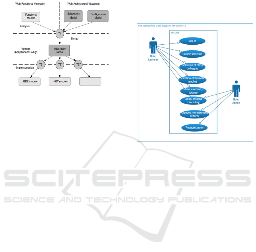
Figure 1: Web OOAD Development Process 0.
The advantage of the objects is that they are
hidden from outside, so they cannot depend on it and
there is no need to change when these objects are
changed. In addition, object-oriented fragmentation is
closer to the problem domain, because it directly
represents the actual sets with their structure and
behavior. The primitives of the abstractions, that are
built to be reused, have great potential to be reusable
so as the union between similar objects can be done
in the software libraries and then solutions can be
reused many times. Finally, the OO has the advantage
of continuity at time of the overall analysis,
implementation design, and continual representation
of the elements.
For that purpose and considering the afore-
mentioned OOAD techniques, the selected tools are
suitable for defining the functionalities that have to
satisfy system’s requirements in order to create the
best model for the problem. User stories, use case
descriptions and scenarios and use case diagrams are
used to describe the system functionality and gain the
functional model with dynamic behavioral
components (Tutorialspoint, 2019).
4 FUNCTIONAL MODEL OF IS
FOR IT EDUCATION
COMPANY
The functional model has to provide scenarios that
have to emerge from users, as an external view of the
IS. Combined with the use case diagrams, they can
provide useful information for business requirements
and specific users’ demands and interactions. The use
case diagrams are backed up by use case scenarios or
user stories and closely define the functional aspects
and IS’s dynamic behavior. The conceptual use case
diagrams are created after the first joint application
design (JAD) session with company users and
developers, as shown in Fig. 2.
Figure 2: Conceptual level of use-case diagram for IS for
company for IT education.
The company for IT education deals with
problems for the organization and delivers lectures in
several elementary, secondary and higher education
courses about Computer Science (Programming
Languages) and Mathematics. According to the
demands of the company for IT education, they
expected that the developed software should be a web
application accessible only to the employees of the
company for IT education. In this way, all activities
and tasks for each of the employees within the
educational center can be coordinated and monitored
with opportunities for the employees to receive
necessary information related to their activities,
starting from the part of providing conditions for IT
education. It is envisaged that the administrator of the
web application can monitor the overall work of all
lecturers and can make a reorganization of the
resources of the IT company. The lecturers would be
informed on time by using the web application about
the duties that they are referred to on daily, weekly or
monthly basis, to schedule and cancel classes and
other duties and to follow teaching obligations
according to the scheduled plan. The pupils cannot
use the system at this moment.
In the JAD session, users define the requirements
- the needs of the IT Company for successful
management. First, we define the system roles. In the
first development stage, the roles are limited to
lecturers and super-beneficiaries - an administrator
ICEIS 2019 - 21st International Conference on Enterprise Information Systems
368
(or IT company manager) and neglecting students,
parents and other stakeholders of the IT company.
Therefore, we create user scenarios for both roles:
lecturer and administrator. They have enriched with
detailed descriptions of all possible actions that the
system can undertake.
In the next stage, we define use case diagram on a
conceptual and then in logical level and according to
the users' views presented in the JAD session and user
stories about what activities have to be provided for
the two defined roles. Six detailed use case scenarios
for the first role (lecturer) and three for the second
role (administrator) are defined. Each of these
scenarios is split into a “child” diagrams for each use
case scenario, and then for each of them, adequate
activity diagram is created.
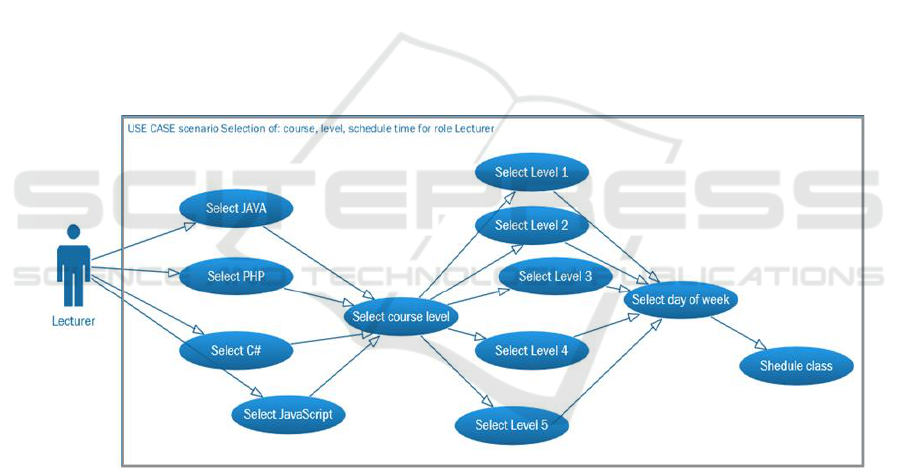
Fig. 3 and Fig. 4 show use case diagrams for the
ability of choosing a course, level of course and term
by the lecturer. As a requirement, the administrator
role has to create all these courses, levels of courses
and possible terms in order to enable the role of the
lecturer to have apossibility to make a choice from
them and to schedule classes by hours. Only after
creating this schedule, the students or pupils as
listeners can be added to the class. For each activity,
detailed use case diagram and activity diagram are
also created.
As additional option to the selection of courses
and course level, the lecturer can choose a new
education from the previously defined levels by the
administrator. By this concept, it is possible to create
flexibly possible courses, levels, terms and lecturing
classrooms. By using the concept of flexibility,
administrator has wide possibilities to create different
levels of data, different types of schools for each
level, according to the current requirements and the
levels at which students are enrolled. The
requirements for courses determine the number of
active groups and enable the planning of future
courses upon request. For all these combinations,
administrator has the capability to retrieve reports that
are flexible and to allow easily group resizing, as
shown in Fig. 5.
Figure 3: Use case diagram for the role Lecturer: course, level, time and location selection.
A Functional Model of Information System for IT Education Company
369
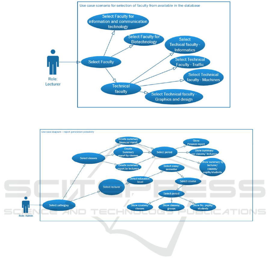
Figure 4: Use case diagram for the role Lecturer - selection of the faculty.
Figure 5: Use case diagram for the role Administrator and possibility to get reports.
5 PROPOSED FUNCTIONAL
MODEL OF IS FOR IT
EDUCATION COMPANY
The use case diagrams created for each user scenarios
lead to creating activity diagram. Activity diagrams
are developed interactively and incrementally in
sequence considering created use case diagrams.
Behavioral state machine diagrams are also created
for all complex entities representing the
transformations of each entity from one state to
another according to events that trigger their
transformations. Then, the class diagrams are defined
and created and they show the static view or the
system structure. The classes and class diagrams as
well as the object diagrams are created to move from
logical toward physical model of the developed
system.
Then, a high-level of logical model is considered,
and it has to present a logical data flow diagram
(DFD) as a part of the functional model. The diagram
supports generalization of the basic functions for the
FMIS4CITE. From all use cases and user’s scenarios,
the most basic functions are extracted and are
provided for both types of system’s users and from
them, as a result, the functional model for IS for IT
education is created. The proposed model is shown
for the two mentioned roles in Fig. 6 and Fig. 7 (users
and administrator, respectively). Particular activity
diagram arises for each detailed activity in order to
refine the user’s design requirements before creating
a physical model at a lower abstraction level. This is
very important for the design phase as well as for the
model validation. The model is suitable for similar
problem solving, taking into consideration dynamic
users’ specific requirements.
ICEIS 2019 - 21st International Conference on Enterprise Information Systems
370
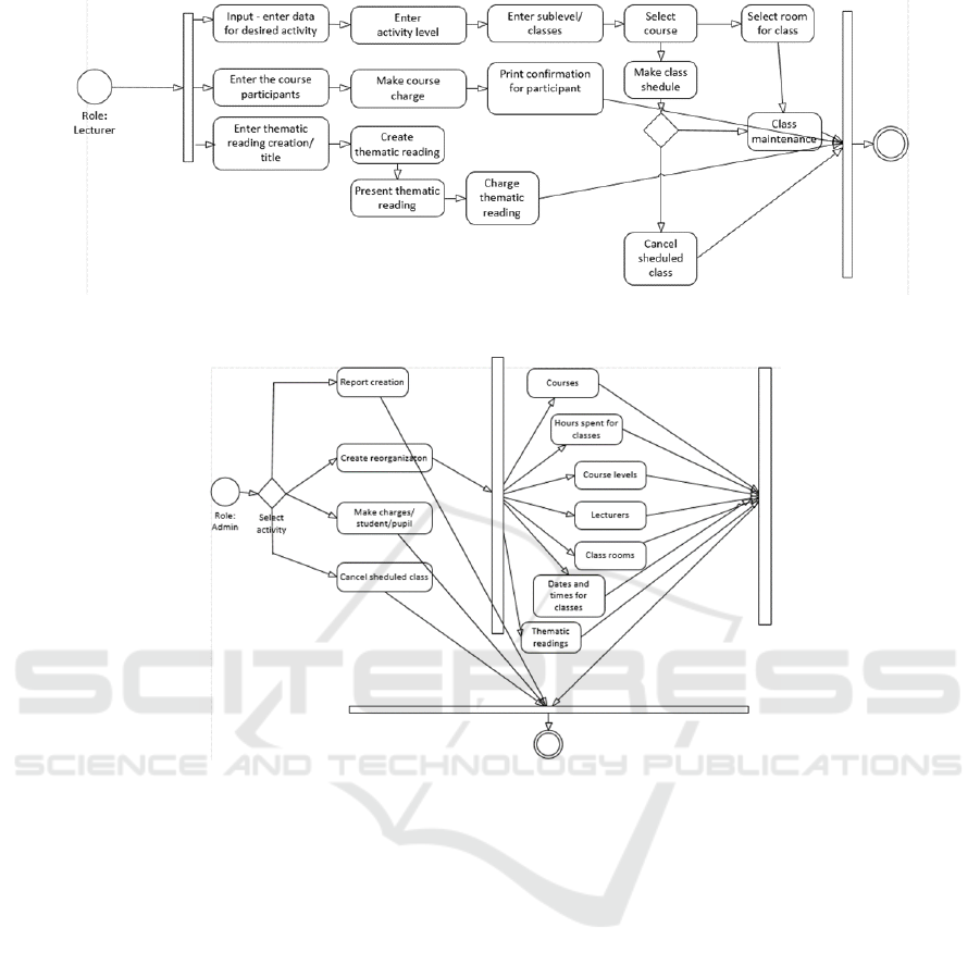
Figure 6: Proposed FMIS4CITE with activity diagram for the user’s role Lecturer.
Figure 7: Proposed FMIS4CITE with activity diagram for the role Administrator.
6 CONCLUSION
Functional modelling using OOAD is a powerful tool
for detecting business processes’ requirements that
has to be designed through the design phase. This is
the first, starting stage in the ISs modelling. The tools
available for OOAD are capable to replace traditional
DFD of system analysis and design with use case
diagrams and activity diagrams as well as activity
diagrams that highlight the external behavior of the
system. The paper focuses on functional modelling
using user scenarios and use case diagrams for
information systems for IT education Company
management, following its specific requirements. The
implementation of this IS needs to use an agile
development approach for refining the need diagrams
in order to satisfy users’ demands and create the best
human-computer interfaces.
Based on the user scenarios, a model of IS for
company for IT education is created for both
envisaged roles in the system with use case and
activity diagrams. The model describes the functional
and behavioral view of the system. The next activities
for the project will be refining the created class
diagrams, CRC and sequential diagrams and
improvement of the model in order to satisfy wider
students and pupils’ demands for information.
Adding system functionalities should be flexible
since the system is designed to be dynamic because
the administrator can change its functionality. As a
further work, semantic model for the web application
has to be created with predefined ontology. The
model validation has to be done in a real regional
company for IT education in our country as a web
based solution, providing informaton for IT company
management.
The proposed model creation can be used as a case
study scenario or example of creating specific
information systems for companies that have some
dynamic demands for software development. It
means that these steps can be used as method that
A Functional Model of Information System for IT Education Company
371

needs to go through three phases: first JAD approach
for detecting users’ requirements; second functional
modeling with defining the system’s roles and
functionalities, transforming functional requirements
into use case scenarios and descriptions and use case
diagrams. The third phase is creating of activity
diagrams for defined roles in order to create a clear
view of IS’s functionality for designers.
Many other approaches are also suitable for
complex system development and new big data era,
and give exciting results, taking place in university
curriculum (Kaloyanova, 2014, 2018). For successful
business model, creation of functional model and
transforming into dynamic and structural model is
important, especially when some dynamic web based
systems are planned to be designed.
REFERENCES
Friedenthal, S., Moore, A. and Steiner, R., 2008, June. Omg
systems modeling language (omg sysml™) tutorial. In
INCOSE international symposium (Vol. 18, No. 1, pp.
1731-1862).
Hoffmann, H.P., 2005. UML 2.0-Based Systems
Engineering Using a Model-Driven Development
Approach. CrossTalk The Journal of Defense Software
Engineering, pp.1-18.
Hoffmann, H.P., 2008. SysML-based systems engineering
using a model-driven development approach. White
Paper, Telelogic.
Hart, L.E., 2015, July. Introduction to model-based system
engineering (MBSE) and SysML. In Delaware Valley
INCOSE Chapter Meeting, Ramblewood Country Club,
Mount Laurel, New Jersey.
Ripon, S., Azad, K., Hossain, S.J. and Hassan, M., 2012,
September. Modeling and analysis of product-line
variants. In Proceedings of the 16th International
Software Product Line Conference-Volume 2 (pp. 26-
31). ACM.
Balazs P., Horváth A., 2010, The System Modeling
Language (SysML) and the SYSMOD modeling
approach, Budapest University of technologies and
economics, Lecture 10.
Weilkiens, T., 2011. Systems engineering with
SysML/UML: modeling, analysis, design. Elsevier.
Pressman R.S., 2010, Software Engineering: A
Practitioner's Approach, RS Pressman & Associates.
Inc., McGraw-Hill, 7
th
edition.
Hoffmann, H.P., 2011. Model-based systems engineering
with rational rhapsody and rational harmony for
systems engineering. Deskbook Release, 3(2).
Dennis, A., Wixom, B.H. and Tegarden, D., 2015. Systems
analysis and design: An object-oriented approach with
UML. John wiley & sons.
Booch, G., 2005. The unified modeling language user
guide. Pearson Education India.
Schwinger W. and Koch N., 2006, Modeling web
applications, Web Eng., pp. 39–64.
Larman, C., 2012. Applying UML and patterns: an
introduction to object oriented analysis and design and
interative development. Pearson Education India.
Tutorialspoint, 2019,
https://www.tutorialspoint.com/object_oriented_analys
is_design/ooad_functional_modeling.htm.
Maguire S., 2017, Business modelling Techniques, 2017,
Sparx Systems.
Van Den Berg, K., Dekkers, T. and Oudshoorn, R., 2005,
March. Functional size measurement applied to UML-
based user requirements. In Proc. Software
Measurement European Forum (SMEF 2005) (pp. 69-
80).
Doran, T., Systems and Software Life Cycle Process
Standards: Foundation for Integrated Systems and
Software Engineering.
Dingsøyr, T., Nerur, S., Balijepally, V. and Moe, N.B.,
2012. A decade of agile methodologies: Towards
explaining agile software development.
Kaloyanova, K., 2014. An Implementation of the Project
Approach in Teaching Information Systems Courses. In
INTED2014 Proceedings (pp. 7090-7096). IATED.
Kaloyanova, K., 2018, An educational environment for
studying traditional and big data approaches. In:
INTED2018 Proceedings (pp. 4270–4274).
ICEIS 2019 - 21st International Conference on Enterprise Information Systems
372
