
Software-in-the-Loop-simulation of a District Heating System as Test
Environment for a Sophisticated Operating Software
Ophelia Frotscher
1
, Thomas Oppelt
1
, Thorsten Urbaneck
1
, Sebastian Otto
2
, Ingrid Heinrich
2
,
Andreas Schmidt
2
, Thomas Göschel
3
,
Ulf Uhlig
3
and Holger Frey
3
1
Chemnitz University of Technology, Faculty of Mechanical Engineering, Professorship Applied Thermodynamics,
09107 Chemnitz, Germany
2
Ingenieurbüro Last- und Energiemanagement LEM Software, Nordplatz 6, 04105 Leipzig, Germany
3
inetz GmbH, Augustusburger Straße 1, 09111 Chemnitz, Germany
Keywords: Software-in-the-Loop, District Heating, Renewable Energy, Operation, Simulation, Optimisation.
Abstract: With the expansion of renewable energies, district heating (DH) systems are becoming increasingly complex.
Various heat sources like solar thermal plants and combined heat and power (CHP) plants are integrated in
parallel, in addition thermal energy storages (TES) are often used to balance load and heat generation.
Sophisticated software solutions are required to optimise the plant operation. Based on deterministic physical
models and artificial neural networks, the software Heating Network Navigator (HN-Navi) is being developed
to optimise the operation of such systems. Since tests in the real system are not possible for reasons of supply
security, the HN-Navi is first tested in a software-in-the-loop (SiL) environment. TRNSYS (version 18) is
used as simulation software to create a complex reference model (CRM) as basis for the SiL environment.
The complexity of such real energy systems can lead to potentially high computing costs when it comes to
simulating or optimising their operation as realistically and accurately as possible. For this reason, both
software tools, i.e. HN-Navi and CRM, will be developed and tested with regard to the Brühl solar DH system
in Chemnitz (Germany), whereby the finished software will also be used for other heat supply systems.
TRNSYS offers the possibility to develop own models for all system components, with which a proper
reproduction of the real system can be achieved. Within the scope of the project, practical tests and extensive
quantitative software comparisons with the real system will also be carried out. The article reports on the
development of this SiL environment and its practical feasibility.
1 INTRODUCTION
More and more district heating systems in Europe
combine different heat sources like solar thermal
plants and combined heat and power (CHP) plants
(solar district heating, 2019). In most cases a thermal
energy storage (TES) is applied for balancing load
and heat generation, e. g. the solar district heating
(DH) systems in the Brühl quarter in Chemnitz
(Urbaneck et al., 2015; Urbeneck et al., 2017,
Shrestha et al. 2017; Urbaneck et al. 2017; Urbaneck
et al. 2017). The different components within such
systems lead to complex structures with mutual
influences. This means that a quantitatively optimal
operation can only be guaranteed through the use of
sophisticated software solutions.
For this reason, numerous projects are now
dealing with the optimization of energy supply
systems. Widely used approaches include the use of
prediction models to estimate the availability of
renewable energies and energy demand (Kuboth et
al., 2019) and improved simulation models to
predictively describe the plant behaviour of such
systems (Schweiger et al. 2018).
The approach of this project, which has been
running since July 2017, is the optimization of the
supply facilities. One of the advantages is the direct
contact with the network operator without troubling
the end customers and the optimization of the control
of all system components. The developed software
system is named Heating Network Navigator (HN-
Navi) (Oppelt et al., 2018; Oppelt et al., 2018) and is
intended to help heating network operators to achieve
an optimal system operation despite difficult
boundary conditions (integration of fluctuating
renewable energy sources, varying electricity prices,
etc.) and complex technical demands.
Frotscher, O., Oppelt, T., Urbaneck, T., Otto, S., Heinrich, I., Schmidt, A., Göschel, T., Uhlig, U. and Frey, H.
Software-in-the-Loop-simulation of a District Heating System as Test Environment for a Sophisticated Operating Software.
DOI: 10.5220/0007809602230230
In Proceedings of the 9th International Conference on Simulation and Modeling Methodologies, Technologies and Applications (SIMULTECH 2019), pages 223-230
ISBN: 978-989-758-381-0
Copyright
c
2019 by SCITEPRESS – Science and Technology Publications, Lda. All rights reserved
223
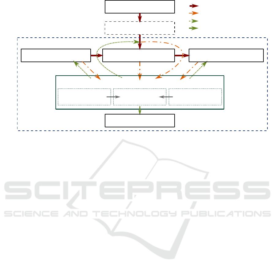
Figure 1: Integration of the Heating Network Navigator into a quarter heating system.
Figure 1 schematically shows the planned
application of the HN-Navi to the particular town
quarter DH system (in this case: Brühl quarter,
Chemnitz, Germany) (Urbaneck et al. 2017).
Considering the specific requirements:
optimal operation of TES,
best possible utilisation of solar irradiance,
minimize competition of solar heat and CHP,
minimize network supply temperature,
maximize temperature difference between supply
and return line of the network.
The HN-Navi generates recommendation for optimal
operation from stored (Past) and currently received
(Present) measurement data as well as load and
demand forecasts (Future). This advice for a defined
time horizon is then sent back to the process control
system in order to be considered. Additionally, the
HN-Navi continuously compares operational data
from past and present in order to detect errors in the
system (Error identification).
The project consists of three stages of
development:
1. Software developments: Development and
abstraction of simulation and prognosis models,
2. Software tests: Conducting the tests in a
Software-in-the-loop (SiL) environment,
3. Software application: Performing the practice
tests in the Brühl solar DH system at Chemnitz
(Brühl system) supported by the network
operator inetz.
The first development stage has already (status:
May 2019) been completed, so the first SiL-tests of
the optimization software have already been started.
Section 2 describe the developing of a complex
reference model (CRM) to the real system and the
HN-Navi while section 3 explains the creation of the
Software-in-the-Loop (SiL) environment. Section 4
gives an outlook on the following project steps.
2 SOFTWARE DEVELOPMENT
As stated above the aim of this to project is to use the
HN-Navi in the real Brühl system. Since tests in the
real system are not possible for reasons of supply
security, the HN-Navi is first tested in a software-in-
the-loop (SiL) environment. TRNSYS (version 18) is
used as simulation software to create a CRM as basis
for the SiL environment.
In response to the requirements, the development
is done in the following steps:
1. Analysis of the real Brühl system with a heat
transfer station (HTST), two solar thermal fields,
a TES and a low temperature network,
2. Development of accurate models of the system
components for the CRM.
3. Development of the forecast models and
abstraction of the system component models for
the HN-Navi.
2.1 Analysis of the Brühl System
The main components of the plant are two solar
thermal collector fields, a two-zone-storage TES and
a HTST which connects the low-temperature network
Heat flow
Measured data
Advice t process control systemo
Collector field flow rate Network supply temperature
Auxilliary heating request
Heating Network Navigator
Error identification
Thermal energy storage Quarter heating networkSolar thermal plant
Primary DH network
CHP plant
Quarter heating supply system
Past
(historical database)
Present
(measeured data)
Future
(ANN, system models)
Message t network operatoro
SIMULTECH 2019 - 9th International Conference on Simulation and Modeling Methodologies, Technologies and Applications
224
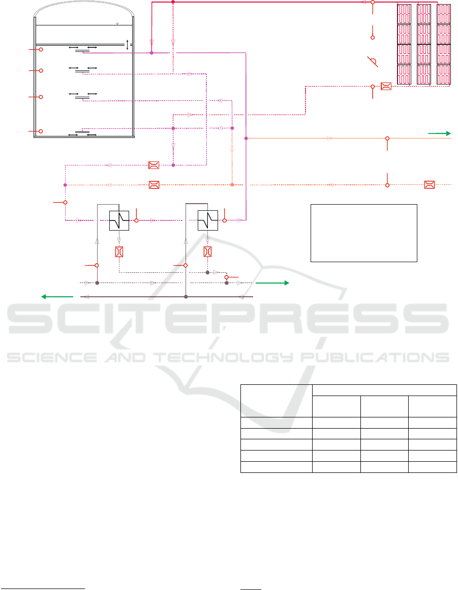
Figure 2: Simplified structure of the heat transfer substation (supply center), solar collector fields and two-zone storage of the
solar DH system Brühl (without pumps) and schematic representation of the most important measured system values required
by the Heating Network Navigator.
to the primary DH network. The supplied city quarter
(Brühl Chemnitz (Shrestha et al., 2018) includes
mainly apartment buildings with more than 1,300
residential units, a school and the university library.
Figure 2 schematically shows the hydraulic
design of the Brühl system. The TES can be charged
either via the HTST, the solar thermal collector fields
or the return flow from the supply system. Similarly,
the quarter can be supplied via the solar collector
fields, the TES, the HTST or in combination thereof.
The possible operating modes are listed in Table 1. A
more detailed description can be found by Shrestha
et. al. which demonstrates the entire complexity of
the system (Shrestha et al., 2018).
In addition to the various operating modes, each
system has its own specific requirements, which has
to be taken into account in the software tools.
The most important points concerning the solar DH
system Brühl are:
Network and HTST:
Low-temperature network with supply
temperatures of about 70 °C.
Hydraulic decoupling of the primary DH network
from the Brühl system due to pressure and
Table 1: Operating modes of the supply center for
supplying the Brühl quarter.
Operating
modes of the
supply center
Heat source
HTST
TES
Collector
fields
A
Yes
B
Yes
C
Yes
Yes
D
Yes
E
Yes
Yes
temperature differences in both systems.
Consisting of a preheating (prh) and a
postheating (poh) stage each with two heat
exchanger groups (HX).
Preheating stage using the return flow from the
primary DH network Chemnitz.
Postheating stage using the supply flow from the
primary DH network Chemnitz (Differences
between DH systems in Table 2).
TES:
Two-zone TES storing with a maximum
operation temperature up to 108 °C.
q
u
a
r
t
e
r
B
r
ü
h
l
low-temperature network
s
o
l
a
r
t
h
e
r
m
a
l
c
o
l
l
e
c
t
o
r
f
i
e
l
d
s
l
e
v
e
l
1
l
e
v
e
l
2
l
e
v
e
l
3
l
e
v
e
l
4
HX prh1 - HX poh2 -
c
o
m
b
i
n
e
d
h
e
a
t
a
n
d
p
o
w
e
r
p
l
a
n
t
d
i
s
t
r
i
c
t
h
e
a
t
i
n
g
p
i
p
e
l
i
n
e
s
c
i
t
y
o
f
C
h
e
m
n
i
t
z
t
w
o
-
z
o
n
e
-
s
t
o
r
a
g
e
b
a
l
l
a
s
t
z
o
n
e
s
t
o
r
a
g
e
z
o
n
e
p
r
o
t
e
c
t
i
v
e
g
a
s
T
T
T
T
a
m
b
i
e
n
t
t
e
m
p
e
r
a
t
u
r
e
s
e
n
s
o
r
r
a
d
i
a
t
i
o
n
s
e
n
s
o
r
V
T
T
V
T
V
T T
T
V
V V
TT
T
... heat exchanger
... postheating
... preheating
... temperature sensor
... flow rate sensor
HX
poh
prh
T
V
T
return line
supply line
Software-in-the-Loop-simulation of a District Heating System as Test Environment for a Sophisticated Operating Software
225

Charging and discharging with radial diffusors in
levels 1…4 (Figure 2), depending on operation
mode.
Table 2: Maximum pressure and temperature in the supply
line of the primary DH network and the low temperature
network (Brühl system).
Supply line
Primary DH
network
Solar DH
system
Brühl
Pressure [bar]
17
5,5
Temperature [°C]
140
85
Collector fields:
Water is used as heat transfer medium.
No heat exchangers between solar circuit and
supply system are required.
Frost protection is provided by an active hot
water flow, obtained from the TES or the return
flow from the Brühl quarter (not shown in Figure
2).
2.2 The Complex Reference Model
TRNSYS (version 18) is a software environment to
simulate a variety of energy systems (TRNSYS,
2017). TRNSYS is a Fortran 95 based and well-
validated software package to consider models of
many components of energy systems. It is also
possible to the end user to implement own models.
The user-specific components can be inserted
modularly into the simulation, which facilitates the
adaptation to extensions and to future systems. In
addition, TRNSYS offers various interfaces for data
exchange (import and export) as well as for other
programs (e.g. MATLAB). For these reasons the
CRM developed here is based on TRNSYS.
To map the DH system, the most important step is the
selection of suitable components in TRNSYS which
are called Types. The various available Types were
compared to the real system on the basis of their
reproduction quality. For example the model of the
solar collector should match the efficiency curve, the
matched flow control and the collector connection,
while taking the multi-node model, the incident angle
modifier and the heat capacity of the collector into
account. Table 3 shows available Types for the model
of the flat plate collector.
Due to the high database (minute values since
May 2017) from the monitoring of the real plant, the
simulation results can be verified directly to the
measured values (Figure 2). In the example of the
solar collector the Type 539 TESS library is sufficient
accurate and is used in the simulation (TRNSYS,
2017).
For other components (e.g. TES, HTST) no
adequate models are available in TRNSYS. These
had to be created within the scope of this project.
Another important aspect in simulating complex DH
systems in TRNSYS is the realistic control of the
interaction of the individual model components. A
separate Type (Control Unit) was developed for this
purpose, see Figure 3.
This Type establishes the link between quarter
network, HTST, collector fields and TES. It
determines the mass flows in the four diffuser levels
in the TES as well as the temperatures of the mass
flows. The Type also determines the correct diffusor
level for the mass flows from the network and from
the collector planes. Furthermore, it determines the
operating condition of the storage tank and the HTST
and calculates the heat flows required for evaluation.
The boundary conditions of the simulation (weather
data and heat demand) are also considered by the
Control Unit Type.
Table 3: Evaluation of the TRNSYS models on the basis of the most important parameters, e.g. model for solar collectors.
Type
Efficiency
curve
Matched
flow
control
Collector
inter-
connection
Mutli node
model
Incident
angle
modifier
Heat
capacity
001: Flat-plate
collector
Yes
Yes
Yes
301: Matched
flow collector
model
Yes
Yes
Yes
Yes
539: Flat plate
collector with
capacitance
effects
Yes
Yes
Yes
Yes
Yes
Yes
832: Dynamic
collector model
Yes
Yes
Yes
Yes
SIMULTECH 2019 - 9th International Conference on Simulation and Modeling Methodologies, Technologies and Applications
226
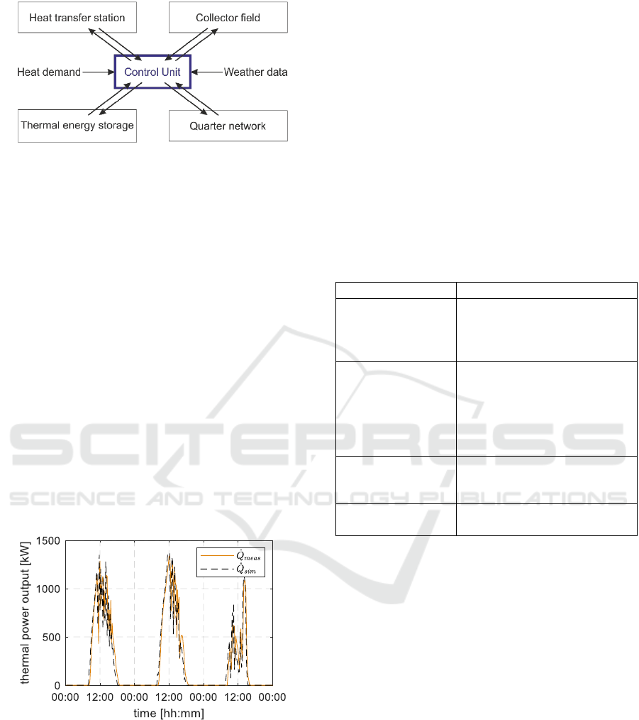
Figure 3: Schematic representation of the Brühl system in
as TM in TRNSYS with the central Type to connect and
control the individual model components.
The main part is to determine the respective operating
modes based on iteration methods. Thus the type
represents the core of the CRM (Figure 3).
Figure 4 compares the actual output of the
collector arrays with that calculated by the CRM for
three days. The correlation coefficient amounts 0.93
and an average deviation of -3.14 % is calculated for
this period. Deviation between measurement and
CRM for the whole year 2018 is about +4.4 %, which
demonstrates that the CRM is sufficient accruable.
By this approach the models of all system
components are developed and tested. Analogously,
all other model components were tested and
positively validated.
Using an intel®Core
TM
i7, one year in calculation
steps of three minutes can be simulated with the CRM
in less than 4.5 minutes. This allows various tests
such as parameter variation, algorithm verification
and error detection.
Figure 4: Comparison of the measured (
, orange) and
simulated (
, dashed black) thermal power of the
collector fields. From 19. to 21. July 2018. The time
resolution is 15 min.
2.3 The Heating Network Navigator
The HN-Navi is intended to replace the control and
must therefore specify the optimum volume flows and
temperatures of the individual components (Figure 2)
for a defined time step. Therefore the HN-Navi
contains weather (radiation and temperature),
electricity price and load (supply temperature and
flow rate) forecasts based on artificial neural
networks. For each optimization run, are also the
current state values from the CRM (later measured
values from the real system) are used for the initial
values On the basis of the forecasts and the initial
values, the determined numerical optimization is
carried out in the main part of the HN-Navi. Like the
CRM, the main part contains models for the
respective system components.
Table 4: Classification of the parameters into “absolutely
necessary”, “necessary”, “expense-dependent” and
“unnecessary”, e.g. solar thermal plants.
Criteria
Parameter
absolutely
necessary
- field size
- collector efficiency
- collector orientation
- collector tilt
necessary
- field shadowing
- angular influence
- sky model
- heat loss at frost
protection
- soiling
expense-
dependent
- heat capacity (collector)
- separate consideration
south/ north field
unnecessary
- heat loss field
connection
In order to keep the numerical effort low and the
solvability within the framework of an at most
quadratic optimization problem, the model
components are abstracted in comparison to the
CRM. For the abstraction of the individual elements
an investigation with variation of all parameters and
correlations was conducted, using the models from
the SiL environment. The classification is based on
the resulting deviation of important parameters (yield,
heat quantities, operating hours, etc.) from the real
system in four categories:
“absolutely necessary”: Parameter or correlation
should be considered in the same way as in the
SiL environment.
“necessary”: Parameter or correlation should be
considered, but can be simplified, e.g. in a black
box model. Abstraction must be justified.
“expense-dependent”: Depending on the
computing effort to be taken into account or not.
“unnecessary”: No consideration required.
Software-in-the-Loop-simulation of a District Heating System as Test Environment for a Sophisticated Operating Software
227
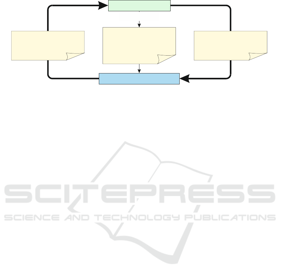
Figure 5: Test procedure for the SiL Simulation; for details of the Heating Network Navigator see Figure 1.
New models were created for each system
component, which was simplified on the basis of the
criteria.
New models were created for each system
component, which was simplified on the basis of the
criteria.
Table 4 shows the classification of the
parameters using the example of solar thermal
collector arrays. New models were created for each
system component, which was simplified on the basis
of the criteria.
The HN-Navi optimizes the entire system
considering all underlying physics. Various
optimisation strategies can be considered (minimum
operating costs
, minimum CO
2
emission
).
The time resolution is arbitrary. The software
generates optimal control suggestions (mass flows ,
temperatures ) for all models and elements.
3 SOFTWARE IN THE LOOP
To test the HN-Navi, communication between it and
the CRM is necessary. A separate type was created
for this process. It checks every 10 seconds a defined
exchange folder for the existing file containing the
next schedule. A maximum number of queries can be
specified to prevent hanging in the loop and must be
adjusted to the optimization time.
The procedure is shown in Figure 5.
Before the first optimization time step, the CRM
provides the optimization parameters (start time,
simulation time step, optimization time step and end
time) as well as the current system data (temperatures,
mass flows, etc.). The HN-Navi starts the
optimization, meanwhile the CRM is in a sleep mode
until the necessary values for the system operation
(temperatures, mass flows) are returned.
The state values of the simulation are written to
the same exchange folder parallel to the simulation.
This allows the optimizer to perform a continual
comparison with its forecasts, just as it would later do
in the real system.
The development of the SiL environment is
already finished (status: May 2019) and first tests are
still ongoing. Quantitative results will be presented in
future works.
4 OUTLOOK
The next steps are an iterative process, in which the
HN-Navi will be improved. The test purposes are the
solution of different operating scenarios, the
examination of the solutions and the increase of the
performance.
Therefore, there will be four stages of testing:
1. Forecasting models:
Comparing the forecasted heat demand and
weather data in their daily forecast to the real
data;
2. System control:
Checking the control mechanisms (appropriate
specifications and control parameters),
Solvability of different operating scenarios;
3. Optimal operation:
Software training to find the optimal solution,
while considering the lowest costs or lowest
CO
2
emission;
4. Error detection:
Implementation from error detection algorithms
to find acute and creeping errors and secure the
system operation.
After this last step the software will be tested in the
real Brühl System. As soon as the tests have been
completed to the satisfaction of all project partners,
the software will be brought to market by LEM
Complex Reference Model
Heating Network Navigator
Optimization parameters:
- start time
- simulation time step
- optimization time step
- end time
Optimization time table:
- temperatures,
- mass flows,
- etc.
Current system values:
- temperatures,
- mass flows,
- etc.
bevor first
optimization time step
SIMULTECH 2019 - 9th International Conference on Simulation and Modeling Methodologies, Technologies and Applications
228

GmbH. The experiences of the project shall be used
to adapt the software to other district heating supply
systems.
5 CONCLUSIONS
SiL simulations are an important instrument to
develop and test software solutions. The development
of simulation and optimization tools for complex
systems is necessary because these systems can no
longer be calculated manually. In this case TRNSYS
is used to simulate a complex district heating system
with solar thermal plants and a short-term thermal
energy storage (Brühl system).
To warranty the supply safety, it is not possible to
test the software solution Heating Network Navigator
in the real system. This is the reason to combine
simulation and optimization to test the software in
advance. The example shows that TRNSYS as
modular and flexible simulation software is able to
fulfil such complex requests. Especially since own
models can be easily created and implemented.
In the context of this article, the creation of the
CRM and the Heating Network Navigator as well as
the linking of the two in the Software-in-the-Loop test
were presented. In the next step, the software tests can
begin.
ACKNOWLEDGEMENTS
The project underlying this paper is funded by the
German Federal Ministry for Economic Affairs and
Energy under the codes ZF4389101ST7/
ZF4147602ST6 following a decision by the German
parliament. Special thanks also go to the AiF Projekt
GmbH for supporting the project. The sole
responsibility for the content of the report lies with
the authors.
NOMENCLATURE
ANN
artificial neural network
C
charging
CHP
combined heat and power
CRM
complex reference model
DC
discharging
FP
frost protection
HM
heat maintenance
HTST
heat transfer station
HX
heat exchanger
in
inlet
out
outlet
prh
preheating
prim
primary
poh
postheating
RL
return line
sec
secondary
SiL
software in the loop
SL
supply line
TES
thermal energy storage
[€]
operating cost
[kg/s]
mass flow
[kg]
mass of CO
2
[°C]
temperature
[m
3
/s]
flow rate
REFERENCES
SDH - solar district heating: Ranking List of European
Large Scale Solar Heating Plants. https://www.solar-
district-heating.eu/en/plant-database/. checked:
14.05.19
Urbaneck, T.; Oppelt, T.; Platzer, B.; Frey, H.; Uhlig, U.;
Göschel, T.; Zimmermann, D.; Rabe, D.: Solar District
Heating in East Germany – Transformation in a
Cogeneration Dominated City. Energy Procedia, Vol.
70 (2015) pp. 587–594. DOI:
10.1016/j.egypro.2015.02.090
Urbaneck, T.; Oppelt, T.; Shrestha, N. Lal; Platzer, B.;
Göschel T.; Uhlig, U.; Frey, H.: Technische Umsetzung
der solaren Fernwärme Brühl. EuroHeat&Power,
VWEW Energieverlag 46. Jg. (2017) 11 pp. 20-23. –
ISSN 0949-166X
Shrestha, N. Lal; Urbaneck, T.; Oppelt, T.; Platzer, B.;
Göschel T.; Uhlig, U.; Frey, H.: Implementation of
large solar thermal system into district heating network
in Chemnitz (Germany) In: International Solar Energy
Society (Hrsg.): ISES Solar World Conference 2017
and the IEA SHC Solar Heating and Cooling. Freiburg,
2018, pp. 322-332. - ISBN 978-3-9814659-7-6
DOI:10.18086/swc.2017.06.08
Urbaneck, T.; Oppelt, T.; Shrestha, N. Lal; Platzer, B.;
Göschel T.; Uhlig, U.; Frey, H.: Technische Umsetzung
der solaren Fernwärme Brühl. EuroHeat&Power,
VWEW Energieverlag 46. Jg. (2017) 11 pp. 20-23. –
ISSN 0949-166X
Urbaneck, T.; Fürbaß, G.; Stillger, G.: Energetische
Stadtsanierung in Chemnitz – auf dem Weg zur grünen
Fernwärme. In: Klimaschutz & erneuerbare Wärme –
Beispiele, Aktivitäten und Potenziale für die
kommunale Wärmewende. Köln: Deutsches Institut für
Urbanistik (Hrsg.) p. 54-61 2017. – ISBN 978-3-88118-
583-7
Kuboth, S.; Heberle, F.; König-Haagen, A.; Brüggemann,
D.: Economic model predictive control of combined
Software-in-the-Loop-simulation of a District Heating System as Test Environment for a Sophisticated Operating Software
229

thermal and electric residential building energy systems.
Applied Energy, Vol. 240 (2019) p. 372-385,
www.elsevier.com/locate/apenergy
Schweiger, G.; Gomes, C.; Hafner, I.; Engel, G.; Nouidui,
T. S.; Popper, N.: Co-Simulation: Laveraging the
Potential of Urban Energy System Simulation.
EuroHeat&Power English Edition VWEW
Energieverlag, Vol. 15, I-II/2018, pp. 13 - 16
Oppelt, T.; Urbaneck, T.; Platzer, B.; Otto, S.; Heinrich, I.;
Schmidt, A.; Göschel T.; Uhlig, U.: Wärmenetz-
Navigator optimiert den Betrieb von Wärmenetzen.
EuroHeat&Power, VWEW Energieverlag 47. Jg.
(2018) 6 pp. 42-45. – ISSN 0949-166X
Oppelt, T.; Urbaneck, T.; Otto, S.; Heinrich, I.; Schmidt,
A.; Göschel, T.; Uhlig, U.; Frey, H.: Development of a
software system for optimal operation of heating
networks with central solar plant. In: EuroSun 2018:
12th International Conference on Solar Energy and
Buildings. Rapperswil (Schweiz), 2018. – ISBN 978-3
-9820408-0-6 DOI:
https://doi.org/10.18086/eurosun2018.05.05
Shrestha, N. Lal; Urbaneck, T.; Oppelt, T.; Göschel T.;
Uhlig, U.; Frey, H.: Special Storage Management and
System Concept - Large-scale Solar District Heating
System Operates as Expected. EuroHeat&Power,
English Edition VWEW Energieverlag Vol. 15 (2018)
3 pp. 19-27. – ISSN 1613-0200
Solar Energy Laboratory, University of Wisconsin-
Madison: TRNSYS 18 – a Transient System Simulation
program, 2017, http://www.trnsys.com/
SIMULTECH 2019 - 9th International Conference on Simulation and Modeling Methodologies, Technologies and Applications
230
