
System for Controlling a Wind Turbine
Corneliu Buzduga
Stefan cel Mare University, 13 University, Suceava, Romania
Keywords: Wind Turbine, Power Generator, Positioning System, Transmission System, Sensors.
Abstract: This paper presents the improving operating principle of a wind turbine actually achieving an optimum control
of the rotation speed. This control consists in limiting the speed of rotation to a permissible maximum value
based on the peripheral speed determined by tests of resistance of the materials from which the blades are
made. Constructively, the whole mechanism is built from a set of interconnected functional blocks such as:
the positioning system, the shaft-hub-shaft assembly, the transmission system, the blade step change system
and, last but not least, the generator.
1 INTRODUCTION
Since the weather conditions are not constant, with
slow or sudden variations in both direction and
intensity of the air currents, the optimum operating
point of the generator suffers permanent changes, the
generator must continually adapt to environmental
conditions (U.S. Energy Information Administration,
2013). Optimal position detection and adaptation go
to a smart microprocessor-based system. This,
according to predefined instructions, will have to
interpret the data from various sensors and perform
wind turbine operation corrections so that a maximum
output is reported consistently at the given wind
speed and safe operation of the whole assembly. The
electricity produced by this wind turbine is stored in
the batteries as a reserve or consumed directly (World
Energy Council, 2010).
In operation, an important aspect is the height
regime at which the turbine will be installed, known
as the dynamics of the air currents differ at altitude,
thus a height between 10 ÷ 15 meters of the tower is
an economically suitable choice and aesthetically,
framing the entire system in the landscape, but also
places the turbine in an area of turbulent air flows due
to both neighbouring constructions and tree
vegetation. Another determinant factor that
influences the efficiency of the turbine is its location,
which often proves to be less favourable and,
compared to the airflow maps of its direction and
intensity, determines that the installation of a wind
turbine be considered less profitable (Wagner, 2017).
Electricity is directly proportional to both the
rotor speed of the generator and the mechanical
power of the propeller shaft. The two parameters are
dependent on each other in the sense that the
mechanical power at the shaft is determined by the
structural characteristics of the blades (dimensions
and aerodynamics) and the maximum speed of
rotation under safe conditions is determined by the
diameter of the turbine. In order to eliminate this
inconvenience, the solution addressed was the use of
an oversized turbine, thus ensuring at the same wind
speed a greater mechanical power on the turbine
shaft. With this solution we succeeded in changing
the operating point, the target being the production of
electricity at wind speeds starting at 3,5 ÷ 4 m/s, but
at the same time this solution radically changes the
dynamics of operation at high speeds, which,
although rare manifestation, the likelihood of
occurrence during violent storms jeopardizes the
integrity of the system. Under this consideration, in
addition to the production of electricity, which is the
main aspect to be pursued, the consideration should
also be given to the protection systems of the entire
device so that its operation can be safely carried out
regardless of the weather conditions to which it is
subjected (Jianbo and Qunyi Liu, 2017).
The protective systems must ensure continuous
adaptation of the turbine to environmental conditions,
and be able to react to all factors that can disrupt
proper operation. Although it is a more sophisticated
implementation method, the electronic control
solution brings several advantages such as continuous
adaptation according to a calculation algorithm,
Buzduga, C.
System for Controlling a Wind Turbine.
DOI: 10.5220/0007827502190225
In Proceedings of the 8th International Conference on Smart Cities and Green ICT Systems (SMARTGREENS 2019), pages 219-225
ISBN: 978-989-758-373-5
Copyright
c
2019 by SCITEPRESS – Science and Technology Publications, Lda. All rights reserved
219
remote control and monitoring of operating
parameters (Suaad, 2013)
2 SYSTEM SETUP
2.1 The System Components
a. THE ROTOR
The rotor or propeller consists of three movable
blades around the longitudinal axes assembled on a
supporting hub and represents the active element that
transforms the kinetic energy of the wind into
mechanical energy available on its own shaft, which
rotates when the air currents is present and the turbine
are aligned in their direction. The mobility of blades
around their own axis is useful and necessary at the
same time to change the angle of attack, known as
pitch, in this way controlling the speed of rotation
until it keeps the rotor at constant speed regardless of
the wind speed.
A particular case is the passing of the blades in a
flag step, in this way the propeller can be dynamically
broken as a further protection during storms.
Figure 1: The hub and the mechanical interconnection
system of the blades.
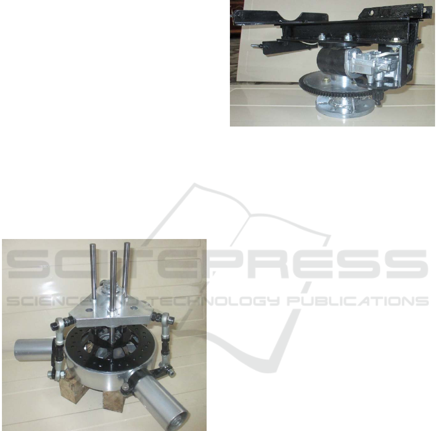
b. THE ORIENTATION SYSTEM
The orientation system is designed to position the
nacelle, making a 360 degree rotation around the axis
of the tower (vertically to the ground plane). The
positioning is carried out by a universal DC motor,
with a built-in speed reducer, controlled by the
microcontroller, which has as reference the position
of a wind direction sensor, called weathervane.
Depending on the weather conditions, the nacelle is
oriented with the rotor in the wind direction, over a
minimum operating threshold, always aiming at
correcting the position.
Figure 2: The orientation system, drive motor and chassis.
As the construction number has been reduced as
much as possible, the guidance system also has a
secondary supporting role, being the link between the
pillar and the support frame of all mechanical and
electrical components.
c. THE TRANSMISSION SYSTEM
The transmission system is designed to drive the
rotation movement taken from the main shaft and
deliver it to the generator. By comparison, the
behaviour of the transmission is similar to a gearbox
of a car, but operating in the sense of increasing the
rotation, with a continuous transmission ratio of 1: 1.4
to 1: 4.7, respectively the amplification follows a
straight slope between the intervals minimum and
maximum, there being no thresholds that can cause
vibrations in the pillar when switching gears.
The transmission ratio is changed electrically by
means of a universal DC motor controlled by the
microcontroller, which monitors the incoming and
outgoing speeds during operation of the system. In
order not to force the rotor and eventually premature
shutdown of the turbine, changing the ratio of the
transmission to the amplification direction will be
performed only after the propeller has reached a
minimum threshold of 400 rpm, at which point the
input shaft speed will remain at an approximate
threshold constant. If the wind speed decreases in
intensity and the turbine output decreases, the
transmission gradually returns to the minimum
threshold, with the condition that the propeller does
not fall below 400 rpm and the transmission has a
positive gain ratio.
d. THE POWER GENERATOR
The power generator that supplies the turbine is the
result of changing a synchronous motor in the sense
MoMa-GreenSys 2019 - Special Session on Modelling Practical Paradigms of Green Manufacturing Systems
220
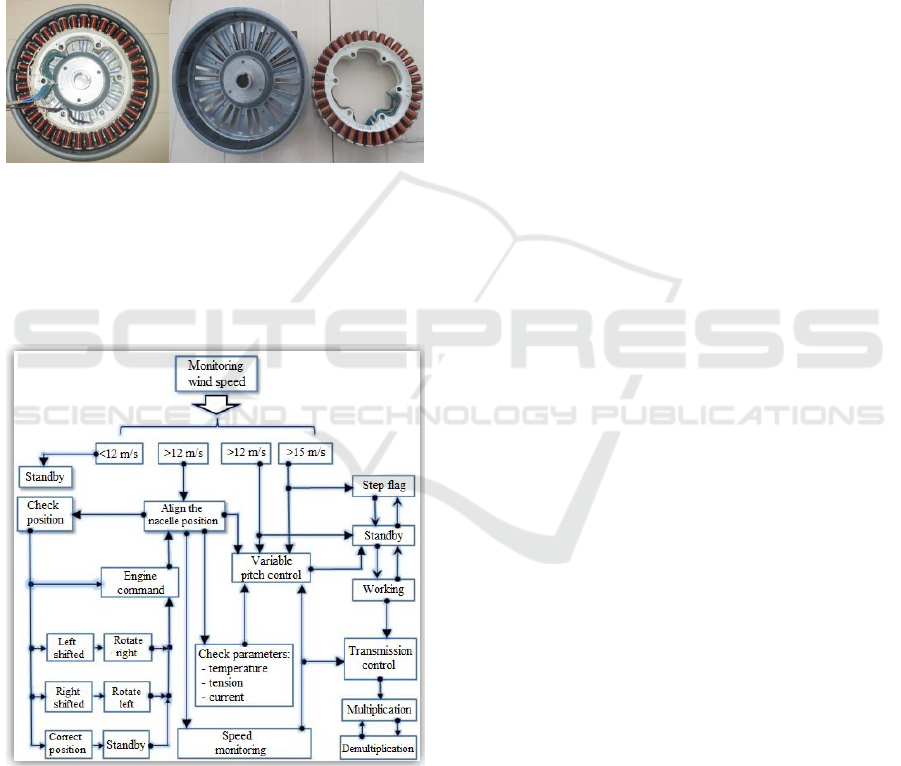
that parameters such as winding conductor material
and section have been changed, the number of coils
and the number of paths. With the modifications we
have made, we have been looking for a large voltage
(about 120 V DC) and a low load current to be cut so
that the winding and transport losses are as low as
possible. By construction, the generator is a three-
phase Y-connection with the permanent magnet rotor
of the ferrous material outdoors, also acting as
cooling fan, and on the inside the stator with 36
notches distributed equally to the three electric phases
(Archer and Jacobson, 2012).
Figure 3: The power generator – left: assembly, centre:
rotor and right: stator.
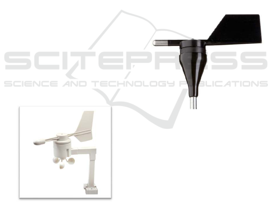
e. THE ELECTRONIC CONTROL AND
COMMAND MODULE
The operating principle is based on the block diagram
of Figure 4.
Figure 4: The block diagram; operating principle.
Running the entire system at rest has the following
steps:
Step 1: The air currents are not present or their
intensity is too low to justify starting the turbine. As
a result of operating tests, the lower limit threshold at
which it was set as starting point is 2.5 m/s, the wind
speed sufficient to start and accelerate the rotor.
Below this minimum threshold, although the rotor is
in motion, the energy collected at the generator
terminals is insignificant, resulting only in idle
operation (John and Julia, 2015).
Step 2: Once the minimum wind speed is
exceeded, the turbine switches to two-stage
operation:
- detecting the wind direction and the aligning
wedge to appropriate position. A particular aspect
is that the platform is given a degree of freedom
of ± 5 ° geometric to the actual direction, thus
avoiding the scenario in which the position
correction is continually attempted during
turbulent air streams. This is more likely to be the
case that, as soon as the nacelle has moved in one
direction for correct alignment, at the smallest
deviation of the steering sensor, the positioning
motor is restarted for a new adjustment, after
which the cycle resume.
- checking and adjusting if necessary the blade step.
As a result of the operating tests, in addition to the
two positions, respectively the working position
and the flag step corresponding to the heads of the
race, it was also required to declare an
intermediate step, which I called a standby
position. The insertion of this intermediate
position produces a positive contribution at the
moment of the rotor start, and after the main shaft
exceeds 60 rpm, corresponding to the propeller,
the blades are switched to the working position
where acceleration to the maximum required by
the conditions forecasts.
Step 3: After the start, the turbine is only allowed
to operate with wind direction correction, monitoring
the input and output speed of the transmission block
until the propeller reaches a set speed of 400 rpm.
From this point the transmission ratio starts to change
in the direction of the increase or decrease as the case
may be, the modification being made gradually and
without the propeller decreasing its speed below the
set limit. In the case of wind gusts that can cause
sudden accelerating, the speed will be automatically
controlled, limited to 450 rpm, by a centrifugal
mechanical system. The wind turbine will be left to
operate in this way as long as the wind speed does not
exceed an alert threshold of 12 m/s (Jacobson and
Archer, 2012).
Step 4: Is a procedure to protect the turbine from
any possible storms. Once the warning threshold of
12 m/s is exceeded for more than 60 seconds, the
blade step will be changed to reduce aerodynamic
performance, being switched to the standby position
where the turbine will continue to operate but the
System for Controlling a Wind Turbine
221
propeller speed will be reduced. In the same way, if a
15 m/s alert threshold is exceeded, the propeller will
pass the flap, the tube will enter dynamic braking
where this time the air currents will block the rotation
of the propeller until it stops completely (Bie and
Zhang, 2012).
The engine control system is built around a
microcontroller that, according to initial instructions,
has the task of modifying or correcting the current
status of the entire system. We can say about the
microcontroller that its functions are divided into two
main categories, namely the command function that
uses the output signals, the final result being the
motors' operation as the case may be, and the
monitoring function which, by means of some sensors
and transducers, interprets the operating parameters.
The monitoring function pursues:
- direction and speed of the wind;
- aligning the platform in the direction of the air
currents;
- propeller and generator shaft speed;
- operating parameters of the generator: voltage,
current, temperature;
- maintaining self-regulation systems at work
intervals (race limits).
2.2 The Sensors Used in System Design
a. THE WIND SENSOR
For wind speed monitoring, a digital unit
incorporating the anemometer and weathervane was
used on the market under the name of TX20 SENZOR
model developed by La Crosse Technology Ltd.
Figure 5: The wind sensor.
The sensor will transmit the data every 2 seconds
as long as pin 3, DTR, is connected to GND. The data
chart contains 41 bits divided into 6 data sections. The
transmission is for 49.2 ms, the duration of one bit
being 1.2 ms.
b. THE POSITION SENSOR
The role of this sensor is to align the propeller in the
wind direction. It is also a wind sensor, i.e. a
weathervane, but in which the output signal is
analogous, used in a particular way in that the
mounting base is movable to the ground. The
Weathervane is mounted on the platform body, which
in turn is movable around the axis of the tower. In the
correct alignment position, the mobile element must
be aligned halfway through the time the sensor can
detect wind direction deviations. A deviation in either
direction from this position will detect what triggers
the rotation of the platform as well as the base of the
sensor, the mobile element being maintained in the
wind position. In this way, the weathervane returns to
the correct position by turning the nacelle off. The
phenomenon is repeated whenever position
corrections are needed. The type of sensor used is a
weathervane, known as wind wane model NRG #
200P.
Figure 6: The weathervane NRG model # 200P.
The mobile element of the weathervane operates
an internal potentiometer in a complete rotation of
360 degrees and can be deflected by winds at speeds
of 1 m/s.
The potentiometer has an internal resistance of 10
KΩ and can be directly supplied to a voltage in the
range of 1 ÷ 15V DC, the output signal being a
voltage proportional to the wind direction. From
constructive limitations and because a degree of
freedom of 360 degrees is desired, for an interval
between 8 ÷ 10 geometric degrees the sensor output
is null, in this area the potentiometer cursor does not
have a conductive film continuity. This is an
impediment if the output signal is to be interpreted
directly by a microprocessor; in the possibility that
the potentiometer cursor would be in the area called
dead band, the output signal is missing, which may
MoMa-GreenSys 2019 - Special Session on Modelling Practical Paradigms of Green Manufacturing Systems
222
cause operating errors. Although the probability of
error is small, the dead band has a range of
approximately 8 ÷ 10 geometric degrees, which
means 2.75% of the measurement range, they must be
eliminated or reduced as much as possible (Al-
Muhaini and Heydt, 2013).
c. THE SPEED SENSORS
Changing the transmission ratio and the variable pitch
of the propeller is determined by the rotation speed of
the propeller shaft and the generator. In this respect,
the speeds of the two shafts must be monitored
throughout the turbine operating mode. There are
several types of sensors specifically developed to
determine the speed of rotation of the trees, among
them, those with the longest use being non-contact
sensors. According to the output signal type, the
sensors can be classified into capacitive, inductive or
Hall Effect sensors. For slow speed shafts, rotation
speed detection sometimes uses reed relays, but the
blades of the contact are subject to premature aging
due to the large number of triggers to which it is
subjected. The types of sensors used are produced by
Honeywell under the SS411P encoding.
To trigger the sensor we used permanent magnets,
four of which are fixed to a disc mounted on the shaft
for which the speed is determined. Magnets are fixed
to the disk table at equal distances with alternating
poles. During rotation of the shaft and the magnets,
they will enter the sensor trigger area, the output
signal becoming a rectangular signal that will have
two periods during a complete rotation. The
frequency of the output signal is directly proportional
to the rotation speed of the shaft, so its mathematical
computation can be determined by the formula:
60
2
f
n
(1)
where f is the signal frequency and n is the speed
Figure 7: The propeller shaft switch disk.
Similarly, the rotation movement of the drive
motor of the transmission mechanism is detected,
indicating that this time the sensor is of the unipolar
type and on the disk mounted on the shaft are
diametrically opposed on the circumference only two
magnets with the same pole magnetically pointing
towards the sensor. Thus, every half-turn is sensed by
a low level of the output signal.
The same model of the unipolar Hall sensor, in the
same configuration, is used to detect positions where
the blades are in the position we named above the
standby position and the alignment of the platform to
a reference point. For the interpretation of output
signals, it should be noted that they are at a low level
when they are at points of interest and at a high level
in the rest (Conti and Rizzo, 2015).
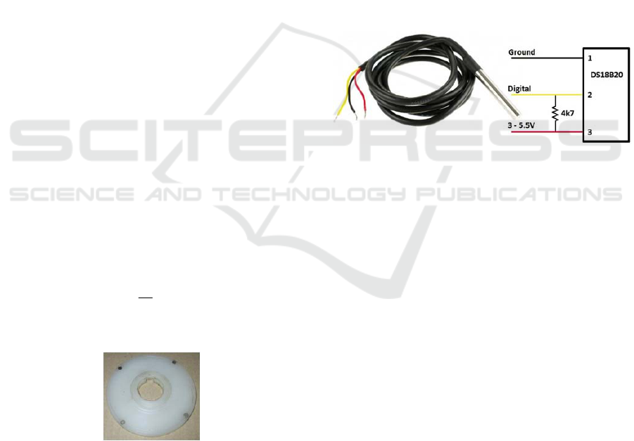
d. THE TEMPERATURE SENSOR
Over a long period of operation, the internal
temperature of the generator may reach critical values
that may result in its destruction. To avoid possible
damage or troubleshooting due to a high temperature
regime, it is preferable to switch the temperature
generator above the threshold. Thus, the stator
temperature should be monitored throughout the
operation.
Figure 8: The temperature sensor. Model DS18B20.
Variants of temperature-sensitive elements that
are compatible with the microcontroller and without
the need for complex processing of signal processing
are the thermistor, analogue sensor LM35 or
DS18B20 digital sensor, the latter being the one to be
used. The main advantage is that for communication
with the microprocessor, data transmission from the
device is done on a single wire (and mass, GND).
e. THE CURRENT SENSOR
Electrically operated mechanisms have an average
degree of complexity, and for undesirable reasons,
malfunctions may occur, resulting in an increase in
engine current absorbed above the normal operating
range. These situations would be likely to cause
blockage, defeat limiters or a high degree of wear on
the engine. Maintaining under voltage at currents well
above normal operating limits would cause excessive
engine heating leading to irreparable damage, and
other elements in the supply circuit may be affected.
Elimination of these possible situations is
accomplished by monitoring the current in the motor
circuits, in this sense, by introducing a current sensor
into the circuit. For easy deployment, we used a
System for Controlling a Wind Turbine
223

sensor model built on an integrated circuit developed
by Allegro MicroSystems, under ACS712 encoding.
It is an SMD small integrated circuit in the SOIC8
capsule, the current detection being based on the
linear Hall Effect. The sensor is invasive, requiring
interruption of a supply line, and can detect current in
both AC and DC circuits.
Figure 9: The current sensor. Model ACS712.
f. THE VOLTAGE SENSOR
For complete monitoring of the entire system, it is
necessary to interpret the electrical parameters of the
generator. If the implementation of the output current
detection function is somewhat considered to be easy,
with different variants of inversion or non-invasive
AC sensors, measuring output voltage of the
generator with a microcontroller imposes certain
restrictions precisely because of the operation. The
output voltage is a variable signal in both amplitude
and fecundity, the maximum values being considered
dangerous to be detected directly. Thus, during
operation, when weather conditions allow, at the
terminals of the three-phase generator, for current
configuration of connections, weights can be
recorded in the range 0 ÷ 90 V AC with frequencies
proportional to the voltage in the range 0 ÷ 400 Hz.
The maximum possible voltage is high enough to
reach values considered dangerous, which is why
indirect measurement is recommended to determine
its value. Due to the variable frequency, it is not
possible to use a low voltage transformer to obtain a
low level signal so that it can be processed by the
microcontroller, the frequency variation limits cause
them to malfunction, being well above tolerances.
The voltage collected from the generator
terminals is rectified and filtered, then applied to a
resistive divider dimensioned so that for the
maximum possible applied value, the divider's mean
point does not exceed the 12 V DC threshold.
However, there is a possibility that, due to the lack of
a consumer, the tension will increase much, even
beyond the limit. To avoid damaging the circuit
caused by an accidental voltage, even if there is an
increase above the 12V level, it will be stabilized by
a Zenner diode.
Taking into account the fact that, in order to be
interpreted by the microcontroller, the input signal
can be a DC voltage, for detecting the voltage level of
the generator we proposed and implemented the
following scheme:
Figure 10: The voltage sensor. Electronical scheme.
The method has the advantage of galvanic
separation of power circuits from signal circuits and
prevents the destruction of the microcontroller if the
turbine enters the operating mode in the absence of
the supply voltage of the microcontroller by
introducing external voltages on the signal port.
g. THE MICROCONTROLLER
The Arduino Mega 2560 development board has 54
digital input / output pins (of which 14 can be used as
PWM outputs), 4 UART serial ports, 16 analog
inputs, a USB connection, a 16 MHz quartz crystal
oscillator, a power jack and a reset button.
The 54 digital pins can be used as outputs or
inputs with the digitalRead (), digitalWrite () and
pinMode () functions. These digital pins use the
digital signal in which the 0 logic is represented by
the absence of voltage and 1 logic having the voltage
level of 5V. Analog pins provide a resolution of 10
bits meaning 1024 different values. These pins
measure voltages between 0V and 5V.
Arduino Mega 2560 has facilities for
communication with a computer, other
microcontrollers or other Arduino cards. The Arduino
software includes a serial monitoring that allows
simple textual data to be received or sent to the
development board.
The microcontroller is programmed to take data
from the sensors to display them using the LCD
module. As an example, see figure 11.
Figure 11: Display data taken from sensors.
MoMa-GreenSys 2019 - Special Session on Modelling Practical Paradigms of Green Manufacturing Systems
224

3 CONCLUSIONS
The system was tested under real conditions with
good results for initial tests under laboratory
conditions. At the same time, a second electronic
module was developed to complement the system, its
functions being communication, the data taken being
processed and displayed on a display. The results are
promising, so we can consider the test period ended
after the entire system is tested under realistic
conditions in a time frame that includes both a cold
season and a warm season.
The wind turbine will be used to provide the
electricity needed for a home or small production hall.
REFERENCES
U.S. Energy Information Administration. Web. 29 May
2013, http://www.eia.gov/
World Energy Council. 2010 Survey of Energy Resources,
London, UK.
Wagner, H.-J., 2017. Introduction to wind energy systems,
The European Physical Journal Conferences, 148,
pp.1-16.
Jianbo Y., Qunyi Liu, Xin Li, and Xiandan Cui., 2017.
Overview of Wind Power in China: Status and Future,
Sustainability, 9, 1454.
Suaad J., 2013. Environmental Impacts of Wind Energy,
Journal of Clean Energy Technologies, Vol. 1, No. 3,
pp.251-255.
Archer C.L. and Jacobson M.Z. 2005. Evaluation of global
wind power, Journal of Geophysical Research.
John O. D., Julia R. G., Jeffrey R. K., Parviz M., and Jifeng
P., 2015. A new approach to wind energy:
Opportunities and challenges, AIP Conference
Proceedings, pp.51-57.
Jacobson M.Z. and Archer C.L. 2012, Saturation wind
power potential and its implications for wind energy.
Proceedings of the National Academy of Sciences of
the USA.
Bie Z., Zhang P., Li G. 2012,Reliability Evaluation of
Active Distribution Systems Including Microgrods,
IEEE Trans. Power Syst., vol.27, no.4, pp.2342-2350.
Al-Muhaini M. and Heydt G.T. 2013, Evaluating future
power distribution system reliability including
distributed generation, IEEE Trans. Power Del., vol.28,
no.4, pp.2264-2272.
Conti S., Rizzo S.A. 2015, Reliability assessment of
distribution systems considering telecontrolled
switches and microgrids, IEEE Trans. Power Syst.,
vol.29, no.2, pp.598-607.
System for Controlling a Wind Turbine
225
