
Hybrid Force/Position Control of a Very Flexible Parallel Robot
Manipulator in Contact with an Environment
Fatemeh Ansarieshlaghi
a
and Peter Eberhard
b
Institute of Engineering and Computational Mechanics, University of Stuttgart,
Pfaffenwaldring 9, 70569 Stuttgart, Germany
Keywords:
Flexible Parallel Robot, Position Control, Force Control, Impedance Control.
Abstract:
There are many applications for robot manipulators and these tasks are complicated when they have interaction
with environments and humans. This paper investigates a novel strategy to control a very flexible parallel
manipulator interacting with an environment. The controller is complicated when the used robot manipulator
is a flexible multibody dynamics system and the flexibility shall be taken into account in the modeling and
controlling process. Also, interaction with an unknown environment is another challenge of our research.
Hence, a sophisticated controller is designed to overcome the respective challenges. To this end, a hybrid
force/position control strategy is utilized. Therefore, two controllers based on the rigid and flexible models
of the robot are designed and implemented to interact with a surface. The simulation results show that the
controllers based on the flexible model have a better performance than those based on the rigid model and
successfully track a trajectory and interact with an environment.
1 INTRODUCTION
Light-weight manipulators attract a lot of research
interest because of their complementing advantages.
The advantages of light-weight robots include low en-
ergy usage, less mass, and often high working speeds.
However, due to the light-weight design, the bod-
ies have a significant flexibility which yields unde-
sired deformations and vibrations. These manipula-
tors can be modeled as flexible multibody systems
and their flexibility must be taken into account in the
controller design. The flexible multibody system with
significant deformations complicates the control de-
sign because there are more generalized coordinates
than control inputs. This complicated controller has
a more complex design when the robot interacts with
an environment. The controller shall be able to regu-
late the interaction force and move along the surface
at the same time. In order to obtain a high perfor-
mance in the end-effector’s contact part, an accurate
and efficient model as well as a nonlinear controller is
necessary.
In this research, to investigate the controller a flex-
ible robot available in hardware in our laboratory is
a
https://orcid.org/0000-0003-2693-0882
b
https://orcid.org/0000-0003-1809-4407
used. This robot has a λ-shape and its links are
very flexible. In previous researches on this robot,
only its modeling and position control were inves-
tigated. The modeling is described in (Burkhardt
et al., 2013a). Also, an experimental study on the
modeling and the modeling improvement were done
in (Burkhardt et al., 2014) and (Ansarieshlaghi and
Eberhard, 2017). The position control of this system
can be done by a model-based or non-model-based
feedback controller. Non-model-based feedback con-
trollers in joint space were investigated in (Burkhardt
et al., 2014) and (Morlock et al., 2016) and the flexi-
ble model based nonlinear feedback controller in joint
space was investigated in (Ansarieshlaghi and Eber-
hard, 2018b). An experimental study of the rigid
model-based controller on the lambda robot in the
workspace was also done in (Morlock et al., 2017).
In contrast, in the previous works, here, a feed-
back controller of the lambda robot in work space is
desired. Also, a part as a contact force regulator is
added to the position controller in order to control
the interaction with an environment. For interacting
with an environment, control of the contact force in
the interactive part is required. There are two meth-
ods to control this force, i.e., direct and indirect con-
tact force control methods. In the direct approach, the
controller regulates the force with a control loop and
Ansarieshlaghi, F. and Eberhard, P.
Hybrid Force/Position Control of a Very Flexible Parallel Robot Manipulator in Contact with an Environment.
DOI: 10.5220/0007833400590067
In Proceedings of the 16th International Conference on Informatics in Control, Automation and Robotics (ICINCO 2019), pages 59-67
ISBN: 978-989-758-380-3
Copyright
c
2019 by SCITEPRESS – Science and Technology Publications, Lda. All rights reserved
59

using feedback of the force measurement and desired
value of the force. For this method, an explicit model
of the interaction environment is required, see (Luh
et al., 1983). In the indirect force control methods,
the force is controlled via position controller as an
impedance (Hogan, 1985).
The contact force control of the light weight
robots is very important task and there are many ap-
plications on this topic, e.g., industrial (Schindlbeck
and Haddadin, 2015; Suarez et al., 2018), surgical (Li
et al., 2018; Sandoval et al., 2018; Kamikawa et al.,
2018), or soft robotic application (Vogel et al., 2015).
Also, the contact force control of a flexible robot is in-
vestigated with one flexible link in (Endo et al., 2017;
Feliu-Talegon et al., 2019) and for multi flexible links
in (Suarez et al., 2018).
In our research, a hybrid force/position con-
trol is designed using the impedance controller ap-
proach (Siciliano and Khatib, 2016; Jung et al., 2004)
for a very flexible robot manipulator.
The novelty of this work is that a nonlinear flex-
ible model based position controller of the lambda
robot in workspace is designed. Then, this posi-
tion controller is combined with an impedance part
in order to have a controller architecture that can be
used for controlling the position and acting force of
the end-effector’s contact part during its interaction
with an environment. The impedance part computes
a new end-effector position based on the measured or
estimated force and the position of the end-effector.
Therefore, the impedance part generates a new end-
effector position for tracking by the position con-
troller part.
The nonlinear flexible model based controller in
Cartesian space is simulated and compared with the
rigid model based one. To test the designed pure
position controller, the end-effector tracks a trajec-
tory with low and high speed. Comparison results
show that the flexible model based controller can
track a trajectory with much higher accuracy than the
rigid based and it shows very high tracking perfor-
mance. To investigate the hybrid force/position con-
troller, the end-effector’s contact part interacts with a
flat surface in two scenarios, interaction with a known
and an unknown environment. Simulation results on
the lambda robot show that the flexible based con-
troller has better performance than the rigid based for
both scenarios and the robot using this flexible based
impedance controller can apply the desired force dur-
ing moving along the surface with high accuracy.
The paper is organized as follows: Section 2 de-
scribes the robot, i.e., its mechanical and electrical
parts. Section 3 includes the modeling of the flexi-
ble parallel lambda robot. Section 4 explains the ar-
chitecture of the nonlinear controller, i.e., the position
controller and impedance controller. In Section 5, the
proposed nonlinear controller is simulated and the re-
sults are discussed.
2 FLEXIBLE LAMBDA ROBOT
The used lambda robot is a simple parallel robot ma-
nipulator. This robot has highly flexible links. The
end of the short link is connected in the middle of
the long link using rigid bodies. This connection cre-
ates a closed loop kinematics constraint that causes
the parallel configuration of the robot. This robot has
two prismatic actuators connecting the links to the
ground. The links are connected using passive rev-
olute joints to the linear actuators. Another revolute
joint is used to connect the short link and the middle
of the long link. An additional rigid body is attached
to the free end of the long link as an end-effector. The
drive positions and velocities are measured with two
optical encoders. Three full Wheatstone bridge strain
gauge sets are attached on the long flexible link to
measure its deformation. The lambda robot configu-
ration shown in Figure 1 has been built in hardware,
see (Burkhardt et al., 2014) at the Institute of Engi-
neering and Computational Mechanics of the Univer-
sity of Stuttgart.
The electrical part of the hardware includes some
power supplies for motors, strain gauge’s ampli-
fiers, digital/analog input-outputs boards, one Speed-
goat target, a host computer, etc. For control-
ling the robot, the online control is done with
a Speedgoat performance real-time target machine
running a Mathworks xPCtarget kernel, which is
called Simulink Real-Time since Matlab R2014a.
Also, to observe the controller progress a graphical
user interface is available for the input, output, safety
logic of the lambda robot and their communication.
3 MODELING OF THE
FLEXIBLE LAMBDA ROBOT
The modeling process of the flexible manipulator with
λ configuration can be separated into three major
steps. First, the flexible components of the system
are modeled with the linear finite element method in
the commercial finite element code ANSYS. Next, in
order to control the λ robot, the degrees of freedom
of the flexible bodies are reduced. Therefore, model
order reduction is utilized. Then, all the rigid and flex-
ible parts are modeled as a flexible multibody system
ICINCO 2019 - 16th International Conference on Informatics in Control, Automation and Robotics
60
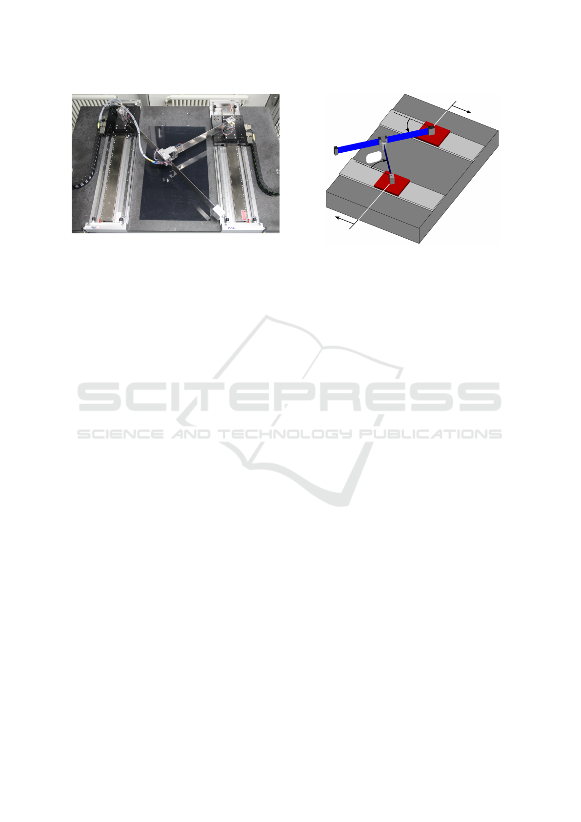
Figure 1: Mechanical setup of the flexible parallel lambda
robot.
with a kinematic loop using the generalized coordi-
nates q ∈ R
5
as
M (q) ¨q = f(q, ˙q) + B(q)u + C
T
(q)λ , (1a)
c(q) = 0 . (1b)
The symmetric, positive definite mass matrix
M ∈ R
5×5
depends on the joint angles and the elastic
coordinates. The vector f ∈ R
5
contains the gener-
alized centrifugal, Coriolis and Euler forces, and the
vector of applied forces and inner forces due to the
body elasticity. The input matrix B ∈ R
5×2
maps the
input vector u ∈ R
2
to the system. The constraint
equations are defined by c ∈ R
2
. The Jacobian ma-
trix of the constraint C = ∂c(q)/∂q ∈ R
2×5
maps the
reaction force λ ∈ R
2
due to the kinematic loop.
The flexible lambda robot is modeled as a flexi-
ble multibody system in Neweul-M
2
(Burkhardt et al.,
2013b). The simulated model of the lambda robot is
shown in Figure 2, see also (Burkhardt et al., 2013a;
Ansarieshlaghi and Eberhard, 2018a).
While the system has a kinematics loop as a con-
straint in Equation (1b), the system accelerations ¨q
can be divided into dependent ¨q
d
∈ R
2
and indepen-
dent ¨q
i
∈ R
3
coordinates and the system constraints
can be written as
¨c = C ¨q + c
00
= C
i
¨q
i
+ C
d
¨q
d
+ c
00
(2)
where q
d
= [α
1
,α
2
]
T
, q
i
= [s
1
,s
2
,q
e
]
T
, C
d
and C
i
are
dependent and independent parts of the Jacobian ma-
trix of the constraint and c
00
presents local acceler-
ations due to the constraints. The parameter q
e
de-
scribes elastic coordinates of the flexible long link.
Based on Equation (2), the system’s generalized ac-
celeration can be formulated as
¨q =
¨q
i
¨q
d
=
I
3×3
−C
−1
d
C
i
¨q
i
+
0
3
−C
−1
d
c
00
= J
c
¨q
i
+b
00
.
(3)
s
1
s
2
α
2
α
1
end-effector
Figure 2: Mechanical model of flexible parallel robot.
Here, J
c
and b
00
are Jacobian matrix and local ac-
celerations due to rewriting the generalized accelera-
tion based on the system constraints. Finally, by left-
side multiplication with the transposed of the Jaco-
bian matrix J
c
and replacing ¨q by Equation (3), Equa-
tion (1a) can be written as
J
T
c
M (J
c
¨q
i
+ b
00
) = J
T
c
(f + Bu + C
T
(q)λ) (4)
while the multiplication matrix of the rewritten Jaco-
bian matrix and the Jacobian matrix of the constraint
is J
T
c
C
T
= 0, the equation of motion (1a) can be de-
termined, see (Burkhardt et al., 2013a), by
¯
M ¨q
i
=
¯
f +
¯
Bu. (5)
In Equation (5), the inertia matrix
¯
M ∈ R
3×3
is
J
T
c
MJ
c
, the input matrix
¯
B ∈ R
3×2
is J
T
c
B, and the
vector
¯
f ∈ R
3
is J
T
c
(Mb
00
+ f ) from Equation (4).
The independent generalized acceleration can be ob-
tained by
¨q
i
=
¯
M
−1
(
¯
f +
¯
Bu). (6)
Equation (6) will be used for the workspace de-
scription of the system dynamics and designing the
nonlinear feedback controller.
Joint Space to Work Space
Transformation
The system kinematics is formulated as
x = s(q
i
), (7)
where x ∈ R
2
is the end-effector position and s ∈ R
2
is a nonlinear function of the independent system co-
ordinates q
i
. The velocity and acceleration of the end-
effector in the Cartesian space are calculated by the
time derivative of the end-effector position function
in Equation (7) by
˙x = J ˙q
i
, (8a)
¨x = J ¨q
i
+
˙
J ˙q
i
, (8b)
Hybrid Force/Position Control of a Very Flexible Parallel Robot Manipulator in Contact with an Environment
61
In Equation (8b), J and
˙
J are the Jacobian ma-
trix of the robot kinematics and its derivative. Finally,
by replacing ¨q
i
from Equation (6) to Equation (8b),
the dynamics description can be found in workspace
coordinates with
¨x = J(
¯
M
−1
(
¯
f +
¯
Bu)) +
˙
J ˙q
i
. (9)
Equation (9) is used to control the position of the
end-effector as well as the contact force during the
interaction with an environment.
4 CONTROL OF THE FLEXIBLE
LAMBDA ROBOT
The lambda robot controller is separated into feedfor-
ward and feedback controller parts. In the feedfor-
ward part, the desired signals are calculated based on
the robot work space, the joint space, the kinemat-
ics, and the dynamics constraints of the robot. The
kinematics constraints include the maximum velocity,
position of the robot joints, and the closed loop kine-
matics. The maximum current, the maximum acting
force, and the maximum flexible coordinates oscilla-
tion amplitude are defined as dynamics constraints,
see (Seifried et al., 2011). The feedback control part
computes the lambda robot inputs based on the feed-
back linearization method (Khalil, 2002) using the
nonlinear dynamics of the robot, the measured states,
and the computed end-effector position.
The feedback controller part based on the appli-
cation can have three parts, i.e., a position controller,
an impedance controller, and the forward kinematics
or an observer. In the simplest case, the controller in-
cludes only the position controller in the joint space,
see (Eberhard and Ansarieshlaghi, 2019). As a next
case, the feedback controller includes a position con-
troller and an observer when the joint space controller
of the robot is desired, see (Ansarieshlaghi and Eber-
hard, 2018b). Also, for controlling the end-effector
position in the workspace, the position controller and
its combination with the forward kinematics is re-
quired. In the most complicated case, the feedback
controller is a combination of the position controller,
the impedance controller, and the forward kinematics
part. This combination is used when the contact part
of the robot end-effector has an interaction with an en-
vironment in the Cartesian space. Therefore, the joint
space to the workspace transformation of the system
dynamics is required and computed by Equation (9).
Based on the robot work space, the position con-
troller shall generate the robot’s inputs in Cartesian
space. Therefore, the control law is obtained as
u = −
¯
B
−1
(
¯
f +
¯
MJ
−1
(
˙
J ˙q
i
−K
P
e − K
D
˙e)). (10)
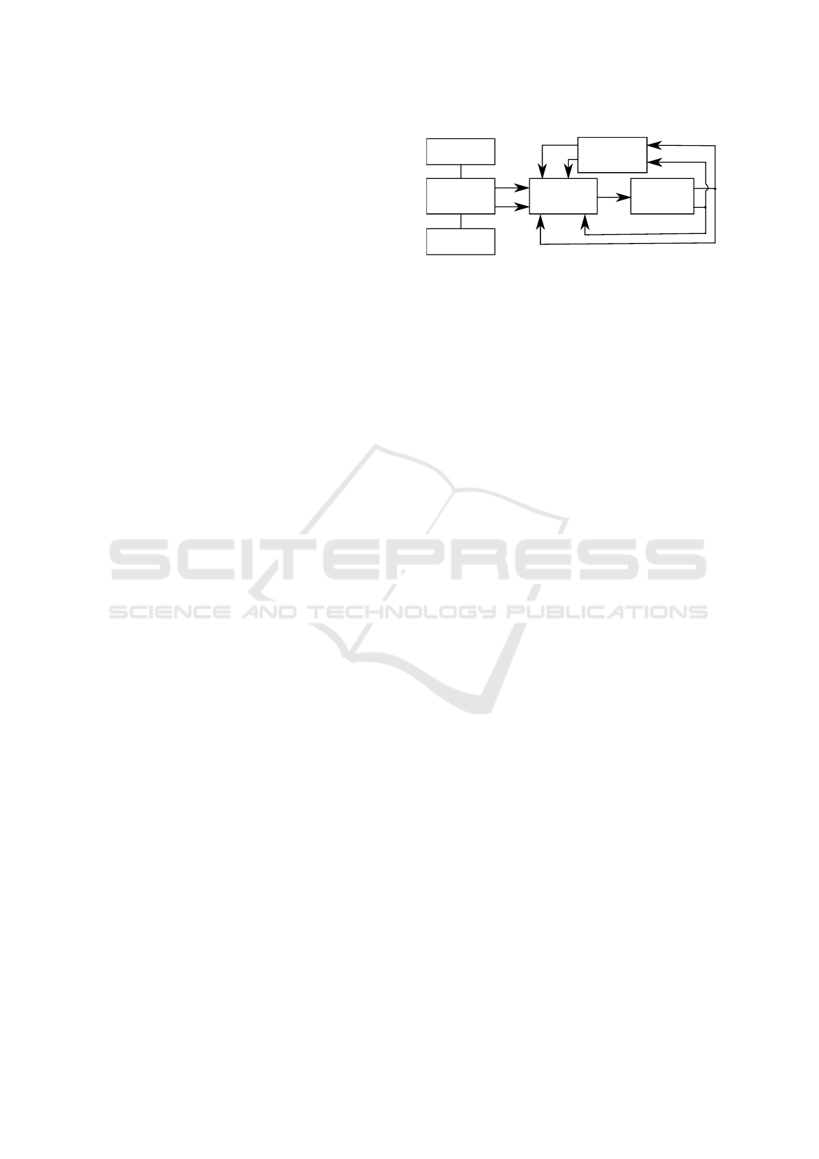
forward
kinematics
lambda
q
i
˙q
i
x
˙x
x
d
˙x
d
u
robot
controller
position
controller
feedforward
kinematics
dynamics
constraint
constraint
Figure 3: Nonlinear position control structure.
The error and its dynamics are calculated by e =
x − x
d
and ˙e = ˙x − ˙x
d
where x
d
is the desired value
of x, consequently ˙x
d
is the desired value for ˙x. The
desired trajectories of the end-effector can be com-
puted based on the robot workspace as x
d
and ˙x
d
.
The matrices K
P
and K
D
correspond to the weight-
ing of feedback errors and can be designed via the
LQR method or tuned by hand. Also, they should sat-
isfy the stability conditions for nonautonomous sys-
tems as a uniform stability, based on the Lyapunov
theorem.
The lambda robot is an underactuated robot and
the input matrix
¯
B is therefore not of full row rank.
Thus, the inverse of the input matrix is not so straight-
forward to calculate. Therefore, the existing left-
inverse is used as a pseudo-inverse to yield
¯
B
¯
B
−1
=
I. The vector u presents the control input of the robot
manipulator and that is the output of the designed po-
sition controller based on the feedback linearization
method. Figure (3) shows the control structure for
controlling the end-effector position in order to track
a trajectory in Cartesian space.
The position control for all scenarios as the po-
sition or the force/position controller is same as Fig-
ure 3. The only difference between the position and
hybrid force/position controller is the desired input
signal to the controller. This structure is extended to
control the contact force to interact with an environ-
ment. However, the interactive environment can be a
known or an unknown surface.
The robot has only two actuated joints and can just
move in the horizontal plane. Hence, the end-effector
can only interact with an environment in its move-
ment directions in the horizontal plane. That means
that the end-effector shall have contact in one or both
directions that the end-effector moves. The position
and acting force are dependent and shall be controlled
dependently. So the contact force is controlled by us-
ing indirect control methods. One of the approaches
that is used for indirect force control is the impedance
controller method, see (Siciliano and Villani, 1999;
Siciliano and Khatib, 2016).
Based on the feedback controller structure pre-
sented in Figure 3, the new feedback controller struc-
ICINCO 2019 - 16th International Conference on Informatics in Control, Automation and Robotics
62
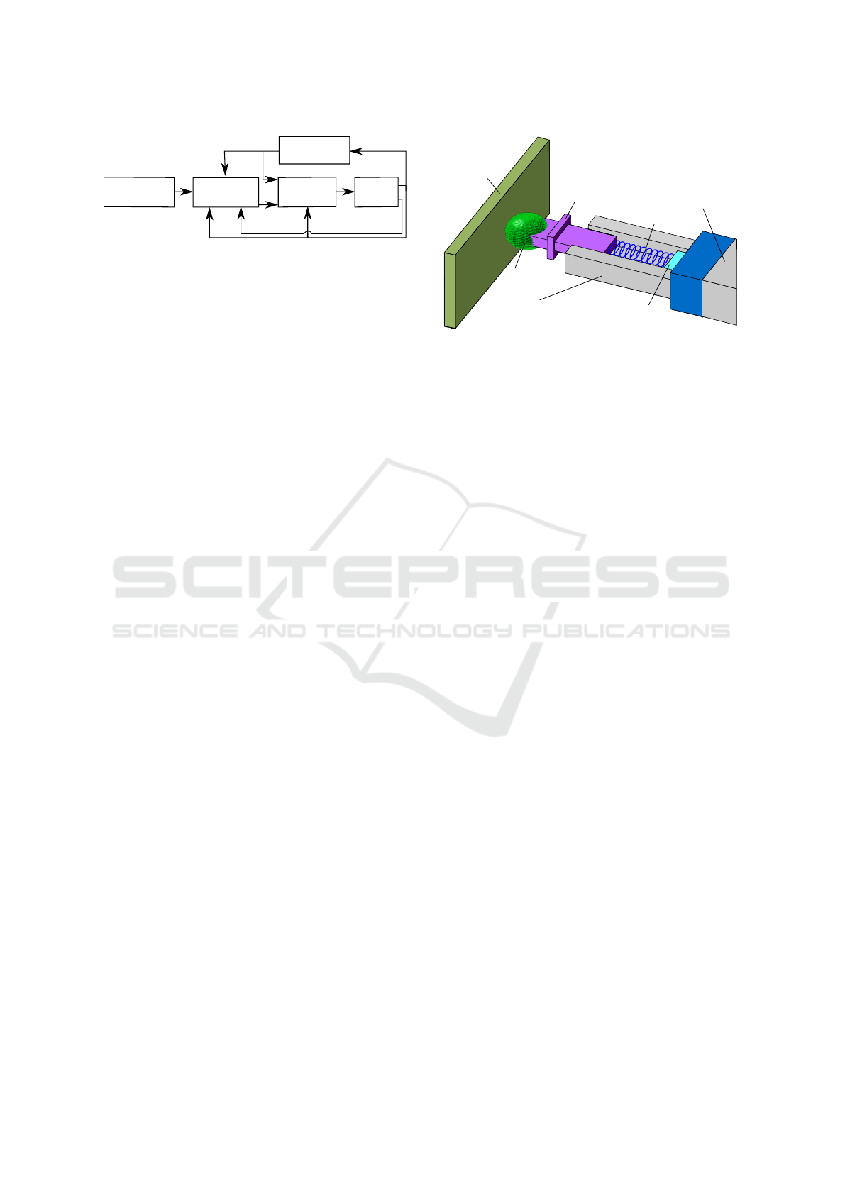
forward
kinematics
lambda
robot
controller
position
controller
impedance
controller
feedforward
q
i
˙q
i
x
˙x
x
0
d
˙x
0
d
u
f
y
d
Figure 4: Force/position control structure for interacting
with an environment.
ture is developed to control the force and position at
the same time. The developed new feedback con-
troller is shown in Figure 4.
The new feedback controller is composed of the
position controller, force controller, and the forward
kinematics part as a hybrid force/position controller.
In Figure 4, the feedforward controller computes the
desired values y
d
based on the interactive environ-
ment that can be a known or an unknown surface. For
a known scenario, the desired values y
d
are the po-
sition of the surface x
d
, the moving velocity on the
surface ˙x
d
, and the magnitude of the acting force on
the surface f
d
in Cartesian space. The desired values
for the unknown case are the magnitude of the moving
velocity v
d
and the acting force f
d
on the surface.
The impedance part of the feedback controller
computes a new desired position and velocity of the
robot’s end-effector based on the desired values by
the feedforward controller, the measured states q
i
and
˙q
i
, the contact force f , and the computed or observed
position of the contact part by the forward kinematics.
The position controller acts as the last part in Figure 3
based on its input signals and the dynamics model of
the robot.
In order to interact with an environment, a tool
that is shown in Figure 5 is designed and installed on
the end-effector in Figure 2.
The basic idea of the designed tool is to control the
contact force during moving on the surface. There-
fore, based on the robot configuration and its degrees
of freedom, the contact part’s force should be defined
as a function of the end-effector position. Thus, the
tool is designed to be a transfer function, to convert
the interaction force of the contact part to the end-
effector position displacement. This transfer tool is
designed such that the acting force accurately and re-
liably is transferred to the force sensor. The tool in-
cludes a body for interacting as a contact part, a mov-
able body which is connected to a spring for trans-
ferring the contact force, a force sensor to measure
the interacting force, and a structure to constrain the
spring in the force direction and to avoid its bending
and deformation. Also, for the movable body, a safety
stop is considered to limit the measured force and pro-
tect the force sensor.
contact
surface
contact
body
force
sensor
safety stop
spring
motion constraint
to avoid bending
end-effector
Figure 5: Designed tool for interacting with an environ-
ment.
Impedance Control
Impedance control is a method used for indirect force
regulation. The impedance refers the dynamic rela-
tion of the motion and contact force of the manipula-
tor during an interaction with an object. It means that
the impedance controller transfers the contact force as
a function of the contact part’s position and then, the
position controller regulates it.
In this work, for modeling the impedance part
only a spring with stiffness k is used. The free
length of the designed tool is l
0
. For controlling the
contact part’s position and its acting force, the end-
effector position shall be controlled. For this goal,
based on the desired input y
d
, measurement signals
y = [q
i
, ˙q
i
, f ]
T
, and the feedforward kinematics, the
new desired end-effector position and velocity are ob-
tained as
x
0
d
= g
1
(y
d
,y,x, k, l
0
), (11a)
˙x
0
d
= g
2
(y
d
,y, ˙x). (11b)
The important point in this work is that the environ-
ment model is unknown and we do not have any infor-
mation about its shape. The environment can be flex-
ible, deformable, movable, or compressible. The only
difference between a known and an unknown environ-
ment for this work is, when the position and moving
velocity on the surface is known, the environment is
named known. For an unknown environment, only
the magnitude of moving velocity is given and based
on the measured force, the impedance part can distin-
guish wherever that the contact body is in contact or
not. Based on this idea, it computes the new desired
values (x
0
d
, ˙x
0
d
).
After introducing the environments that the robot
can interact with, now parameters that are used for
updating the new desired values are defined. The pa-
rameters are determined based on the inputs of the
functions g
1
and g
2
of Equation (11) in Figure 6.
Hybrid Force/Position Control of a Very Flexible Parallel Robot Manipulator in Contact with an Environment
63
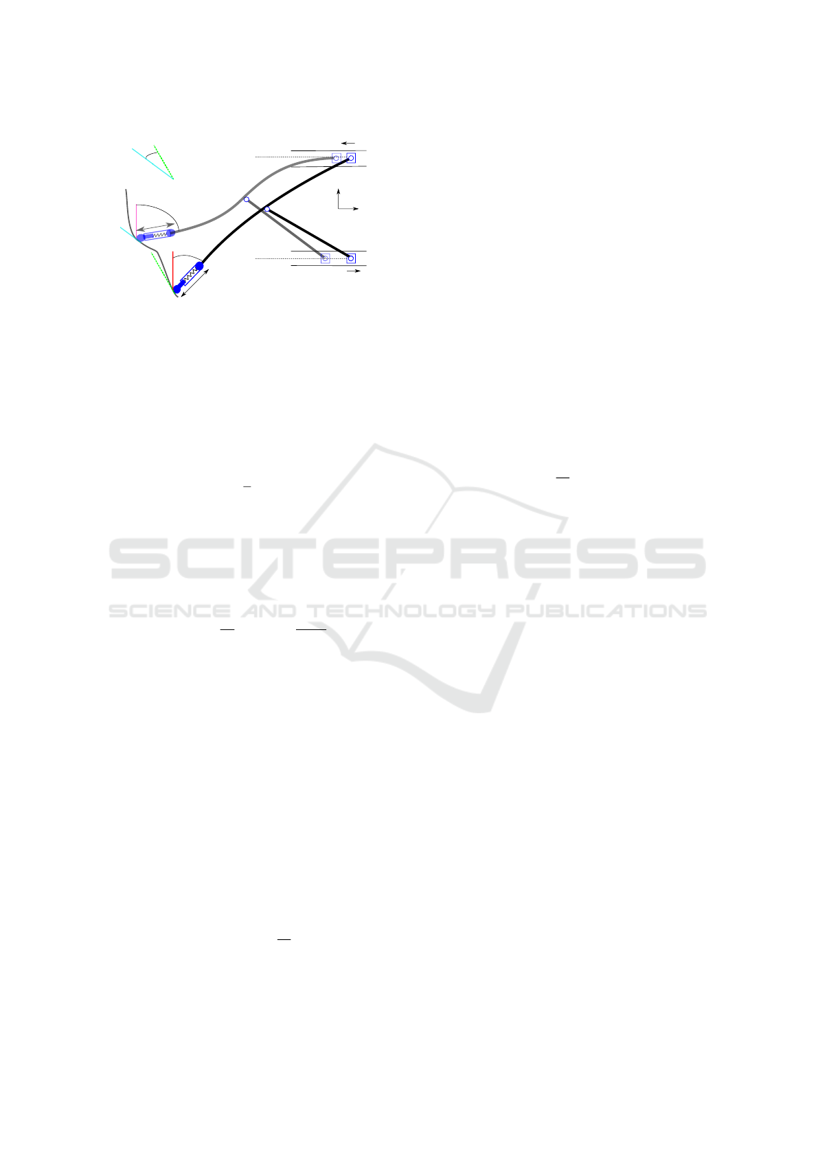
s
1
s
2
β
2
l
2
β
1
f > f
d
l
1
f < f
d
x
y
θ
Figure 6: Schematic view of the lambda robot in contact
with an environment.
Figure 6 shows a schematic view of the lambda
robot and its designed tool in interacting with an en-
vironment. The designed contact tool’s length can
change based on the acting force. The angles β
1
and
β
2
are between the y-direction of the global coordi-
nate system and the robot end-effector in two config-
urations. It is calculated by
β = g
4
(q
i
) =
π
2
− (α
1
+ rq
e
). (12)
The constant r is the gain for the elastic rotation
and displacement of the long flexible link. The angle
θ is computed based on the position of the robot end-
effector at the current sample time t and the previous
sample time t − 4t
θ =g
3
(x
t
,x
t−4t
) (13)
=arctan(
x
x
t
x
y
t
) − arctan(
x
x
t−4t
x
y
t−4t
).
In Equation (14a), x
x
t
is the end-effector position
at the current time in the x-direction and x
y
t
is in the y-
direction. For previous sample time, the end-effector
position in the x-direction and y-direction are x
x
t−4t
and x
y
t−4t
.
The new desired position and velocity of the end-
effector for a known case using Equation (11) can be
rewritten using the new defined parameters in Equa-
tions (12) and (13) for the next sample time t + 4t
as
x
0
d
(t + 4t) = g
1
(β, f
d
, f ,x
d
,k, l
0
) (14a)
˙x
0
d
(t + 4t) = g
2
(θ, ˙x, ˙x
d
). (14b)
In this case, the new desired position x
0
d
and the
function g
1
are computed using Equation (14a) as
x
0
d
= g
1
= x
d
−
l
0
sin(β)
l
0
cos(β)
+
P
j
k
f
e
sin(β)
f
e
cos(β)
. (15)
In Equation (15), f
e
is the regulation force error as
f
e
= f
d
− f and the matrix P
j
presents the design gain.
The subscript j is related to the different situations are
shown in Figure 6 and is a function of the force regu-
lation’s amplitude error f
e
and its sign. Using differ-
ence gain matrices for difference conditions in a gain
scheduling method improves the position tracking and
force regulation performances and adapts the robot to
the new interaction situation.
Also, to increase the accuracy of the position
tracking and improve the force regulation tasks, the
function g
2
in Equation (14b) is defined by
˙x
0
d
=g
2
(16)
=
cos(θ) sin(θ)
sin(θ) cos(θ)
˙x
d
+ A
n
cos(θ) sin(θ)
sin(θ) cos(θ)
˙e.
The matrix A
n
is the design gain. The subscript n
dependents on the magnitude of the velocity error || ˙e||
and adapts the robot end-effector velocities for differ-
ent contact configuration.
For an unknown interaction, the new desired val-
ues are computed as
x
0
d
= x +
P
j
k
f
e
sin(β)
f
e
cos(β)
. (17)
For next sample time, the new velocity of the end-
effector is calculated
˙x
0
d
=
v
d
sin(θ)
v
d
cos(θ)
+ A
n
cos(θ) sin(θ)
sin(θ) cos(θ)
e
v
, (18)
where v
d
is the magnitude of the moving velocity on
the surface and it can be a constant or function of time
or the end-effector position. The velocity error vector
e
v
is the difference of the measured and desired ve-
locity and is computed using ˙x = [v
x
,v
y
]
T
as
e
v
=
v
d
sin(θ)
v
d
cos(θ)
−
v
x
v
y
. (19)
The impedance controller obtains the next posi-
tion and velocity of the end-effector based on the in-
teracted environment and the defined goal for each
interaction. It means that for the known interaction
task, controlling the position of the acting force has a
great importance and regulating the acting force in the
specified positions is desired. In contrast, for the un-
known case, controlling the specified desired acting
force during moving along the surface is desired.
5 SIMULATION RESULTS
To validate the designed nonlinear controller, some
tasks in the Cartesian space are specified as the tra-
jectory tracking by the position controller of the robot
end-effector and interacting with a surface via the hy-
brid force/position controller.
ICINCO 2019 - 16th International Conference on Informatics in Control, Automation and Robotics
64
The nonlinear controllers are designed based on
the flexible model with five degrees of freedom and
the rigid model with four degrees of freedom of the
lambda robot. The controllers are implemented on the
robot model with eleven degrees of freedom because
the previous researches and testing on the lambda
robot in (Ansarieshlaghi and Eberhard, 2018b; Eber-
hard and Ansarieshlaghi, 2019) show that the real sys-
tem behavior is very close to this model.
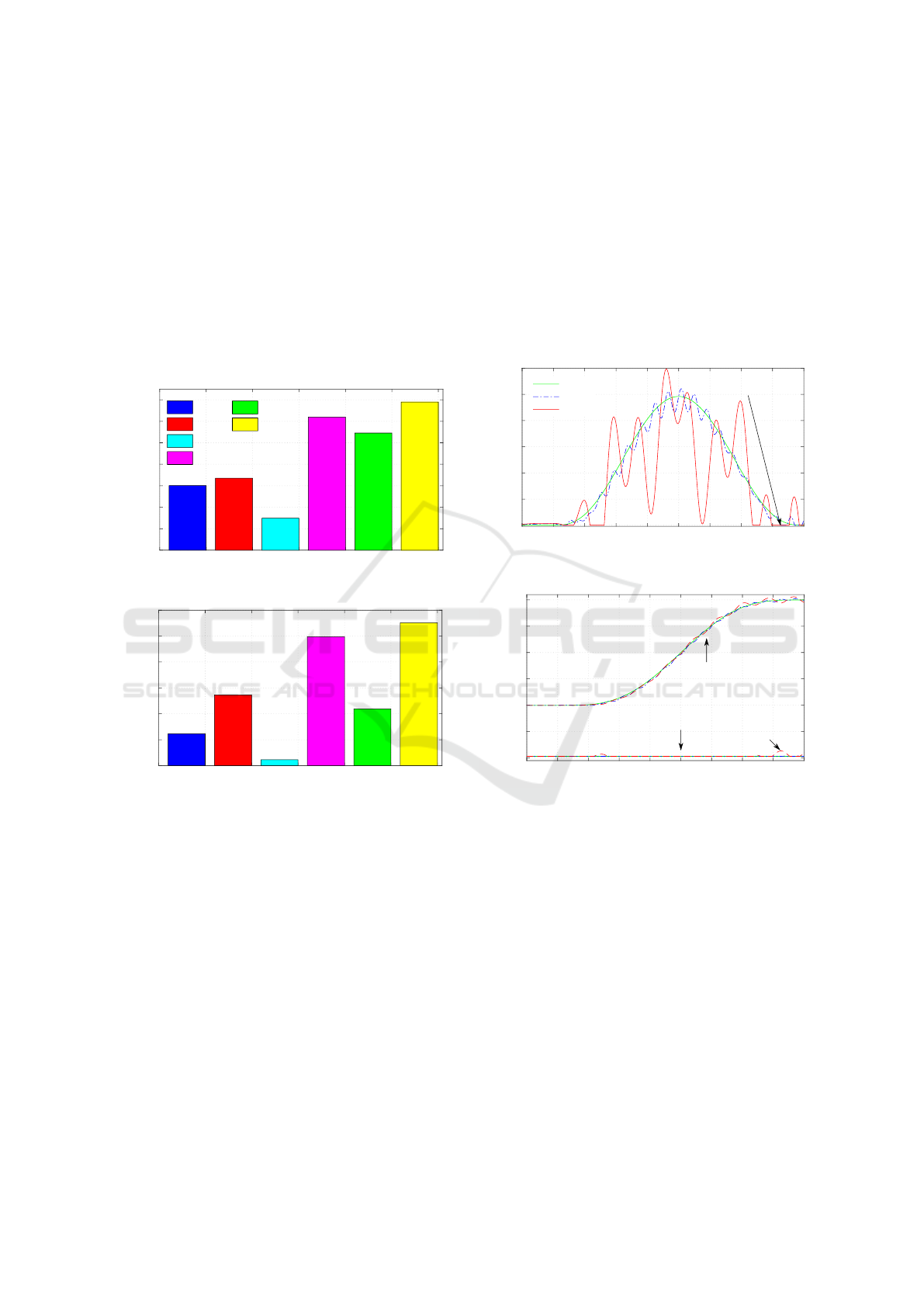
For pure position control, the controllers track a
line trajectory with low and high speed. The results
are shown in Figure 7.
0
0.1
0.2
0.3
0.4
0.5
0.6
0.7
e [mm]
rms
f
rms
r
osc
f
osc
r
max
f
max
r
(a) Tracking the line trajectory with low speed.
0
0.5
1
1.5
2
2.5
3
e [mm]
(b) Tracking the line trajectory with high speed.
Figure 7: Comparison of the end-effector trajectory track-
ing results based on the rigid (r) and flexible (f) controllers.
In these comparisons, the root-mean-squared (rms), maxi-
mum tracking error (max), and maximum oscillation am-
plitude (osc) are used as benchmarks.
Based on the simulation results of two controllers,
the flexible model based controller tracks the trajec-
tory with higher accuracy and less oscillation ampli-
tude than the rigid model based, see Figure 7 for both
tracking velocities. The difference of controllers per-
formances is increased when the end-effector tracks a
trajectory with high speed in Figure 7b. Also, the re-
sults show the end-effector position controller based
on the flexible model can track a trajectory with less
than 1% normalized root mean square error.
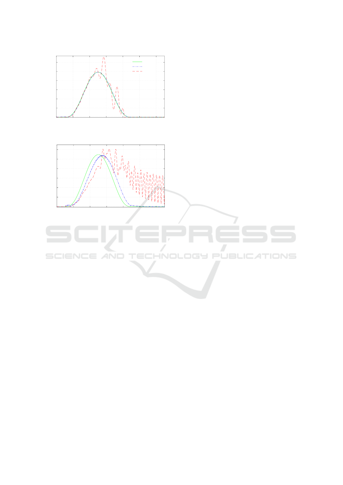
To validate the hybrid force/position controller,
in a first scenario, the robot interacts with a known
flat surface during high speed moving. The spring
stiffness for this scenario, in Equations (15) is k =
100 N/m. Figure 8 shows interaction results, e.g.,
tracking the surface and the acting force on the sur-
face by the robot contact tool.
For interacting with a known flat environment, the
maximum normalized root mean square error of the
flexible based impedance controller for moving in the
desired position and regulating acting force on the
surface are used as benchmarks and these are 1% and
5%, respectively, see Figures 8b and 8a.
0 0.5 1 1.5 2 2.5 3 3.5 4 4.5
time [s]
f
act
[N]
0
0.5
1
1.5
2
2.5
3
desired
flexible
rigid
no acting force
(a) Acting force on a known surface in fast movement.
0 0.5 1 1.5 2 2.5 3 3.5 4
4.5
time [s]
ee
c
[m]
-.60
-.55
-.50
-.45
-.40
-.35
-.30
x-direction
no contact
y-direction
(b) Contact part position on a known surface in fast move-
ment.
Figure 8: Comparison of the robot’s interaction with a
known surface. Flexible presents nonlinear controller based
on the flexible model and rigid shows the result of the con-
troller based on the rigid model.
These results show that the hybrid force/position
controller is able to apply the force at the desired po-
sition with high accuracy.
As the next scenario, a more difficult and chal-
lenging task is investigated where the robot is in-
teracting with an unknown environment. The used
spring for impedance modeling for the contact tool, in
Equations (17) has same value as in the known case.
Figure 9 shows the robot manipulation results. In con-
trast of the known case, the controller goal is related
to the acting force regulation during moving on a flat
Hybrid Force/Position Control of a Very Flexible Parallel Robot Manipulator in Contact with an Environment
65
0 1 2 3 4 5 6
0
0.5
1
1.5
2
2.5
3
time [s]
f
act
[N]
desired
flexible
rigid
(a) Acting force on an unknown surface in fast movement.
0 1 2 3 4
5
6
0
2
4
6
8
10
12
time [s]
v [cm/s]
(b) End-effector tracking velocity on an unknown surface
in fast moving.
Figure 9: Comparison the robot interaction with an un-
known surface. Flexible presents nonlinear controller based
on the flexible model and rigid show result of the controller
based on the rigid model.
surface.
For interacting with an unknown environment, the
moving with desired velocity and regulating the act-
ing force on the surface are investigated. The results
show the flexible model based controller achieved
drastically better performance than the rigid model
based. Also, the interaction results show that the flex-
ible controller can move on an unknown surface dur-
ing force regulating with more than 99% accuracy and
at minimum 88% for tracking moving velocity.
The performance of the force/position controller
in each interaction scenario shows that the flexible
model based controller reaches their desired goals
successfully and overcome to the challenges.
6 CONCLUSIONS
In this paper, a high performance end-effector posi-
tion controller and its combination with an impedance
controller are presented for a flexible parallel robot
manipulator to interact with an environment. The de-
signed position controller based on the independent
system coordinates computes the robot’s input using
the measurable states of the system, the obtained, and
the desired position and velocity of the end-effector.
The nonlinear feedback controller is extended with
an impedance part in order to regulate the contact
force, too. The simulation results on the lambda robot
model show that the nonlinear controllers based on
the flexible model have drastically better performance
than the rigid model based controllers. Also, the
hybrid force/position controller did all complicated
tasks with high accuracy and successfully overcame
to all challenges, too.
For future work, the designed controllers, i.e., the
position and impedance controller will be tested on
the real robot and their performance will be investi-
gated.
ACKNOWLEDGEMENTS
This research presented in the Cluster of Excellence
in Simulation Technology SimTech at the University
of Stuttgart and is partially funded by the Landes-
graduierten kolleg Baden-W
¨
urttembergs. The authors
appreciate these discussions.
REFERENCES
Ansarieshlaghi, F. and Eberhard, P. (2017). Design of a
nonlinear observer for a very flexible parallel robot.
In Proceedings of the 7th GACM Colloquium on
Computational Mechanics for Young Scientists from
Academia and Industry, Stuttgart, Germany.
Ansarieshlaghi, F. and Eberhard, P. (2018a). Experimen-
tal study on a nonlinear observer application for a
very flexible parallel robot. International Journal
of Dynamics and Control, doi:10.1007/s40435-018−
0467-2.
Ansarieshlaghi, F. and Eberhard, P. (2018b). Trajectory
tracking control of a very flexible robot using a feed-
back linearization controller and a nonlinear observer.
In Proceedings of 22nd CISM IFToMM Symposium
on Robot Design, Dynamics and Control, Rennes,
France.
Burkhardt, M., Holzwarth, P., and Seifried, R. (2013a). In-
version based trajectory tracking control for a parallel
kinematic manipulator with flexible links. In Proceed-
ings of the 11
th
International Conference on Vibration
Problems, Lisbon, Portugal.
Burkhardt, M., Seifried, R., and Eberhard, P. (2013b). As-
pects of symbolic formulations in flexible multibody
systems. Journal of Computational and Nonlinear
Dynamics, 9(4):041013–1–041013–8.
Burkhardt, M., Seifried, R., and Eberhard, P. (2014). Exper-
imental studies of control concepts for a parallel ma-
ICINCO 2019 - 16th International Conference on Informatics in Control, Automation and Robotics
66

nipulator with flexible links. In Proceedings of the 3
rd
Joint International Conference on Multibody System
Dynamics and the 7
th
Asian Conference on Multibody
Dynamics, Busan, Korea.
Eberhard, P. and Ansarieshlaghi, F. (2019). Nonlinear posi-
tion control of a very flexible parallel robot manip-
ulator. In Proceedings ECCOMAS Thematic Con-
ference on Multibody Dynamics, Duisburg, Germany
(accepted for publication).
Endo, T., Sasaki, M., Matsuno, F., and Jia, Y. (2017).
Contact-force control of a flexible timoshenko arm in
rigid/soft environment. IEEE Transactions on Auto-
matic Control, 62(5):2546–2553.
Feliu-Talegon, D., Feliu-Batlle, V., Tejado, I., Vinagre,
B. M., and HosseinNia, S. H. (2019). Stable force
control and contact transition of a single link flexible
robot using a fractional-order controller. ISA transac-
tions.
Hogan, N. (1985). Impedance control: An approach to ma-
nipulation: Part II–Implementation. Journal of Dy-
namic Systems, Measurement, and Control, 107(1):8–
16.
Jung, S., Hsia, T. C., and Bonitz, R. G. (2004). Force track-
ing impedance control of robot manipulators under
unknown environment. IEEE Transactions on Con-
trol Systems Technology, 12(3):474–483.
Kamikawa, Y., Enayati, N., and Okamura, A. M. (2018).
Magnified force sensory substitution for telemanipu-
lation via force-controlled skin deformation. In IEEE
International Conference on Robotics and Automation
(ICRA), pages 1–9, Brisbane, Australia.
Khalil, H. K. (2002). Nonlinear systems, volume 3. Prentice
hall, Upper Saddle River.
Li, Y., Ganesh, G., Jarrass
´
e, N., Haddadin, S., Albu-
Schaeffer, A., and Burdet, E. (2018). Force,
impedance, and trajectory learning for contact tool-
ing and haptic identification. IEEE Transactions on
Robotics, 34(5):1170–1182.
Luh, J., Fisher, W., and Paul, R. (1983). Joint torque con-
trol by a direct feedback for industrial robots. IEEE
Transactions on Automatic Control, 28(2):153–161.
Morlock, M., Burkhardt, M., Schr
¨
ock, C., and Seifried,
R. (2017). Nonlinear state estimation for trajectory
tracking of a flexible parallel manipulator. IFAC-
PapersOnLine, 50(1):3449–3454.
Morlock, M., Burkhardt, M., and Seifried, R. (2016).
Control of vibrations for a parallel manipulator
with flexible links - concepts and experimental re-
sults. In MOVIC & RASD, International Conference,
Southampton, England.
Sandoval, J., Su, H., Vieyres, P., Poisson, G., Ferrigno,
G., and Momi, E. D. (2018). Collaborative frame-
work for robot-assisted minimally invasive surgery us-
ing a 7-dof anthropomorphic robot. Robotics and Au-
tonomous Systems, 106:95–106.
Schindlbeck, C. and Haddadin, S. (2015). Unified passivity-
based cartesian force/impedance control for rigid and
flexible joint robots via task-energy tanks. In IEEE
international conference on robotics and automation
(ICRA), pages 440–447, Seattle, Washington. IEEE.
Seifried, R., Burkhardt, M., and Held, A. (2011). Trajec-
tory control of flexible manipulators using model in-
version. In Proceedings of the ECCOMAS Thematic
Conference on Multibody Dynamics, Brussels, Bel-
gium.
Siciliano, B. and Khatib, O., editors (2016). Springer Hand-
book of Robotics. Springer Heidelberg.
Siciliano, B. and Villani, L. (1999). Robot Force Control.
Springer Science & Business Media.
Suarez, A., Giordano, A. M., Kondak, K., Heredia, G., and
Ollero, A. (2018). Flexible link long reach manipu-
lator with lightweight dual arm: Soft-collision detec-
tion, reaction, and obstacle localization. In IEEE In-
ternational Conference on Soft Robotics (RoboSoft),
pages 406–411. IEEE.
Vogel, J., Haddadin, S., Jarosiewicz, B., Simeral, J. D.,
Bacher, D., Hochberg, L. R., Donoghue, J. P., and
van der Smagt, P. (2015). An assistive decision-and-
control architecture for force-sensitive hand–arm sys-
tems driven by human–machine interfaces. The In-
ternational Journal of Robotics Research, 34(6):763–
780.
Hybrid Force/Position Control of a Very Flexible Parallel Robot Manipulator in Contact with an Environment
67
