
Optimum Design and FEA of a Hybrid Parallel-deployable
Structure-based 3-DOF Multi-gripper Translational Robot for Field
Pot Seedlings Transplanting
Samy F. M. Assal
1,2 a
and Isaac Ndawula
1
1
Department of Mechatronics and Robotics Engineering,
Egypt – Japan University of Science and Technology (EJUST), Egypt
2
On leave: Department of Production Engineering and Mechanical Design,
Faculty of Engineering, Tanta University, Egypt
Keywords: Transplanting Robot, Multi-gripper, Optimum Design, Pot Seedlings Transplanting, Hybrid
Parallel-Deployable Structure.
Abstract: Pot seedlings transplanting is an activity in the agricultural production industry. In its manual level, it is a
time consuming, labour intensive, costly activity with low transplanting rate, uneven plant distribution and
low degree of accuracy. So, in this paper, a novel partially decoupled 3-DOF multi-gripper pot seedlings
transplanting robot is proposed to be used in the open agricultural field to increase the transplanting rate.
The proposed robot is composed of two identical 2-DOF Diamond Delta robots, 1-DOF scissor mechanism
and belt conveyor. Delta robot is a high speed parallel robot that is used to control the grippers in the X-Z
plane while the scissor mechanism is a deployable structure that is worked in the multi-gripper and used to
control the grippers in Y direction. Different kinematic and design aspects are considered; namely, the
kinematic analysis and the optimum design as well as the finite element analysis in the most critical loading
configuration are carried out. A unified frame work for the optimum dimensional synthesis for a prescribed
workspace with force transmission and singularity avoidance constraints is developed for the optimal
dimensions of the design parameters. The proposed robot is shown to have high transplanting rate and is
safe in terms of stress and deformation.
a
https://orcid.org/0000-0002-7997-4363
1 INTRODUCTION
Transplanting is a crucial agricultural activity which
involves the transfer of seedlings from their raising
medium to the growing medium which is either in an
open field or prepared beds under a greenhouse. It is
carried out from the high dense trays to low dense
ones in green house or to low dense distribution in
the open agriculture field. The seedlings are
classified as bare-root, plug and pot seedlings.
Vegetable seedling transplanting, the pot seedling
one, is one of major activities in vegetable
production. It is still in the manual level featured as
a time consuming, labour intensive, costly and
inefficient task. Robotic transplanting as a special
transplanting mechanization method is a remedy for
such problems. Four types of robotic and automated
transplanters have been developed for such
agriculture activity in literature; namely, robotic arm
type, door frame type, automated transplanters for
greenhouse and automated transplanters for open
field in which walk behind type transplanter
undergoes. Since the former type has been
developed mostly in green house, it leaves the open
field robotic transplanting problems unsolved.
Different robotic arm type transplanters have
been developed for greenhouse. For instance, a 5-
DOF robotic manipulator for transplanting pot
pepper seedlings was developed in greenhouse
(Hwang et al, 1986). It consisted of a gripper, pot-
type mechanical planter and 8-bit microcomputer. It
picks the seedling, transfers it and drops it in a
guided hole of the mechanical planter. One seedling
is fetched per transplanting cycle and a transplanting
rate of 6 plants/min was recorded. A feasibility study
68
Assal, S. and Ndawula, I.
Optimum Design and FEA of a Hybrid Parallel-deployable Structure-based 3-DOF Multi-gripper Translational Robot for Field Pot Seedlings Transplanting.
DOI: 10.5220/0007833500680077
In Proceedings of the 16th International Conference on Informatics in Control, Automation and Robotics (ICINCO 2019), pages 68-77
ISBN: 978-989-758-380-3
Copyright
c
2019 by SCITEPRESS – Science and Technology Publications, Lda. All rights reserved

and a simulation of using Puma 560 robot to
transplant bedding plants were performed (Kutz et
al, 1987). The robot was used to validate the model
and a transplanting productivity of 11 plants/min
was achieved with a performance of 96%. Another
feasibility study for the application of SCARA robot
in seedlings transplanting was carried out (Tmg et al,
1990). The robot was equipped with sliding needle
sensor at its gripper to ensure that each cell in the
growing tray is filled. The cyclic time of seedling
transplanting was from 2.60 to 3.25 sec and a
transplanting of 18 to 23 seedlings/min was
achieved. The performance of those serial type
manipulators is not satisfactory due to the redundant
DOF they have and their low transplanting rates. On
the other hand, the dimensional synthesis and
kinematic simulation of a 2-DOF parallel
mechanism with a pneumatic gripper for greenhouse
transplanting was studied (Hu, 2014). The
transplanting capacity was 58 seedlings/min.
Door frame type robotic transplanters for
greenhouse have been also developed. For instance,
a robotic transplanter prototype that consists of
automatic seedling feeding mechanism, a rank of
pistons, a transverse conveyor and a rotating insert
cup has been developed (Sakaue, 1996). This
transplanter can operate in both greenhouse and
open agricultural field with a productivity of 35
plants/min. A bedding plants’ robotic transplanter
that composed of a robotic manipulator with two
electrical linear motors, end-effector, a conveyor and
a vision system was developed (Ryu, 2001). The
manipulator was used to move the end-effector to
the desired working position while the vision system
was used to identify empty cells and to reduce
transplanting time with a success rate of 98%. A
vegetable transplanting robot that consists of pot
moving conveyor, planting pot conveyor, cell tray
moving conveyor, transplanting device and fingers
was developed in (Kang, 2012). The transplanting
capacity of the developed robot was 2800 pots per
hour and the rate of success was 99%. The main
demerits of door frame structure robotic
transplanters are the very huge size machine, work
only in greenhouse and low transplanting rate.
Moreover, automated transplanters for
greenhouse have been developed. For example,
automatic transplanter for plug seedling that
includes manipulator (a gantry-gate type arm),
conveyor system for plug tray, flowerpots and four
end-effectors was developed (Tian et al, 2010). The
cycle time for successful transplanting is from 1.5 to
2 sec/seedling, and the transplanting productivity is
from 1800 to 2400 seedlings/hr. A fully automated
greenhouse mechanical transplanter for potted
tomato seedlings was presented (Jin et al, 2019). It is
composed of a seedling supply mechanism, a
picking mechanism composed with a gear-rod
component and an eccentric-disk parallelogram
planting part. The transplanting speed was between
60 and 90 seedlings/ min. A vegetable seedlings
automatic conveying system was design for
greenhouse application (Jin et al, 2018). It consisted
of a tank wheel, storage seedlings mechanism,
seedlings tray and hanging cup. The results showed
success rate of 97.91% for taking an individual
seedling.
Furthermore, rather than developing automated
transplanters for greenhouse, a swing seedling pick
up device for automatic precise field transplanter
was designed and tested in field (Han et al, 1015). It
consisted of an oscillating guide linkage mechanism
and globoidal cam mechanism and two grippers. The
transplanting productivity was 70 seedlings/min. An
intelligent transplanting system for pot seedlings in
field was design and implemented (Xin et al, 2018).
It consisted of fixed-axis gear train and five bar as
picking mechanism, conveying system, eccentric
disc as planting mechanism, electric sensor for
detection and identification of missing and
unhealthy seedlings, the position sensor, the control
system and stepper motors. The system was tested
and the productivity was found to be 90 plants/min.
Also, automated walk behind type transplanters have
been developed for open field. Three models of
riding type automated vegetable transplanters were
developed (Tsuga, 2000). These prototypes consisted
of 2 rows transplanting mechanism working
simultaneously at productive frequency of 60
plants/row/min. A fully automated walk behind type
hand tractor powered vegetable transplanter for
paper pot seedlings was developed (Kumar and
Raheman, 2011). It consisted of two sets of feeding
conveyor, metering conveyor, seedling drop tube,
furrower opener, soil covering device, an automatic
feeding mechanism, a depth adjustment wheel and
hitching arrangement. The transplanting rate was 32
seedlings/min with an efficiency of 85%. A two-row
vegetable automated transplanter for transplanting
pot seedlings in the field was developed (Dihingia et
al, 2018). The transplanter was hitched to the walk-
behind hand controlled tractor as the main source of
power. The transplanting productivity of this
transplanter was evaluated in the field and found to
be 31 seedlings/min.
Form the aforementioned literature; it is
considerably to highlight that, the introduced
transplanters have low transplanting rate due to large
Optimum Design and FEA of a Hybrid Parallel-deployable Structure-based 3-DOF Multi-gripper Translational Robot for Field Pot
Seedlings Transplanting
69
cyclic time of the transplanting as well as the plant-
by-plant manner of carrying out the transplanting
task; specifically, the transplanting of one seedling
at a time. So, in this paper, as an extension of our
work (Ndawula et al, 2018), a row-by-row pot
seedling transplanter robot with low cyclic time is
proposed to achieve high transplanting rate. It has
multi grippers with 3-DOF translational motion. Its
structure permits seedlings transplanting from high
dense seedlings in a tray to low dense, equally
spaced seedlings in the open agriculture field.
The rest of the paper is organized as follows. The
description of the components of the proposed
transplanter robot and its working principle are
presented in Section 2. The kinematics, differential
kinematics, singularity and workspace analyses are
discussed in Section 3. The optimal dimensional
synthesis is developed in Section 4. The finite
element analysis (FEA) of the robot in the most
critical loading condition is carried out in Section 5.
Simulation results are presented in Section 6.
Finally, conclusion is drawn in Section 7
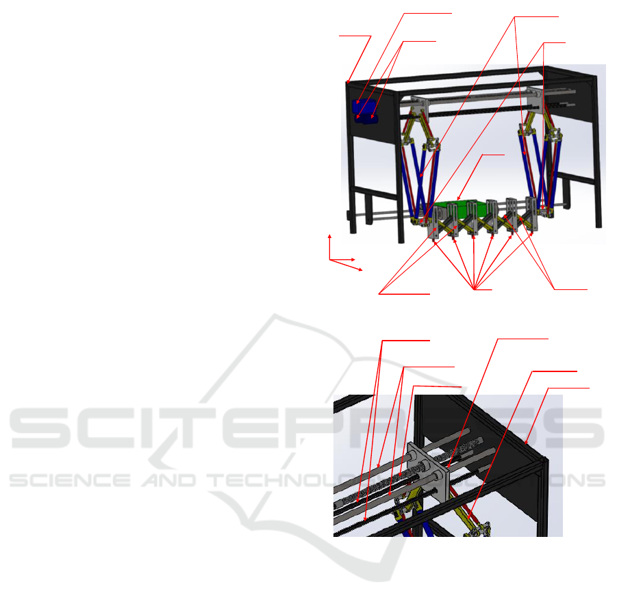
2 DEVICE STRUCTURE AND
WORKING PRINCIPLE
2.1 Device Structure
The proposed 3-DOF translational robot for row-by-
row pot seedlings transplanting in the open
agriculture field consists of three main parts as
shown in Fig. 1. Two of which are two identical 2-
DOF Diamond Delta robots positioned in two apart
X-Z planes with respect to a fixed frame. Basically,
the Diamond Delta is a 2-DOF translational planar
parallel robot with fixed and moving platforms
connected by two limbs. Each limb is composed of
active and passive links. The moving platform of
Delta robot is called end-effector. The two fixed
platforms of those two Delta robots are assembled in
the fixed frame of the proposed device such that they
can counter translate in Y-direction using two guide
way shafts that are used to ensure the smooth
translational motion. A half-length right and half-
length left hand ball screw (bidirectional ball screw),
powered by a third servo motor, is used to translate
those two symmetrically placed Delta robots in Y
direction to come close or apart from each other
depending on the desired motion. This ball screw is
meshed with two nuts fixed to the two translating
platforms of those Delta robots. The active links that
are actively connected to the translating platforms of
Fixed frame
Two Delta robots
Two servomotors to
drive Delta robots
End-effectors
of Delta robots
Two sets of
multi-scissor
Multi-bracket
frames
Multi-gripper
to be fixed
Z
Y
X
Belt
conveyer
Servomotor to Drive
the ball screw
(a) Main components of the proposed transplanter.
Spline shafts
Guide way shafts
ball Screw
Fixed Frame
Diamond Delta robot
Translating base of
Delta robot
(b) Top right magnified portion.
Figure 1: The proposed 3-DOF translational robotic
transplanter.
those Delta robots are connected by two spline
shafts which are coupled to two servo motors
mounted at the top of the fixed frame as illustrated
in Fig. 1. Those two spline shafts are used to
mechanically synchronize the motions of the two
end-effectors of the two Delta robots.
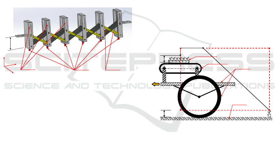
The third part of the proposed device consists of
1-DOF double planar foldable scissor mechanisms,
which works in the multi-gripper, positioned in two
apart Y-Z planes shown in Fig. 2. Basically, the
scissor mechanism is a deployable structure with 1
DOF. The ends of the scissor mechanisms are fixed
to the moving end-effectors of the two identical
planar Delta robots to work as multi grippers. Those
double planar foldable scissor mechanisms are
connected together by multi-rectangular frames with
ICINCO 2019 - 16th International Conference on Informatics in Control, Automation and Robotics
70
revolute joints and sliding grooves as shown by the
3D SolidWorks model in Fig. 2. The rectangular
frames are used to keep fixed orientation of the
grippers and thus restrict any orientation of the
seedling grippers in any direction. This scissor
mechanism keeps equal spacing between the
grippers from unfolded configuration to the folded
one. Thus, it allows suitable spacing in the picking
up and transplanting of the seedlings. Therefore, this
scissor mechanism allows row-by-row pot seedlings
transplanting as many as grippers. For instance, for
the standard 6×12 tray, the proposed robot can
equipped with 6 grippers Therefore, the grippers
have decoupled 3-DOF translational motion;
namely, 2-DOF translational motion in X-Z plane
accomplished by the parallel robots (Diamond Delta
robots) and 1-DOF translational motion in Y-
direction achieved by the scissor mechanism, the
deployable one.
Two sets of
multi-scissor
Multi-bracket
frames
Grippers
to be fixed
Z
Y
X
G
1
G
2
G
3
G
4
G
5
G
6
H
Figure 2: Two identical sets of foldable multi-scissor with
multi-bracket frame.
A pot seedlings belt conveyor is another part of
the device as illustrated in Fig. 1. This belt conveyor
is used to carry pot seedlings tray to the appropriate
position for picking up. The multi-gripper end-
effector picks up pot seedlings from growing tray,
holds, transfers and releases them at the time of
transplanting. The proposed robot that is carried
over a wheeled frame is hitched to a tractor as a
source of power and its speed is synchronized with
transplanting frequency of the robot.
2.2 Working Principle
The pot seedlings transplanting cycle in the field by
the proposed robot occurs in three stages namely;
fetching, transplanting and returning phases. The
robot starts from its initial position P
0
, then follows
the path P
0
-P
1
-P
2
in X-Z plane while closing
gripper's spacing in Y-direction to suite the seedlings
spacing on the nursery tray during seedlings
fetching, as depicted in Fig. 3. At P
2
, it picks 6
seedlings in a row of the tray at once by the 6
grippers and holds them. In the transplanting phase,
the robot follows the path P
2
-P
1
-P
0
-P
3
while opening
the scissor mechanism in Y-direction to suite the
planting space in the open agriculture field. At P
3
, it
releases the seedlings and drops them by gravity in
the vertical orientation that is achieved by the multi-
bracket frames. Then, in the returning phase, it
returns to its original position P
0
following the path
P
0
-P
3
. This cyclic process is repeated over and over
again until the operation is done. The belt conveyor
ensures the steady supply of pot seedlings at the
appropriate picking up position and the tractor
controls column spacing of the seedlings through
synchronization of motion between the tractor and
proposed robot. Note that, six furrows can be opened
in the agriculture field by 6 teeth shovel type furrow
opener while covering the seedlings with sufficient
soil and pressing the soil around the seedlings can be
done by six pairs of press wheels tilted outside at the
top, which is out of scope. The furrow opening as
well as covering and pressing the soil around the
seedlings should be synchronized with transplanting
process.
P
0
P
1
, W
1
P
2
P
3
,
W
3
Seedlings
Belt conveyer
Wheeled carrier
frame
Agriculture
field ground
Hitched
to
tractor
W
4
W
2
H
H
Figure 3: Seedlings transplanting cycle.
3 KINEMATIC ANALYSES
The main components of the proposed robotic
transplanter to be kinematically analysed are the two
2-DOF planar Diamond Delta robots. Delta robot is
a well-known positioning planar parallel
manipulator that consists of a base frame and a
moving frame (end-effector) as shown in Fig. 4.
Those two frames are connected together by two
mirror symmetrical kinematic chains. Each
kinematic chain consists of two parallelograms
which represent the proximal and distal links that are
connected by revolute joints. The proximal link is
activated by servo motor that is fixed to the fixed
frame of the device through the spline shaft, while
Optimum Design and FEA of a Hybrid Parallel-deployable Structure-based 3-DOF Multi-gripper Translational Robot for Field Pot
Seedlings Transplanting
71
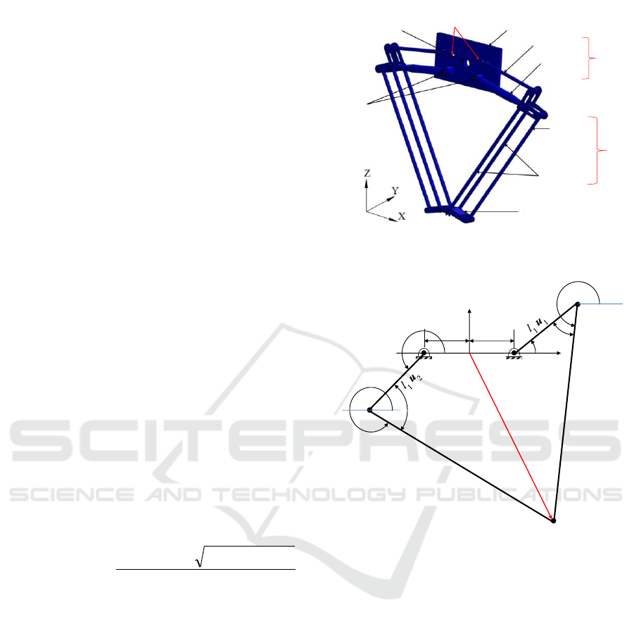
the distal link is passive. Due to the equivalence of
length of the inner and outer links of each
parallelogram, Delta robot can be simplified as a 5-
bar mechanism as illustrated in Fig. 4(b). The
inverse kinematic of this Delta robot is of interest
since it is required for the positioning control and the
trajectory planning.
3.1 Inverse Kinematics
The inverse kinematics of Delta robot is to obtain
the joint angle variables
i1
for i=1, 2 for the given
end-effector position P(x, z). For this sake, the loop
closure equation of the two closed loop kinematic
chains depicted in Fig. 4(b) are given as follows:
iii
lle wuep
21
for i=1, 2 (1)
where
T
zxp
is the position vector of the
end-effector; e
i
is a unit vector directed from O to O
i
while 2e is the centre distance between the two
spline shafts that connected the active links to the
two servo motors; l
1
is the proximal (active) link
length while u
i
is a unit vector directed from O
i
to A
i
given as
T
11
sincos
iii
u
, l
2
is the distal
(passive) link length, while w
i
is a unit vector
directed from A
i
to P given as
T
22
sincos
iii
w
. From (1), the active joint
angle variables can be obtained in terms of the end-
effector position as follows (Huang et al, 2004).
ii
iiii
i
MN
MNLiL
222
1
)sgn(
arctan2
for i=1, 2 (2)
where
zlL
ii
2
,
eixlM
ii
)sgn(2
and
xeillezxN
i
)sgn(2
2
2
2
1
222
, in
which sgn(i)=1 for i=1, otherwise sgn(i)=-1
3.2 Differential Kinematics
Differentiating the loop closure equation (1) with
respect to time yields velocity relation as the
following
iiii
QlQl wuv
2211
for i=1, 2 (3)
Inner proximal
link
Outer proximal
link
Inner distal
link
Outer distal
link
Distal
link l
2
Proximal
link l
1
Moving Frame
(end-effector)
Translating
base frame
Guide way shafts
to be fixed
Spline shafts
to be fixed
Ball screw
nut
(a) SolidWork model
O
1
O
2
O
θ
11
θ
21
θ
12
θ
22
P (x,z)
l
2
w
1
l
2
w
2
p
X
Z
β
1
β
2
e
e
A
1
A
2
(b) 5-bar simplified model of Delta robot
Figure 4: The 2-DOF planar Diamond Delta robot in X-Z
plane.
where
T
zxv
is the Delta robot end-effector
linear velocity vector in the X-Z Cartesian space,
01
10
Q
is a skew symmetric matrix. Pre-
multiplying (3) by
T
i
w
, the passive joint angles
velocities
i2
for i=1, 2 can be eliminated and the
result can be written in a matrix form as follows
1112
JlJ v
(4)
ICINCO 2019 - 16th International Conference on Informatics in Control, Automation and Robotics
72

where J
1
and J
2
are the direct and inverse Jacobian
matrices, respectively given as follows:
2
T
2
1
T
1
1
0
0
uw
uw
Q
Q
J
(5)
T
212
wwJ
(6)
On the other side, the linear velocities of the
grippers in the Y direction are related to the angular
velocity of the ball screw. For instance, the linear
velocities of gripper G
1
and G
6
shown in Fig. 2 are
given as follows:
2
61
GG
s
L
vv
(7)
where L
s
and
are the lead of the ball screw and
its angular velocity. Also, the linear velocities in Y
direction of the other grippers based on the time
derivatives of the point displacements on the
deployable scissor mechanism can be obtained as
G1GG
53
52
vvv
and
G1GG
51
43
vvv
.
3.3 Singularity Analysis and
Transmission Angle
The singularity analysis is a critical issue in parallel
robots since the robot loses its controllability in
singular configurations. To carry out such analysis,
the singularity of Jacobian matrices must be studied.
The direct kinematic singularity (second type)
occurs whenever
0=
1
J
while inverse kinematic
singularity (first type) occurs whenever
0=
2
J
The third type of singularity which is the combined
singularity occurs whenever
0=
1
J
and
0=
2
J
.
Examining those Jacobian matrices reveals that
when
i
w
is along or coincident with
i
u
for i=1, 2,
direct kinematic singularities take place, while when
1
w
coincides with
2
w
, inverse kinematic
singularities occur.
It is considerably to note that, for Delta robot,
the direct kinematic singularity is related to the
transmission angle
i
for i=1, 2 shown in Fig. 4(b).
Namely, four singular configurations occur for
i
equals to zero or π for i=1, 2. From the geometry of
Fig. 4(b), the force transmission angle
i
can be
obtained as follows
22
2
2
1
21
)sgn(
2
1
arccos zxeill
ll
i
for i=1, 2 (8)
In order to have high force transmission, the
transmission angle
min
where
35
and
),min(
min2min1min
β
(Huang et al, 2004).
3.4 Workspace Analysis
Two different types of workspaces are considered
here, the achievable workspace and the objective
one. The achievable workspace is based on the Delta
robot construction while the objective workspace is
based on the required transplanting task.
3.4.1 Achievable Workspace
The achievable workspace of the translational Delta
robot in the X-Z plane is defined as the region in this
space that can be reached by its end-effector. Carful
inspection of the inverse kinematic solution (2)
reveals that, the condition
0
i
F
for i=1, 2, should
be hold in order to have real solution, where
2
2
2
1
22
4 llZlZF
iiii
for i=1, 2 (9)
in which
xeillezxZ
i
)sgn(2
2
2
2
1
222
(10)
It can be proven that, (9) represents the equation of
two concentric circles in X-Z plane, which
represents the boundary of the achievable workspace
as shown in Fig. 5.
3.4.2 Objective Workspace
Based on the transplanting cycle discussed above,
the end-effector path during this cycle can be
described as P
0
-P
1
-P
2
-P
1
-P
0
-P
3
-P
0
from which the
regular objective workspace can be considered as a
rectangle with vertices of
),(W
iii
zx
for i=1,..,4 as
shown in Fig. 3. From the ergonomics point of view,
the vertices W
1
(-40,-60), W
2
(-40,-115), W
3
(50, -
115) and W
4
(50, -60) in cm shown in Fig. 3 are
Optimum Design and FEA of a Hybrid Parallel-deployable Structure-based 3-DOF Multi-gripper Translational Robot for Field Pot
Seedlings Transplanting
73
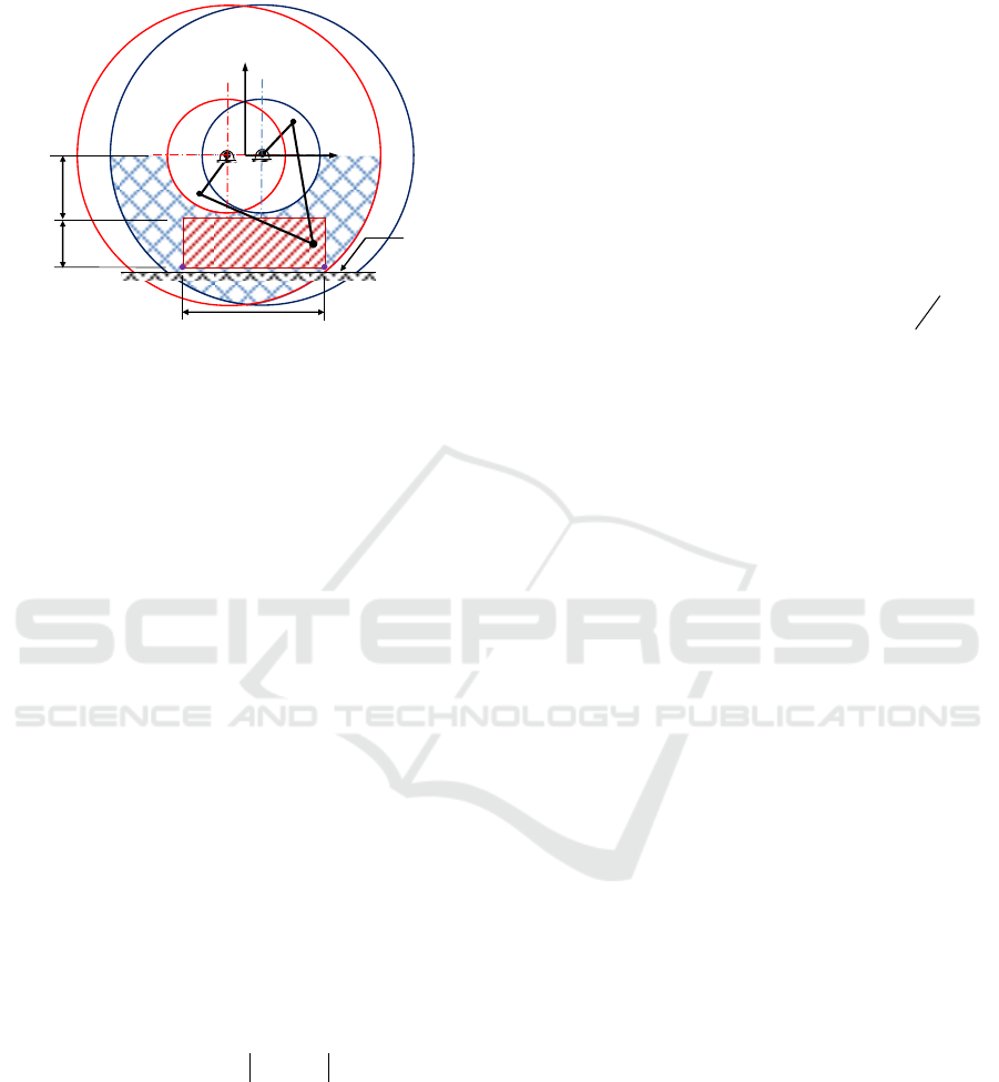
considered. Figure 5 illustrates the overlapped of the
objective workspace and the achievable workspace.
Achievable
workspace
O
X
Z
Objective
workspace
Agriculture
field ground
b
h
K
Figure 5: The achievable and the objective workspaces.
4 OPTIMAL DIMENSIONAL
SYNTHESIS
The optimal dimensional synthesis is applied here
for the Delta robot to obtain the optimal dimensions
of its design parameters. Different objective
functions either local or global for parallel
manipulators are proposed in literature (Huang, T.,
et al 2004; Assal, S. F. M., 2017). Here, since the
objective workspace of the proposed device is a
specific workspace of a rectangle with known
vertices, then the optimal dimensional synthesis is
carried out here based on satisfying a prescribed
workspace.
The objective function is a function that
describes the achievable workspace that includes the
objective workspace. Since the achievable
workspace is given in (10) as
0
i
F
for i=1, 2,
while the objective workspace is given by vertices
points
),(W
jjj
zx
for j=1,…,4, then the objective
function based on the power of point method [Laribi,
M.A., et al 2007] is given as follows
4
1
2
1
,
j i
jif
PWFO
(11)
in which
ellP ,,
21
is the design parameters
space.
Additionally, some kinematic constraints should
be achieved; namely, high force transmission and
avoiding forward kinematic singularities should be
satisfied. In order to have high force transmission,
then
min
where
),min(
min2min1min
.
From (8) this condition is equivalent to
0 cos2C
21
2
2
2
11
2
K- llll
(12)
On the other hand, the forward kinematic
singularities avoidance that is related to the force
transmission angle can be achieved as
max
where
),max(
max2max1max
. Carful inspection
of (8) reveals that this condition is equivalent to the
following condition
0
2
cos2C
2
21
2
2
2
12
b
e-hK- llll
2
(13)
Furthermore, in order to have enough space for
mounting the two servo motors, the following
constraint should be hold
0cm10
3
eC
(14)
In summary, the optimal dimensional synthesis is
optimize the function O
f
(P) subjected to the
constraints (12-14) to obtain the optimal
ellP ,,
21
. The genetic algorithm (GA)
toolbox of MATLAB is used to solve such
optimization problem.
5 FINITE ELEMENT ANALYSIS
The finite element analysis (FEA) is used to carry
out structural analysis. Structural analysis is the
measure of how physical structure of a device and its
components resist the deformation under certain
loading conditions. The FEA of the proposed robot
is carried out using ANSYS 17.2 version to
investigate the effect of applied loads on the
proposed robot at its worst case loading
configuration. The configuration at which the
proposed robot inserts its grippers into the growing
tray to pick up the seedlings is the worst load
configuration. This configuration takes place during
the fetching phase and exactly at point P
2
. At this
configuration, the inserting force per each gripper is
14 N, while the picking up force is 1 N per seedling
(Kang et al, 2012). The obtained results from this
analysis are then assessed to verify the suitability
and the safety of the proposed robotic structure for
the application. The steps for performing structural
ICINCO 2019 - 16th International Conference on Informatics in Control, Automation and Robotics
74
analysis using ANSYS for the proposed robot are
described as follows.
First, the Solid Works model of the proposed
transplanter is exported into ANSYS Workbench.
After having the proposed transplanter geometry
defined, the Aluminium alloy material is selected
and assigned to all parts of the multi-gripper scissor
mechanism and the links of the two Diamond Delta
robots, while Steel material is assigned to the rest of
the components as illustrated in Table 1. The contact
joints are assigned as well at this stage.
The adaptive meshing of the virtual prototype is
then carried out. So, several trials are performed to
improve the accuracy of the final results. After
several trials, a mesh size of 10 mm is chosen and
used. This meshing size gives better meshed
structure with less computational time and cost than
those of the values greater than or below 10 mm.
The number of nodes and elements generated in this
case are 643830 and 356630, respectively.
After the adaptive meshing, the boundary
conditions are then applied. Namely, the
bidirectional ball screw and sliders are fixed at both
ends. Furthermore, a constant insertion force of 14 N
in positive Z-direction is assigned to each of the 6
grippers that fixed at the scissor mechanism for the
worst case loading configuration.
After applying the boundary conditions and
loads, the deformations in X, Y, and Z- directions,
total deformation and Von Mises Stress analyses are
carried out.
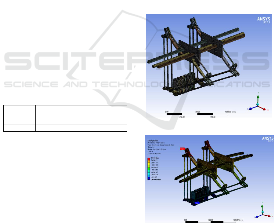
Table 1: Material properties.
Material
Young’s
Modulus
Poisson’s
ratio
Density
Steel
200 GPa
0.3
7850kg/m3
Aluminium
71 GPa
0.33
2700kg/m3
6 RESULTS AND DISCUSSION
The optimal dimensional synthesis stage is carried
out using the GA toolbox of MATLAB and yields
l
1
= 400 mm, l
2
= 921 mm and e= 120 mm. Based on
those link dimensions, the 3D model of the proposed
robot is developed using Solid Works to be imported
in ANSYS software for structure analysis as
described in Section 5.
The FEA of the proposed transplanter is carried
out using ANSYS at the worst case loading
configuration and the results are presented here. The
meshing of the constrained virtual prototype of the
proposed transplanter is illustrated in Fig. 6. The
deformations in X, Y and Z directions are depicted
in Figs 7, 8 and 9. It can be noted that, the maximum
deformations in X, Y and Z directions are 0.044
mm, 0.0139 mm and 0.1482 mm, respectively.
Additionally, the maximum total deformation of
0.1866 mm occurs in the middle of the scissor
mechanism as illustrated in Fig. 10, which is quite
acceptable.
Furthermore, the Von Mises stress is carried out
to check whether the proposed transplanter is safe
under the worst case loading condition. The results
of Von Mises stress is shown in Fig.11. It can be
pointed out that, the maximum Von Mises stress
occurs at the ends of bidirectional ball screw and
sliders. The maximum Von Mises stress is recorded
as 43.186 MPa. Since the maximum allowable
strength of the Aluminium alloy and the Steel
materials considered for the transplanter parts are
280 MPa and 460 MPa, respectively, then the
transplanter is shown to be safe with high factor of
safety.
Figure 6: ANSYS meshing of the proposed transplanter.
Figure 7: Deformation in X-direction.
Optimum Design and FEA of a Hybrid Parallel-deployable Structure-based 3-DOF Multi-gripper Translational Robot for Field Pot
Seedlings Transplanting
75
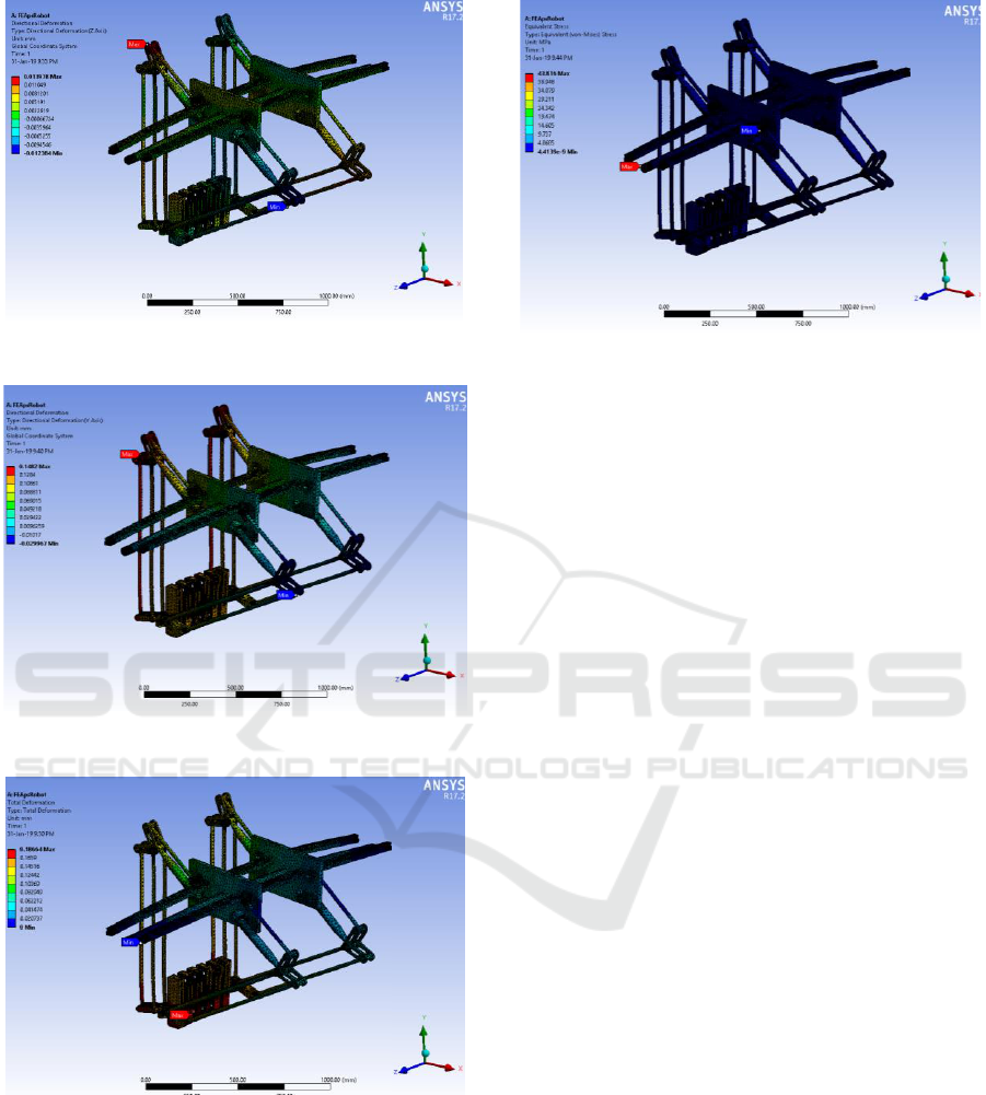
Figure 8: Deformation in Y-direction.
Figure 9: Deformation in Z-direction.
Figure 10: Total deformation.
Figure 11: Von Mises stresses.
7 CONCLUSIONS
A novel multi-gripper 3-DOF translational robot for
row-by-row pot seedlings transplanting in the open
agriculture field is introduced. It is based on hybrid
parallel-deployable structure that enables seedlings
transplanting from high dense distribution in a tray
to low dense distribution in the open agriculture
field in a row-by-row manner to increase the
transplanting rate. The optimum design as well as
the finite element analysis in the most critical
loading configuration of the proposed transplanter is
carried out. The FEA results prove that the proposed
robot is safe in terms of stresses and deformations.
Dynamic analysis and controller design as well as
prototype fabrication are the future extension of this
work.
REFERENCES
Hwang, H., Sistler, F. E., 1986. A Robotic Pepper
Transplanter, Appl. Eng. Agric., vol. 2, no. 1, pp. 2-5.
Kutz, L. J. , Miles, G. E. , Hammer, P. A. and. Krutz, G.
W, 1987. Robotic Transplanting of Bedding Plants,
Transactions of the ASAE, vol. 30, no. 3, pp. 586-590.
Tmg, K. C., Giacomelli, G. A., and Shen, S. J., 1990.
robot workcell for transplanting of seedlings part I -
layout and materials flow, Transactions of the ASAE,
vol. 33, no. 3, pp. 1005-1010.
Hu, J., Yan, X., Ma, J., Qi, C., Francis, K. and Mao, H.,
2014. Dimensional synthesis and kinematics
simulation of a high-speed plug seedling transplanting
robot, Comput. Electron. Agric., vol. 107, pp. 64-72.
Sakaue, O. 1996. Development of seeding production
robot and automated transplanter system, Japan
Agricultural Research Quarterly, vol. 30, pp. 221-226.
ICINCO 2019 - 16th International Conference on Informatics in Control, Automation and Robotics
76

Ryu, K. H., Kim, G. and Han, J. S., 2001. AE-Automation
and Emerging Technologies: Development of a
Robotic Transplanter for Bedding Plants, J. Agric.
Eng. Res., vol. 78, no. 2, pp. 141-146.
Kang, D. H., Kim, D. E, Lee, G. I, Kim, Y. H., Lee, H. J.
and Min, Y. B, 2012. Development of a Vegetable
Transplanting Robot," J. of Biosystems Eng., vol. 37,
no. 3, pp. 201-208.
Tian, S., Lichun Qiu, L., Kondo, N., Yuan, T., 2010.
Development of automatic transplanter for plug
seedling," IFAC Proceedings Volumes, vol. 43, no. 26,
pp. 79-82.
Xin, J., Kaixuan, Z., Jiangtao, J., Hao, M., Jing, P., and
Zhaomei, Q., 2019. Design and experiment of
automatic transplanting device for potted tomato
seedlings, Proceedings of the Institution of
Mechanical Engineers, Part C: Journal of Mechanical
Mechanical Engineering Science, vol. 233, no. 3, pp.
1045–1054.
Jin, X., Li, M., Li, D., Ji, J., Pang, J., Wang, J. and Peng,
L., 2018. Development of automatic conveying system
for vegetable seedlings, EURASIP Journal on
Wireless, Communications and Networking, vol.
2018:178, pages 1-9.
Han, L., Mao, H., Hu, J. and Tian, K., 2015. Development
of a doorframe-typed swinging seedling pick-up
device for automatic field transplantation, Spanish
Journal of Agricultural Research, vol. 13, no. 2,
e0210, 14 pages.
Xin, J., Kaixuan,Z., Jiangtao, J., Xinwu, D., Hao, M., and
Zhaomei, Q, 2018. Design and implementation of
Intelligent transplanting system based on photoelectric
sensor and PLC, Future Generation Computer
Systems, vol. 88, pp. 127-139.
Tsuga, K., 2000. Development of fully automatic
vegetable transplanter. JARQ, Japan Agricultural
Research Quarterly, vol. 34, no. 1, pp. 21-28.
Kumar, G. V. P. and Raheman, H., 2011. Development of
a walk-behind type hand tractor powered vegetable
transplanter for paper pot seedlings, Biosyst. Eng., vol.
110, no. 2, pp. 189-197.
Dihingia, P. C. Kumar, G. V. P. , Sarma, P. K. and Neog,
P. 2018. Hand-Fed Vegetable Transplanter for Use
with a Walk-Behind-Type Hand Tractor, International
Journal of Vegetable Science, vol. 24, no. 3, pp. 254-
273.
Ndawula, I., Assal, S. F. M., 2018. Conceptual Design and
Kinematic Analysis of a Novel Open Field 3DOF
Multi Gripper Pot Seedlings Transplanting Robot, in
Proc. of the IEEE Int. Conf. on Mechatronics and
Automation (ICMA 2018), Changchun, China, August
5-8, pp.1458–1463.
Huang, T., Li , Z., Li, M., Chetwynd, D. G., Gosselin, C.
M., 2004. Conceptual design and dimensional
synthesis of a novel 2-dof translational parallel robot
for pick-and-place operations, ASME Journal of
Mechanical Design, vol. 126, pp. 449-455.
Kang, D. H., Kim, D. E., Lee, G. I., Kim, Y. H., Lee, H. J.
and Min, Y. B., 2012. Development of a vegetable
transplanting robot, J. of Biosystems Eng., vol. 37(3),
pp. 201–208.
Assal, S. F. M., 2017. A novel planar parallel manipulator
with high orientation capability for a hybrid machine
tool: kinematics, dimensional synthesis and
performance evaluation, Robotica, vol. 35, pp. 1031–
1053.
Laribi, M.A., Romdhane, L., Zeghloul, S., 2007. Analysis
and dimensional synthesis of the DELTA robot for a
prescribed workspace, Mechanism and Machine
Theory, vol. 42, pp. 859–870.
Optimum Design and FEA of a Hybrid Parallel-deployable Structure-based 3-DOF Multi-gripper Translational Robot for Field Pot
Seedlings Transplanting
77
