
A Novel Approach for a Leg-based Stair-climbing Wheelchair based
on Electrical Linear Actuators
Emiliano Pereira, Hilario Gómez-Moreno, Cristina Alén-Cordero, Pedro Gil-Jiménez
and
Saturnino Maldonado-Bascón
Department of Theory and Signal and Communications, University of Alcalá, Spain
Keywords: Wheelchair, Leg-wheel, Stair-climbing, Architectural Barriers, Environment Adaptation.
Abstract: The objective of this work is to develop a novel low-cost wheelchair capable to climb stairs (according to
Spanish building regulation) and any obstacle similar to a step, to drive over uneven terrain such as
cobblestones and adjust the height of the seat. The contribution presented in this work can be included into
the leg-based stair-climbing mechanism classification. This work is a novel solution based on a previous
patent, which proposed a wheelchair composed of nine linear actuators controlled by a pneumatic system.
This novel approach proposes a mechanical modification in order to increase the flexibility of the mechanism,
allowing the wheelchair to move up and down without changing the orientation, also guaranteeing the
horizontal position of the user. In addition, the electric linear actuator presents some advantages with respect
to the pneumatic system proposed in the previous design, being this wheelchair easier to be controlled. This
works also presents the first prototype developed.
1 INTRODUCTION
According to a study developed by the Observatory
of Physical Disability (Fernández, 2016), 81% of
people with physical functional diversity say they
find barriers to leave their home, mainly due to the
architectural obstacles that they encounter. Although
various laws have been developed in Spain, that aim
to make public and private spaces accessible, the
limitation of these barriers supposes a very
considerable reduction in the welfare of life of people
with disabilities. Specially, people with movement
disabilities, which require the use of a wheelchair, are
affected by the presence of curbs, stairs, irregular
obstacles and the inability to easily access places that
are accessible to other users, as is the case of non-
adapted tables or countertops.
This work is focused in the mobility associated to
stairs and any obstacle similar to a step, which can be
found indoor and outdoor. The authors of this work
collaborate with a non-profitable organization
(http://padrinotecnologico.org/), whose main concern
is related with the development of devices for people
with physical disabilities, especially for children. One
of the most demanded devices is a low-cost stair-
climbing wheelchair, which can climb Spanish stairs
(Fomento, 2010) and can overpass any obstacle
similar to a step. In addition, this device must allow
the adjustment of the wheelchair height, helping the
user in different scenarios, such as the access to tables
or countertops of different heights, or the possibility
to hold conversations with other people who are
standing up. Finally, other requirement included the
wheelchair to be able to drive over uneven terrain
such as cobblestones. The authors would like to use
this prototype to apply for future CYBATHLON
races (http://www.cybathlon.ethz.ch/).
It is well known that there are several stair-
climbing assistive mechanisms for the disabled
people, see for example the thesis written by (Lawn,
2002). Research on chair-type mechanisms capable of
climbing stairs is a very active research topic
nowadays. In (Tao, 2017), the technical advantages
and disadvantages of different types of electric
powered wheelchairs with stair-climbing system are
outlined and an overall comparison of the control
method, cost of mechanical manufacture, energy
consumption and adaption to different stairs is
introduced. Table I in (Tao, 2017) presents an
excellent classification of these mechanism, where
the reader can compare the types of wheelchairs that
incorporate a stair climbing system and whether they
have been commercialized or not. According to this
Pereira, E., Gómez-Moreno, H., Alén-Cordero, C., Gil-Jiménez, P. and Maldonado-Bascón, S.
A Novel Approach for a Leg-based Stair-climbing Wheelchair based on Electrical Linear Actuators.
DOI: 10.5220/0007835202590267
In Proceedings of the 16th International Conference on Informatics in Control, Automation and Robotics (ICINCO 2019), pages 259-267
ISBN: 978-989-758-380-3
Copyright
c
2019 by SCITEPRESS – Science and Technology Publications, Lda. All rights reserved
259

reference, wheelchairs can be classified into: i) track-
based stair-climbing mechanism, ii) wheel cluster–
based stair-climbing mechanism, iii) leg-based stair-
climbing mechanism and iv) hybrid stair-climbing
mechanism.
Track-based stair-climbing mechanisms have
been successfully commercialized. These
mechanisms are based on the interlocking effect
between the track’s outer teeth and the steps’ sharp
corner. For example, TopChair-S (Heinrich, 2016) is
a good example of that. Other example based on big
wheels, which can climb stairs is the PW-4x4Q Stair
Climbing Wheelchair (Wheelchair88, 2017). These
two commercial solutions present two main
problems. The first one is that they are economically
unaffordable for families with average incomes. The
cost of these commercial solutions are around 12500
€ for PW-4x4Q and 15500 € for TopChair-S. The
second one is that they utilize the two most used
options: large wheels whose relative height can be
modified (PW-4x4Q Stair Climbing Wheelchair) and
caterpillar mechanism (TopChair-S). Performance of
these two solutions depend on the grip of the material
to the obstacle, which can be deteriorated, making the
cost of the solution even more expensive due to the
maintenance required.
The wheel cluster–based stair-climbing
mechanism is relatively compact and can easily
switch to wheeled mobile mode when running on
level ground. Examples of these mechanism are
(Quaglia, 2011) and (Quaglia, 2017), where a cluster
of three wheels is proposed. In (Quaglia, 2011), a
mechanism with only one motor and a transmission
system per locomotion unit is proposed. The
wheelchair passively changes its locomotion, from
rolling on wheels (“advancing mode”) to walking on
legs (“automatic climbing mode”), according to local
friction and dynamic conditions. In (Quaglia, 2017),
a track-based stair-climbing is combined with the
cluster of three wheels in order to improve the
wheelchair stability.
A good example of hybrid stair-climbing
mechanism is the one proposed by (Morales, 2004).
In this work, a chair model capable of climbing stairs
was presented. This mechanism has been improved in
terms of kinematic control, see for example (Morales,
2013) and (Chocoteco, 2016). This mechanism can be
adapted to different steps and obstacles, generating
smooth and comfortable trajectories for the user.
However, the mechanism is complex, which has not
made possible its commercial use to date.
Leg-based stair-climbing mechanisms can be
classified into biped and parallel mechanism. For
example, the reference (Sugahara, 2006) developed a
biped stair-climbing mechanism based on a Stewart
platform. This mechanism can walk up and down a
stair riser height of 150 mm continuously carrying 60
kg. A stair-climbing vehicle named “Zero Carrier”
with eight legs was proposed by (Yuan, 2004). In
(Wang, 2014) a concept of an eight-legged
wheelchair aiming at improving the limitations of the
Zero Carrier design was proposed. The eight legs are
grouped into two independent frames of four legs
each. The two frames can change the relative
horizontal position between them. Thus, height legs
can be substantially reduced with respect to the
design proposed in (Yuan, 2004). However, the
mechanism needed to move horizontally the frame
may be an inconvenient when heavy loads must be
carried. According to (Tao, 2017), although these leg-
based stair-climbing vehicles are complex, have high
costs, and have unconventional appearances, they are
able to achieve the core function of stair ascent and
descent and provide some innovations in climbing
wheelchair design.
The contribution presented in this work can be
included into the leg-based stair-climbing mechanism
group. This work is a novel solution based on the
patent (Kluth, 1986), which has not been built yet, nor
commercialized or referenced for other authors (up to
the authors knowledge). This original patent proposes
nine linear actuators controlled by a pneumatic
system. Eight of these actuators are used to climb the
stairs, similar to the contribution proposed in the
references (Yuan, 2004) and (Wang, 2014). In
addition, a ninth actuator is proposed to guarantee a
horizontal position of the user with a minimal of
actuators length, which is one of the problems of the
solution proposed in (Yuan, 2004). Besides this, it is
not necessary a relative displacement between each
four legs frame, which is the main problem of (Wang,
2014). The work presented also proposes a
mechanical modification of (Kluth, 1986), which
changes the configuration of the ninth actuator. This
modification increases the flexibility of the
mechanism, allowing the wheelchair to move up and
down without changing the orientation of the chair
and guaranteeing the horizontal position of the user,
as in references (Yuan, 2004) and (Wang, 2014).
Moreover, the electrical linear actuator presents some
advantages respect to the pneumatic system proposed
in (Kluth, 1986), being this wheelchair easier to be
controlled. Finally, this work shows the first
prototype developed and built in their laboratory.
This paper is organized as follows. Section 2
describes the mechanical design, paying attention to
placement of the linear actuators in order to guarantee
the climbing of standards stairs defined in (Fomento,
ICINCO 2019 - 16th International Conference on Informatics in Control, Automation and Robotics
260
2010). Section 3 presents the first low-cost prototype
developed in our research group. In this section, the
main components are also described. Finally, Section
4 discusses the conclusions and future works.
2 MECHANICAL DESIGN
The wheelchair mechanical design considers the less
favourable stairway according to (Fomento, 2010),
which is shown in Figure 1. In addition, the proposed
leg-based stair-climbing mechanism can drive over
uneven terrain such as cobblestones and adjust the
height of the chair, which can help to the user in
different scenarios, such as tables with different
heights or hold conversations with other people who
are standing up.
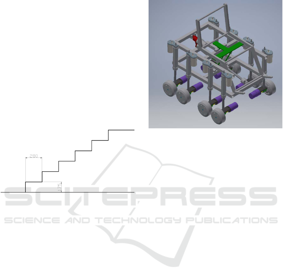
Figure 1: Most unfavourable stairway according to
(Fomento, 2010).
This section proposes: i) the wheelchair
mechanism, where all the variables to be configured
are defined, ii) the kinematic equations (direct and
inverse kinematic model), which are used in the
control of the wheelchair, and iii) the definition of the
wheelchair constant parameters according to the stair
defined in Figure 1.
2.1 Wheelchair Mechanism Description
Figure 2 shows a 3D description of the proposed
prototype made with the 3D CAD software for
product development INVENTOR (of AUTODESK).
This wheelchair has 17 electrical motors. Eight of
them are connected to one of the eight each wheels
intended to move the wheelchair. The rest of the
electrical motors are connected to linear actuators.
These linear actuators are used to change the height
of the corresponding wheel (eight of them). The last
one is used in combination with the articulated
mechanism connected to the T (green part in figure)
in order to keep the horizontal position of the chair
placed on top of it. Note that this T is fixed by two
articulated joints to the frame.
Figure 2: 3D description of the proposed prototype.
In order to better explain the mechanism, Figure
3(a) shows the left side of the wheelchair, where the
4 linear actuators connected to the left four wheels
and the linear actuator placed in its diagonal are
shown. It should be noted that the mechanical model
proposed in (Kluth, 1986), which is shown in Figure
3(b), has the actuator L
9
placed between the joints of
actuators L
2
and L
3
. The model (Kluth, 1986) cannot
guarantee the horizontal position if a step (or any
obstacle) is climbed up and down without a change in
the orientation of the mechanism. In this figure, it can
be seen:
The main constant dimensions (a, b, c, d and
r). These variables must be defined
according to the dimensions of the obstacles,
as the stair step defined in Figure 1.
Variables needed to change the leg heights
and to ensure the horizontal position of the
users (L
1
, L
2
, L
3
, L
4
and L
9
). The length of
the linear actuators L
1
, L
2
, L
3
and L
4
depend
on the relative position of each wheel with
respect to the obstacle. The length of the
linear actuator L
9
depends on the angle of the
frame respect to the horizontal reference.
The kinematic model, which is described
below, is needed in order to control this
mechanism.
The wheelchair is propelled by eight
electrical motors connected to the eight
wheels. The position control of these motors
depends on the relative horizontal position
A Novel Approach for a Leg-based Stair-climbing Wheelchair based on Electrical Linear Actuators
261
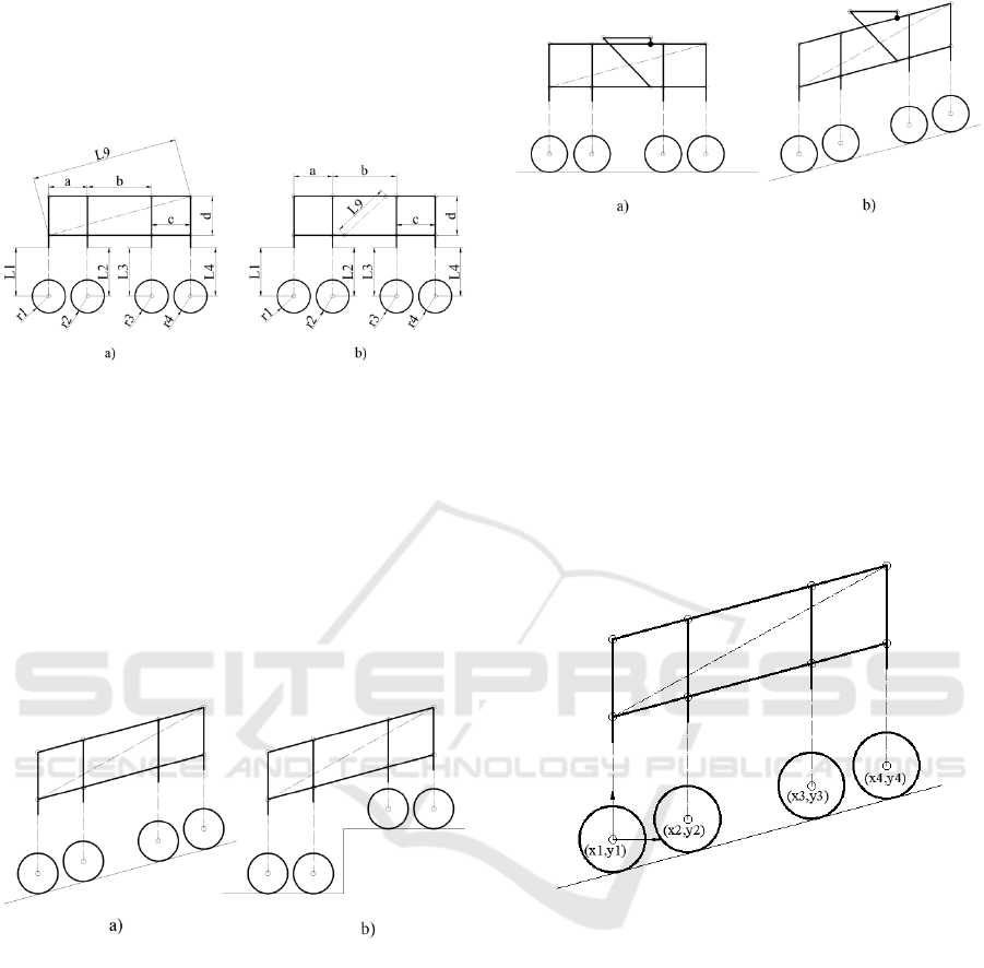
between each wheel (the full structure) and
the obstacle.
In this work the variables defined into Figure 3 are
set according to the stair profile defined into Figure 1.
Figure 3: Main structure with variables. Variables in capital
letters are calculated with the kinematic model defined
bellow. Variables in small letters must be configured
according to obstacles. (a) Wheelchair proposed in this
work. (b) Wheelchair proposes in (Kluth, 1986).
First of all, Figures 4 and 5 show illustrative
examples of how the mechanism works. Figure 4(a)
shows how the linear actuator L
9
can be configured in
order to keep constant the rest of linear actuators for
a constant slope. Figure 4(b) shows how to keep each
linear actuator perpendicular to its corresponding
step.
Figure 4: Main structure configuration for (a) slope and (b)
stair.
Figure 5 shows how the seat can be set horizontal
without any additional actuator (see green T structure
in Figure 1). Note that, the linear actuators L
1
to L
8
must be vertical (i.e., perpendicular to a horizontal
reference) in order to guarantee the horizontal
position of the chair and to reduce the strains caused
by the weight of the structure and the user.
Figure 5: Permanent horizontal platform fixed to the main
structure when (a) the wheelchair is horizontal and the (b)
the wheelchair is climbed a slope.
2.2 Direct Kinematic Model
The direct kinematic model can be deduced from
Figures 6 and 7. The objective is to relate the
Cartesian coordinate of each wheels 2, 3 and 4 respect
to the first wheel (see the values of (x
1
,y
1
), (x
2
,y
2
),
(x
3
,y
3
) and (x
4
,y
4
) in Figure 6). The reference
coordinate system is defined at the centre of the first
wheel (x
1
,y
1
).
Figure 6: Cartesian coordinates of each wheel.
As it was mentioned above, the linear actuators
L
1
-L
4
(L
5
-L
8
on the other side) must be kept vertical
in order to guarantee the horizontal position of the
chair. Thus, the rectangle of the structure (see for
example Figure 5(b)) must be changed into a
rhomboid with an angle equal to β in order to
guarantee this restriction (see Figure 7). In addition,
the angle , which depends on β, is needed to obtain
the relationship between horizontal and vertical
relative position between the origin (x1,y1) and the
centres of the other wheels: points (x
2
,y
2
), (x
3
,y
3
) and
(x
4
,y
4
).
ICINCO 2019 - 16th International Conference on Informatics in Control, Automation and Robotics
262
Figure 7: Relationship between the structure dimensions
and the angles α and β.
According to Figure 7, the angles α and β are
related as follows:
90,
(1)
where β is calculated as follows:
2
,
(2)
where L
H
is equal to a+b+c. If the variables in Figure
3 are considered, the coordinates of the centre of each
wheel is defined into Equations (3), (4) and (5) as
follows:
(3)
(4)
(5)
Note that, as it was mentioned above, if Equations
(2) and (3) are achieved, the actuators L
1
, L
2
, L
3
and
L
4
can keep a horizontal position of the chair (see
Figure 4). Note also that Equations (3), (4) and (5) are
valid also for actuators 6 (L
6
), 7 (L
7
) and 8 (L
8
),
respectively, being the origin the wheel 5. Thus, if the
objective is to climb a stair, the following restriction
must be achieved:
;
;
;
;
(6)
2.3 Definition of the Constants
Parameters (a, b, c, d and r)
An illustrative example for the stair defined in Figure
1 is presented herein. The slope of the stair defined in
Figure 1 is equal to 30º. Then, the maximum value for
must be 30º. Note that the pairs formed by wheels
1 – 2 and 3 – 4 must be placed on the same step. Thus,
the following restrictions must be achieved:
280
280
,
(7)
if the stair is climbed according to Figure 4(b). In
addition, if the prototype shown in Figure 3(a) is
considered, the following restrictions must also be
achieved:
.
(8)
This condition guarantees that the wheels have a
gap between them when the maximum value of α is
reached. For example, let us consider the wheelchair
configuration of Figure 8 and the geometry of the stair
defined in Figure 1. Note that configuration shown
Figure (8a) is useful to climb the first step with wheels
4 and 8. However, for value of α = 15º, the wheels 3
and 4 (7 and 8) cannot be placed in the same step
because the restriction defined in Equation (7) cannot
be achieved. Therefore, the value of α must be
increased. The maximum value of α, according
restriction defined into Equation (8), is 30º (see
Figure 8(b)), which is the slope of the stair defined
into Figure 1. With this value for α, the rest of steps
can be climbed.
Figure 8: Wheelchair configurations to climb the steps of
the stair defined in the Figure 1. (a) Configuration to climb
the first step. (b) Configuration to climb the rest of the steps.
2.4 Inverse Kinematic Model
The inverse kinematic model proposed in this work
consists in defining firstly an angle α suitable for
climbing the stairs. Note that the control of this angle
A Novel Approach for a Leg-based Stair-climbing Wheelchair based on Electrical Linear Actuators
263

can be obtained by implementing a feedback with the
output of a gyroscope placed on the structure. Then,
the value of β is calculated from Equation (2) as β =
α + 90. Therefore, the length of the diagonal (L
9
) is
obtained as follows:
2
cos.
(9)
Note that, if Figure 7 is considered, the value for
α can be obtained α=15º (β=105º) in Figure 8(a) and
α=30º (β=120º) in Figure 8(b). The value of L
9
can be
calculated from Equation (9).
If L
1
(L
5
) is assumed equal to zero, which
minimizes the actuator lengths, the variables L
2
(L
6
),
L
3
(L
7
) and L
4
(L
8
) can be obtained from Equations
(3), (4) and (5), respectively. These equations are:
(10)
(11)
(12)
If restrictions defined into Equations (9)-(12)
are achieved, the legs are kept perpendicular,
guarantying the configurations shown in Figure 4(b).
2.5 Electronic Control
The wheelchair prototype would be prepared to
control any actuator using an electronic control based
on Arduino (Arduino, 2019) boards for low level
control tasks and a Raspberry Pi to perform the vision
tasks needed to approach the obstacles and the
synchronization between different control boards.
There are three main control tasks. The first one is
needed to keep the seat horizontal and it is based on a
gyroscope and an Arduino micro board. The
gyroscope used will be the well-known ADXL345
that, while being low cost, is reliable and has a low
power consumption. Gyroscope, Arduino and
actuator form a classical feedback control system to
ensure that the angle α returns to 0 after a change as
shown in section 2.5. This control system is not
connected to the Raspberry since its work is
completely independent.
The second control task is the one related to the
eight electric motors connected to each wheel. In our
work, two possibilities are considered. The four
wheels on each side can be controlled in parallel
being, that way, only one motor for all practical
purposes. Then, the control is really simplified but
there is a loss of flexibility. If more flexibility is
needed, an independent motor control could be
considered. The control will be performed using
several Arduino micro boards connected to dual full-
bridge drivers L298. These Arduino boards are in
charge of the low level motion instructions while the
Raspberry Pi does the high level control after
calculations based on image processing, sensors
information (if needed) and a joystick control
operated by the user. These structure could be
simplified in a future prototype if four motors drivers
and an Arduino Mega are used.
Finally, the third control task is the needed to
climb the stairs as shown below in section 3. In this
case there are also eight motors but it is clear that each
pair in each side must be controlled at the same time.
The control in this case is also based in Arduino
boards and dual full-bridge drivers but there is no user
input and it is mainly automatic. That automatic task
will be triggered by the Raspberry Pi after the vision
system gets to the optimum position.
3 EXAMPLE OF TRAJECTORY
In this section, an example of a trajectory to climb the
stair defined in Figure 1 is explained. Figure 9 shows
the initial configuration of the wheelchair, where the
actuator lengths are defined as follows (the restriction
defined in Equation (6) is applied to all equations for
L
1
, L
2
, L
3
and L
4
):
0
.
(13)
Note that the value of α is obtained for the third
restriction (and in Figure 1 is α=15º). When x
4
>x
s0
,
the wheel 3 rise up to y
3
=y
s1
. Note that the value of α
must be increased in order to that wheels 3 and 4 can
be placed into the first step. This value for α must be
achieved before x
3
+r
3
≥x
s0
. Figure 10 shows an
example of this case, where the final actuator lengths
are calculated as follows:
0
.
(14)
Then, the height of wheel 2 must be equal to
y
s1
(y
2
=y
s1
) before x
2
+r
2
≥x
s0
. Figure 11 shows an
ICINCO 2019 - 16th International Conference on Informatics in Control, Automation and Robotics
264
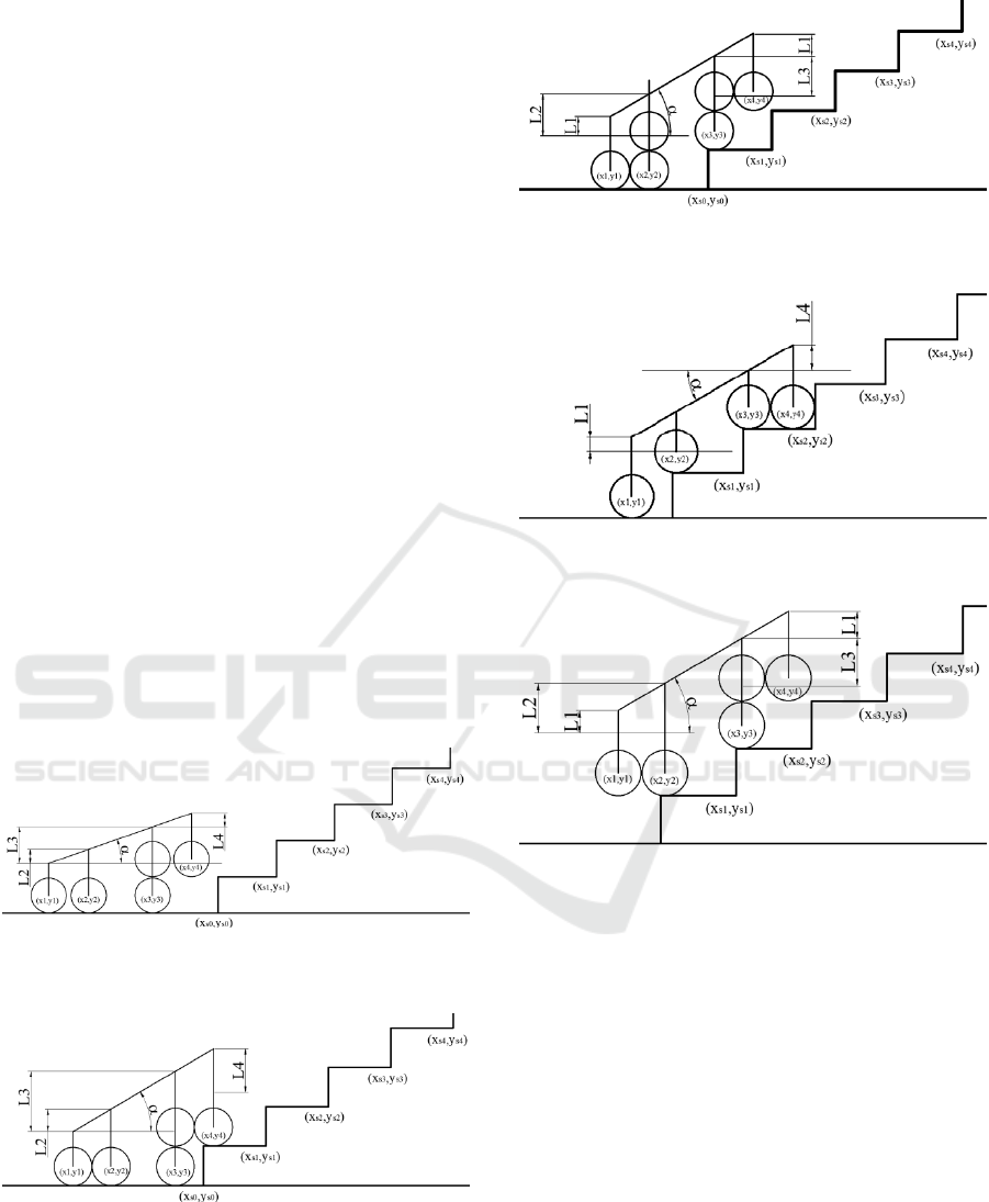
example to achieve that. The actuator lengths are as
follows:
(15)
When x
2
+r
2
≥x
s0
, the wheel 2 rises up to L
2
=0.
When x
3
+r
3
≥x
s1
, the wheel 3 rises up to L
3
=0. Figure
11 shows this configuration. The actuator length are
as follows:
0
(16)
The next restrictions are analogous to (15) and
(16) but updating the height of the steps. Figure 13
shows an example of how to climb the third step
(Figure 11 and 13 shows the same wheelchair
configuration). The optimization of the structure for a
group of stairs must be done in order to reduce the
cost of the structure and increase the speed. This is
out of this work and will be developed in future
works.
Figure 9: Initial configuration of the wheelchair when it
starts to climb the stair.
Figure 10: Example of configuration in order to climb the
first step.
Figure 11: Example of configuration in order to climb the
second step.
Figure 12: Example of configuration previous to climb the
third step.
Figure 13: Example of configuration in order to climb the
third step.
Finally, it should be noted that the final
wheelchair prototype will be based on an external
vision sensor, which will give the relative position
information between the structure and the stair (or
any obstacle). This is out of the topic of this work.
4 PROTOTYPE OF THE
WHEELCHAIR
The first prototype is designed according to the
geometrical data of Figure 8. This prototype has been
designed, developed and built in our lab, using low-
cost materials. In Figure 14, a different view of the
mechanism of Figure 2 is shown. Note that the linear
actuators and the mechanism guarantee the horizontal
A Novel Approach for a Leg-based Stair-climbing Wheelchair based on Electrical Linear Actuators
265
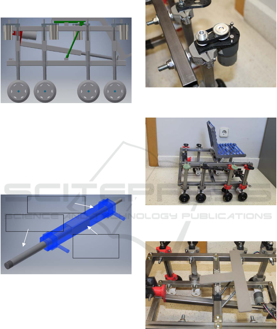
position of the user according to the kinematic model
explained above.
Figure 14: Main structure prototype.
It should be highlighted that each linear actuator
is based on a threaded bar fixed to a squared base
straight prism. When the threaded bar rotates, the
vertical position of the prism, which is connected to
the bar, changes. This threaded bar is fixed to the
support of each wheel. Details of the linear actuator
are shown in Figure 15. Each linear actuator is driven
by an electrical motor through a pulley belt
transmission system (see in Figure 16 of the built
prototype).
Figure 15: Linear actuator. Designed, developed and built
in our laboratory.
Figure 17 shows a picture of the preliminary built
prototype (1:2 scale). Note that, the chair has not been
placed yet. In addition, electrical motors and pulley
belt transmission system are not fully placed.
Figure 18 shows the details of the ninth linear
actuator and the mechanism that guarantees the
horizontal position of the users.
Figure 16: Details of the transmission between the electrical
motor and the linear actuator. 30 MXL 025 and 22 MXL
025 timing pulley and 44MXL timing belt.
Figure 17: First built prototype (1:2 scale). Main structure.
All components, except the electrical motor and the pulley
belt transmission system, have been designed, developed
and built in our laboratory.
Figure 18: First built prototype (1:2 scale). Details of the
ninth linear actuator and mechanism that guarantees the
horizontal position of the users.
threaded bar fix
squared base
straight prism
bar connected
ICINCO 2019 - 16th International Conference on Informatics in Control, Automation and Robotics
266

5 CONCLUSIONS AND FUTURE
WORKS
A novel approach for a leg-based stair-climbing
mechanism is proposed, in this work. This approach
consists of a mechanical modification of a previous
patent. This mechanical modification increases the
flexibility of the mechanism, allowing the wheelchair
to move up and down without changing the
orientation, which has not yet been implemented in
practice. In addition, electrical linear motors are used,
instead the pneumatic system proposes in the patent.
The description of the mechanism and the
kinematic equations (direct and inverse) have been
deduced. A preliminary prototype, which will be
finished by the final version of this work, has been
introduced.
Future works will consider the control system and
the external vision needed to locate the wheelchair
with respect to the obstacle. In addition, once this 1:2
scale prototype is validated, a 1:1 low cost prototype
will be built and a user test will be performed within
the facilities of the research group.
ACKNOWLEDGEMENTS
This work is supported by projects PREPEATE
(TEC2016-80326-R), of the Spanish Ministry of
Economy, Industry and Competitiveness, and
CCGP2017-EXP/030, of the University of Alcalá.
REFERENCES
Arduino Foundation, 2019, Arduino. Retrieved from:
www.arduino.cc
Chocoteco, J., Morales, R., Feliu, V., Sánchez, L., 2016,
Trajectory Planning for a Stair-Climbing Mobility
System Using Laser Distance Sensors, IEEE Systems
Journal, 10(3), 944-956.
Fernández, M., Chipre, L., Vidal, P., 2016. European
Strategy on Disability 2010-2020, Observatory of
Physical Disability, April 2016, from
https://www.observatoritercersector.org/Portals/13/
Publicacions/Llibres/2016-06_ODF_Monografic6_
English%20v2.pdf?ver=2018-02-14-101024-943.
Fomento, 2010. Documento Básico SUA, Seguridad de
utilización y accesibilidad, Ministerio de Fomento
Secretaría de Estado de Infraestructuras, Transporte y
Vivienda Dirección General de Arquitectura, Vivienda
y Suelo.
http://www.codigotecnico.org/images/stories/pdf/
seguridadUtilizacion/DccSUA.pdf
Heinrich, A, 2016, Topchair-S wheelchair has no problem
with stairs, New Atlas (https://newatlas.com/topchair-
s-stair-climbing-wheelchair/41421/)
Kluth, H., 1986. Stair Climbing Wheelchair, United States
Patent, Patent Number: 4,569,409.
Lawn, M. J., 2002. Study of stair-climbing assistive
mechanisms for the disabled, Nagasaki University,
Nagasaki City, Japan, http://citeseerx.ist.psu.edu/
viewdoc/download?doi=10.1.1.470.565&rep=rep1&ty
pe=pdf
Morales, R., Feliu, V., González, A., y Pintado, P., 2004.
Kinematic model of a new staircase climbing
wheelchair and its experimental validation, 7th
International Conference on Climbing and Walking
Robots (CLAWAR 2004).
Morales, R., Chocoteco, J., Feliu, V. y Sira-Ramirez, H.,
2013. Obstacle surpassing and posture control of a stair-
climbing robotic mechanism, Control Engineering
Practice, 21(5), 604-621.
Quaglia, G., Nisi, M., 2017. Design of a self-leveling cam
mechanism for a stair climbing wheelchair, Mechanism
and Machine Theory, 112, 84-104.
Quaglia, G., Franco, W., Oderio, R., 2011. Wheelchar.q a
motorized wheelchair with stair climbing ability,
Mechanism and Machine Theory, 46, 1601-1609.
Sugahara, Y., Hashimoto, K., Kawase, M., Ohta, A.,
Sunazuka, H., Tanaka, C., Lim, H., Takanishi, A., 2006.
Walking pattern generation of a biped walking vehicle
using a dynamic human model, In: Proceedings of the
international conference on intelligent robots and
systems.
Wang, H., He, L., Li, Q., Zhang, W., Zhang, D., Xu, P.,
2014. Research on Kind of Leg-Wheel Stair-Climbing
Wheelchair, Proceeding of 2014 IEEE International
Conference on mechatronics and Automation.
Wheelchair88 Limited (2017). PW-4x4Q Stair Climbing
Wheelchair, All terrain 4 wheel drive power chair.
Retrieved February 20, 2019, from:
https://www.wheelchair88.com/product/pw-4x4q/
Tao, W., Xu, J., Liu, T., 2017. Electric-powered wheelchair
with stair-climbing ability, International Journal of
Advanced Robotics Systems, 1-13.
Yuan, J., Hirose, S., 2004, Research on leg-wheel hybrid
stair-climbing robot, Zero Carrier, Proceedings of the
2004 IEEE International Conference on Robotics and
Biomimetics.
A Novel Approach for a Leg-based Stair-climbing Wheelchair based on Electrical Linear Actuators
267
