
Stereo Vision-based Autonomous Target Detection and Tracking on an
Omnidirectional Mobile Robot
Wei Luo
a
, Zhefei Xiao
b
, Henrik Ebel
c
and Peter Eberhard
d
Institute of Engineering and Computational Mechanics,
University of Stuttgart, Pfaffenwaldring 9, 70569 Stuttgart, Germany
Keywords:
Autonomous System, Target Detection, Target Tracking, Stereo Vision, Mobile Robot.
Abstract:
In this paper, a mobile robot equipped with an onboard computing unit and a stereo camera for autonomous
target detection and tracking is introduced. This system can figure out an interesting target and track it robustly
in real time. It is based on the ROS framework and can handle multi-resource information, such as RGB
images, depth information, and IMU data. To balance the performance of the machine learning based object
detection algorithm and the algorithm for object tracking, the Hamming distance and the intersection over
union are selected as criteria. The performance of the system is verified in a hardware experiment in two
typical scenarios.
1 INTRODUCTION
Mobile robots are among the vital investigation topics
of robotics research. Mobile robots have been widely
deployed in many applications, such as resource min-
ing (Martins et al., 2018), security patrolling (Lopez
et al., 2017), mapping (Fu et al., 2015) and object
transportation (Kume et al., 2001). To accomplish
these tasks autonomously, one of the critical chal-
lenges is to locate the robot’s target in a complex en-
vironment and to robustly track it or even estimate its
position based on information from onboard sensors.
In some of the previous works, the mobile robots are
equipped with a simple processing unit that cannot it-
self handle in real time complex sensor information
such as laser or image data. Therefore, communi-
cation between the mobile robot and a more power-
ful remote controller is necessary during operation,
which limits the practical application of the mobile
robot in the real world.
With the recent years’ rapid progress of machine
learning, object detection does not need to rely only
on predefined visual cues, such as colors (Li et al.,
2014), shapes (Gode and Khobragade, 2016) or even
templates (Kim et al., 2012), but can also be learned
a
https://orcid.org/0000-0003-4016-765X
b
https://orcid.org/0000-0002-1106-614X
c
https://orcid.org/0000-0002-2632-6960
d
https://orcid.org/0000-0003-1809-4407
from large amounts of labeled data. State-of-the-art
convolutional neural networks such as YOLO (Red-
mon and Farhadi, 2018), SSD (Liu et al., 2016) and
R-CNN (Ren et al., 2017) perform favorably in multi-
class object detection tasks with a high confidence
level, and they can be further used as a backbone for
learning new features or classes using transfer learn-
ing (Shao et al., 2015). Some works even use ma-
chine learning methods not only to detect, but also to
track the objects. However, in general, this requires
high computing power and is thereby a limitation on
the applicability on embedded systems (Chang et al.,
2018).
Different from convolutional neural network
based object detection algorithms, typical object
tracking algorithms in computer science focus on dis-
tinguishing between the target and the background.
The tracking algorithms usually run faster than the
machine learning-based algorithms, and they do not
rely on a specialized processing unit to be real-time
applicable. Several typical algorithms, such as ker-
nel correlation filter (KCF) (Henriques et al., 2015),
scalable part-based background-aware correlation fil-
ter (Fu et al., 2018) and tracking learning detection
(TLD) (Kalal et al., 2012), run extremely fast with
high tracking accuracy. Even so, these tracking al-
gorithms have their own limitations. One of them is
that they need to be provided with initial ground truth
information since they cannot self-reliantly figure out
which target they are tracking. Therefore, they require
268
Luo, W., Xiao, Z., Ebel, H. and Eberhard, P.
Stereo Vision-based Autonomous Target Detection and Tracking on an Omnidirectional Mobile Robot.
DOI: 10.5220/0007835702680275
In Proceedings of the 16th International Conference on Informatics in Control, Automation and Robotics (ICINCO 2019), pages 268-275
ISBN: 978-989-758-380-3
Copyright
c
2019 by SCITEPRESS – Science and Technology Publications, Lda. All rights reserved
an explicit identification of the initial target position
and can hardly autonomously recover once the target
is lost.
In the area of target detection and tracking, most
of the previous works focus on feature-based object
detection and tracking in the image plane (Li et al.,
2017). In this paper the approach for object detec-
tion and object tracking is modified compared to the
state-of-the-art methods and the system balances the
performance autonomously depending on the selected
criteria. Based on the detection and tracking results,
the omnidirectional mobile robot detects and tracks
the interesting target using a stereo camera and the
onboard processing unit.
The paper is organized as follows. Section 2 de-
scribes the modeling of the mobile robot, the percep-
tion and projection of the stereo camera, and the crite-
ria for the switching between tracking and detection.
In Section 3, the structure of the autonomous target
detection and tracking system and their specific prop-
erties are introduced. In Section 4, two typical scenar-
ios are set up to verify the performance of the whole
system. Finally, discussions and conclusions are pre-
sented in Section 5.
2 DEFINITION AND METHOD
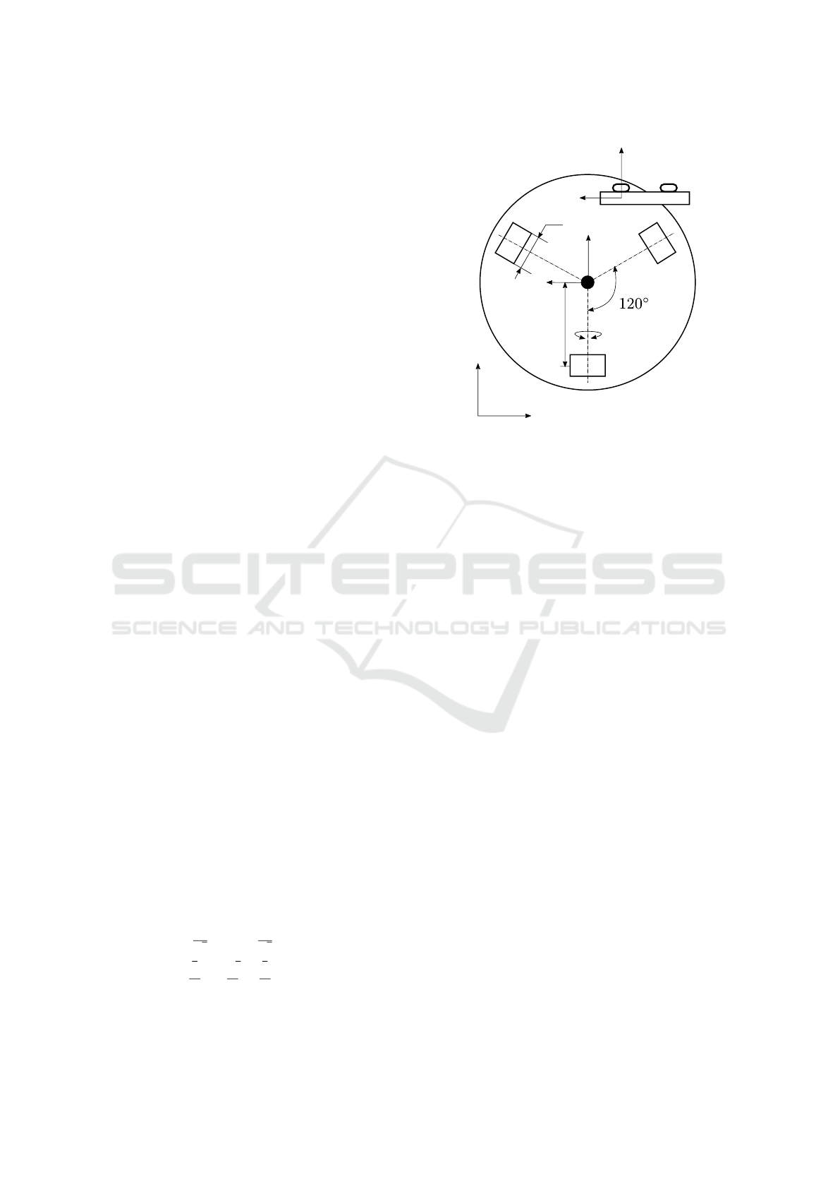
2.1 Modeling of the Omnidirectional
Mobile Robot and its Sensor System
The omnidirectional mobile robots used in this pa-
per are Robotinos from Festo. The Robotino is a
holonomic mobile robot with three omnidirectional-
directional wheels, which have angles of 120
◦
be-
tween each other, as illustrated in Fig. 1.
The subscript I indicates the inertial frame of ref-
erence. The coordinate system with subscript b is lo-
cated in the middle of the mobile robot. Meanwhile,
a stereo camera is fixed on the top of the mobile robot
with camera coordinates marked with the subscript c.
With this model, the kinematic relationship be-
tween the wheel rotation speed ω
i
and the global ve-
locity
˙
r
r
r
I
can be defined by
˙
r
r
r
I
(t) =
˙x
I
(t)
˙y
I
(t)
˙
θ
I
(t)
=
cos(θ
I
(t)) −sin(θ
I
(t)) 0
sin(θ
I
(t)) cos(θ
I
(t)) 0
0 0 1
R
w
−
1
√
3
0
1
√
3
1
3
−
2
3
1
3
1
3L
1
3L
1
3L
g
ω
1
ω
2
ω
3
,
(1)
R
w
x
c
y
c
x
b
y
b
ω
i
L
x
I
y
I
Figure 1: Robot geometry and employed coordinate sys-
tems.
where R
w
is the wheel radius, and L is the distance
between the rotation center of the Robotino and the
centers of the wheels. The angle θ
I
(t) is the rotation
angle around the z
b
-axis. The constant g := 1/16 is
the gear ratio.
Using odometry, one can obtain the position of the
robot over a particular time interval [t
k
,t
n
] by means
of
r
r
r
I
(t
n
) =
x
I
(t
k
)
y
I
(t
k
)
θ
I
(t
k
)
+
Z
t=t
n
t=t
k
˙x
I
(t)
˙y
I
(t)
˙
θ
I
(t)
dt. (2)
However, due to wheel slip and other disturbances, an
error is introduced that will be integrated over time
and it is thus expected to increase with time. There-
fore, to gain a more precise localization of the robot
in the experiment, some additional data can be fused
using a Kalman filter. One localization information
comes from an external camera with the support from
ARToolKit. To that end, on top of the robot, a pre-
defined marker is attached and its location and ori-
entation are determined relative to a marker fixed on
the ground that represents the inertial frame of refer-
ence. The second data source for data fusion can be
obtained from the inertial measurement unit (IMU) of
the ZED Mini stereo camera. This camera has a built-
in IMU which has the same coordinate system as the
left camera, seen in Fig. 1, and it can provide the ac-
celeration along the camera axes.
2.2 Perception and Projection
In this paper, a stereo camera is utilized for observ-
ing the environment and detecting the target. Com-
Stereo Vision-based Autonomous Target Detection and Tracking on an Omnidirectional Mobile Robot
269
pared with a single camera, the stereo camera does
not only provide a 2D image but also a depth image,
which can be used to estimate the 3D position of the
target (Sharma et al., 2018).
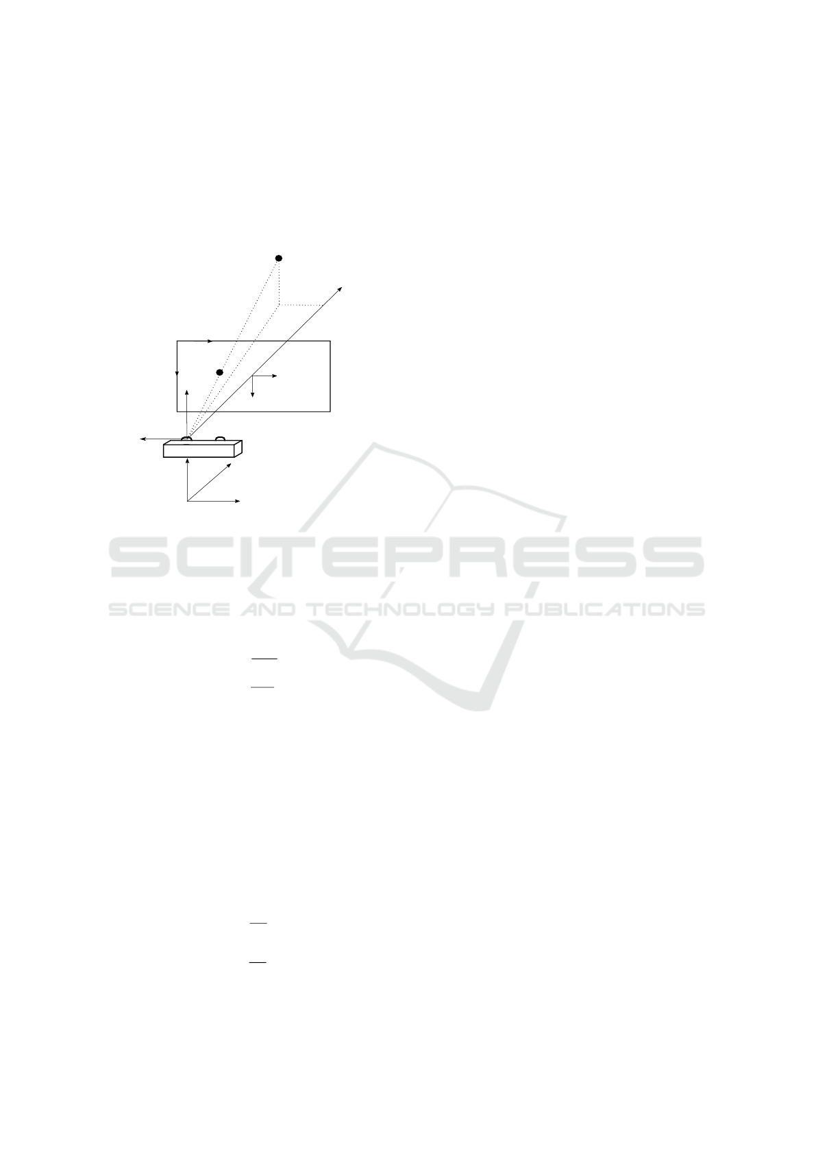
The relationship between the target position in the
inertial frame and the pixel position in the image co-
ordinate frame is illustrated in Fig. 2.
t
t
t
c
(x
t,c
,y
t,c
,z
t,c
)
t
t
t
I
(x
t,I
,y
t,I
,z
t,I
)
x
c
x
img
y
img
t
t
t
p
x
p
y
p
(w
img
,h
img
)
z
c
o
c
camera
y
c
z
I
y
I
x
I
Figure 2: Target projection in pixel-, camera- and inertial
coordinate frames.
Subsequently the applied target detection or track-
ing algorithms deliver the target’s position (u,v) in the
image frame (x
img
,y
img
) in pixel units. This pixel po-
sition can be transformed into the image coordinate
frame through the equations
x
t,p
= (u −
w
img
2
) c
P
,
y
t,p
= (v −
h
img
2
) c
P
,
(3)
yielding the target position t
t
t
p
, and where c
P
is the
pixel size by resolution and w
img
and h
img
are the
numbers of pixels in horizontal and vertical direc-
tions, respectively.
Furthermore, the stereo camera provides depth in-
formation corresponding to pixel coordinates in the
form (u,v,d). The value of d is the distance between
the object and the camera plane. Therefore, the pro-
jection of the target in camera coordinate x
c
is equal to
d. Thus, according to the triangle similarity, the target
position t
t
t
c
to the camera coordinates can be estimated
through
x
t,c
= d,
y
t,c
= −
x
t,p
f
x
t,c
,
z
t,c
= −
y
t,p
f
x
t,c
,
(4)
where f is the focal length of the stereo camera. Con-
sidering the offset and rotation between camera frame
and inertial frame, the target position t
t
t
I
in the inertial
frame can be obtained by
x
t,I
y
t,I
z
t,I
= R
R
R
Ib
R
R
R
bc
x
t,c
y
t,c
z
t,c
+ r
r
r
camera,b
+ r
r
r
m, I
(5)
in which R
R
R
Ib
is the coordinate transformation from the
mobile robot frame to inertial frame, and R
R
R
bc
denotes
the rotation matrix between the mobile robot frame
and the camera frame, which is an identity matrix ac-
cording to the coordinate system definition in Fig. 1.
Furthermore, the position of the camera frame in the
robot frame is given by r
r
r
camera,b
, while the robot po-
sition in the inertial frame is denoted by r
r
r
m,I
.
2.3 Criteria for Autonomous Switching
between Tracking and Detection
As usual, the tracking algorithms consume less com-
puting power compared with machine learning-based
object detection methods. Hence, to achieve satisfac-
tory sampling rates, it is crucial that one executes the
tracking algorithm most of the time as long as it works
properly. However, the tracking algorithm may be
mislead by other objects appearing in the view of the
camera. For instance, when an other object is mov-
ing through the image and even just briefly blocks the
target in the view of the mobile robot, or when the
target moves behind some obstacles, the tracking al-
gorithm may identify a wrong object and may never
recover. Therefore, these situations need to be auto-
matically recognized by the robot, so that it can em-
ploy an object detection algorithm to reacquaint the
target. However, the object detection algorithms have
a lower update rate than the tracking algorithms and
should hence only be executed when necessary to ob-
tain optimal performance.
To that end, it is necessary to figure out some cri-
teria to make a switching from tracking to detection
and vice versa according to the target state during the
mission. In this paper, the intersection over union and
the Hamming distance are chosen to handle this prob-
lem.
2.3.1 Intersection over Union
The intersection over union (IoU) is a typical criterion
for object detection in computer science. Usually, it
compares the estimated result with the ground truth
and returns the difference as a loss criterion. In the ap-
plication of this paper, there is no ground truth prede-
fined manually. The comparison takes place between
ICINCO 2019 - 16th International Conference on Informatics in Control, Automation and Robotics
270
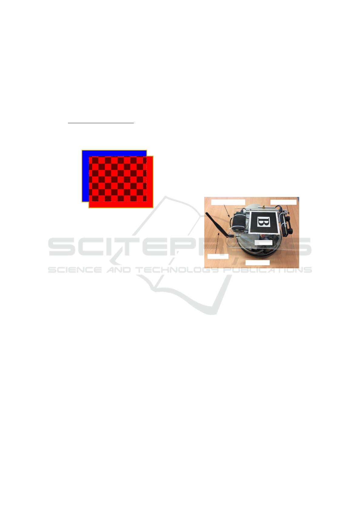
the target zone in the current image frame and the
previously estimated target zone in the image frame.
To estimate the IoU, one calculates the ratio between
the area of the intersection and the area of union of
the two target zones. The intersection area is marked
with a chess board pattern in the example illustrated
in Fig. 3. The ratio is given by using the following
equation for two target zones
IoU
i
=
target zone
i
∩target zone
i-1
target zone
i
∪target zone
i-1
, IoU
i
∈ [0,1].
(6)
target zone
i-1
target zone
i
Figure 3: The intersection and the union areas between the
image frame i and image frame i −1.
Typically, the result from Eq. 6 should be close
to 1, if the system has a high update rate, and hence,
in two subsequent images, the estimated target should
be located in a similar pixel position. When the sys-
tem tracks the wrong object, the predicted location of
the target may vary rapidly and reduce the IoU signif-
icantly. With this criterion, one can effectively detect
an unusual tracking performance and indicate to the
system to reinitialize by means of target detection.
2.3.2 Hamming Distance
Apart from calculating the position change of the tar-
get zone, the content of the zone should also be in-
spected. In this paper, the Hamming distance is used
as another criterion for judging the performance of
the system (Hamming, 1950). The Hamming distance
in this paper calculates the summation of the differ-
ence between two target images’ feature maps pixel
by pixel. If two images have a relatively large Ham-
ming distance, these two images may have recorded
different objects, which means the system has tracked
a wrong target.
To generate the feature map, the perceptual hash
(pHash) algorithm is utilized. First of all, the original
target zone is compressed into a relatively small size,
for instance 8×8 pixels, and converted from RGB to
the monochrome form. Then, the pHash algorithm
computes the features of the compressed target image
depending on the discrete cosine transform (Ahmed
et al., 1974). After gathering the image feature for
each pixel, the pHash algorithm creates an empty fea-
ture map with the same size as the compressed target
image, and then it marks the pixel with 1 in the fea-
ture map when the feature value on this pixel is above
the average of the whole image features.
3 AUTONOMOUS TARGET
DETECTION AND TRACKING
SYSTEM
3.1 Hardware Setup
In this paper, an autonomous target detection and
tracking system is built based on the omnidirectional
mobile robot Robotino, see Fig 4.
NVIDIA TX2
antenna
Robotino
marker
ZED Mini
Figure 4: Hardware setup.
In the front of the Robotino a ZED Mini stereo
camera from Stereolabs is mounted on an acrylic plat-
form. It can simultaneously provide RGB images,
depth image and point clouds at around 100 Hz, as
well as the acceleration information at up to 800 Hz.
Furthermore, an NVIDIA TX2 with a J120 carrier
board from Auvidea is attached on the acrylic plat-
form. This module has an embedded GPU unit and
can handle directly the trained neural network using
GPU-accelerated libraries. By combing the designed
hardware, the streamed data from the ZED Mini cam-
era as well as all necessary algorithms can be run in
real-time directly onboard. Additionally, a marker is
placed on top of the Robotino and the localization sys-
tem, that is based on ARToolKit, can send the robot’s
real-time position wirelessly through LCM (Huang
et al., 2010) or ROS.
3.2 System Setup
Based on the hardware above, the autonomous tar-
get detection and tracking system is deployed and or-
Stereo Vision-based Autonomous Target Detection and Tracking on an Omnidirectional Mobile Robot
271

ganized under the ROS environment. There are five
main functional blocks, and each functional block is
named ‘node’ in ROS. The whole system setup is il-
lustrated in Fig. 5.
ROS
PC
ARToolKit
localization
NVIDIA TX2
node
YOLO
ZED
target info
robot control
node
node
node
node
Robotino
(hardware)
Figure 5: System setup.
To obtain the mobile robot’s global position, an
external PC which connects a camera fixed to the ceil-
ing is required. Based on the ARToolKit, this node
calculates the Robotino’s pose using the markers in
the test field and broadcasts the robot position and ori-
entation at 10 Hz in the ROS network.
The ZED node is modified from the official ZED
ROS package. It is a hardware correlative node,
which is connected with the ZED Mini camera and
advertises the RGB images, the depth images, the
point clouds and the IMU data topics in ROS for other
nodes during the operation.
To detect the target during the operation, a ma-
chine learning framework called YOLO is utilized as
a backbone. YOLO is one of the state of art object de-
tection frameworks and it has shown its performance
for ImageNet/Coco datasets (Redmon and Farhadi,
2018). Meanwhile, it balances well the recogni-
tion speed and the prediction accuracy compared with
other object detection algorithms. These features are
essential not only for traditional object detection tasks
in computer science but also in robotics, since the
robot is sensitive to operation delays. Without loss
of generality, in the context of this paper, the tar-
get to be detected and tracked is also a Robotino.
Initially, the publicly available, pre-trained YOLO
model cannot recognize Robotinos since a Robotino
does not appear in the open dataset. Therefore, based
on the pre-trained YOLO model and newly collected
Robotino images, the modified YOLO model using
transfer learning methods is trained for the demon-
stration. The YOLO node is recomposed on the basis
of (Bjelonic, 2018). It imports the compressed RGB
image from the ZED node and determines whether
there is a target in front of the mobile robot, and then
broadcasts the target’s position in the image coordi-
nate system as well as the estimated confidence into
the ROS network.
The main component in this system is the target
info node. In this node, the necessary data are asyn-
chronously collected from the YOLO node and the
ZED node, respectively. To handle the data and ob-
tain the target information for the further process, two
threads are parallelly set up in this node. One main
thread handles the target related information and es-
timates the target position in the inertial frame. The
other thread serves as an action server and responds
to all external requests for target states.
In the main thread, a target estimation algorithm
is executed to obtain the target position in the im-
age frame, see Algorithm 1. At first, the algorithm
waits for the initial target detection from the YOLO
node, since the tracking algorithm always requires a
ground truth for the initialization. Once it gets a con-
firmation, the cropped target image will be passed
on to the tracking algorithm, where, in this paper,
the KCF algorithm is utilized as a standard track-
ing method (Henriques et al., 2015). In each loop,
the process will update the target’s features depend-
ing on the current vision from ZED node. Compared
with using only the tracking method, at the end of
each loop, the performance of the tracking method is
checked by means of the Hamming distance and the
intersection over union of the current and the last tar-
get image. If the evaluation is beyond the allowed
limits, the process will require a reinitialization for
the tracking algorithm. Since only object detection
can figure out the target from the camera image, the
process will ask the YOLO node about the target’s po-
sition depending on the YOLO result. If YOLO can
find the current target position, the process will take
the new position to reinitialize the tracking algorithm.
If both YOLO and KCF have totally lost the target,
the node marks a label to warn the other components
in system that there is no available target position cur-
rently. In the action thread, the results from the main
thread will be further processed to obtain the distance
to target and the target position in the global frame
according to the task requirement.
The last component is to control the Robotino
hardware depending on its global localization, the tar-
get states, and the depth image from the ZED node.
This node consists of two threads simultaneously. The
driving thread sends the robot’s current global local-
ICINCO 2019 - 16th International Conference on Informatics in Control, Automation and Robotics
272

Algorithm 1: Target Estimation Algorithm.
1: // Initialization
2: repeat
3: inquiring the first target confirmation;
4: until KCF is initialized
5: // Main while loop
6: while mission in process do
7: if reInit = 0 then
8: updateKCF();
9: hash
cur
= pHash(image
cur
);
10: distance = HammingDistance
(hash
cur
, hash
prev
);
11: iou result = IOU(image
cur
, image
prev
);
12: if distance or iou result over the threshold
then
13: reInit = 1;
14: else
15: hash
prev
= hash
cur
;
16: end if
17: else
18: if YOLO result available then
19: reInitKCF();
20: reInit, fail times and lost target = 0;
21: else if fail times under the limitation then
22: fail times++ and reInit = 0;
23: else
24: lost target = 1;
25: end if
26: end if
27: end while
ization to the action server into the target info node
and waits for the response. Once the target’s pixel
position and the global localization are provided, the
node connects to the Robotino using the Robotino
API and drives the robot hardware. If there is any
obstacle, detected from the depth image, in front of
the robot by the second thread, the object detection
function will lead the robot to avoid the obstacle if
necessary.
4 EXPERIMENT
To verify the performance of the autonomous target
detection and tracking system, two scenarios are set
up in the experiment. There are two Robotinos in the
field. One is the tracking robot, which is equipped
with the autonomous detection and tracking system,
the other is the target robot which moves along an ar-
bitrary trajectory during the experiment.
To test the stability of the proposed system, the
target robot follows a predefined square trajectory,
while the tracking robot should lock onto the target
robot, maintain it in the center of the view, and esti-
mate its global position in the first scenario. In Fig. 6,
four image outputs, which are recorded by the ZED
left camera from the experiment are illustrated. In
Fig. 6a, the object detection and tracking perform
similarly, therefore, the algorithm updates the target
position using the tracking algorithm. In some cases,
the object detection algorithm may not recognize the
target robot, e.g., under low light or low contrast con-
ditions, for instance, in the scene in Fig. 6b. In this sit-
uation, the system can update solely using the track-
ing algorithm. When the tracking algorithm cannot
properly track the target, as seen in Fig. 6c, the system
evaluates the performance of the tracking algorithm
and autonomously corrects the tracking result using
the detection algorithm and reinitialize the tracking
model, see Fig. 6d. Meanwhile, both the referenced
trajectory recorded by the ARToolKit and the esti-
mated trajectory target position from the system are
illustrated in Fig. 7. The performance of the position
estimation is evaluated through the root mean square
error (RMSE) through
RMSE =
r
∑
i
(x
ref,i
−x
est,i
)
2
+ (y
ref,i
−y
est,i
)
2
n
. (7)
During the experiment, the system can stably lock
onto the target robot and the RMSE of the position
estimation in the experiment is around 0.1 m.
In the second scenario, the dynamic performance
of the proposed system is verified. In this task, the
tracking robot needs to detect and follow the target
robot, while avoiding obstacles at the same time. In
the middle of the scenario, there are two obstacles that
may block the target robot from the tracking robot’s
view. Therefore, the system has the ability to re-
gain the target position and resume the tracking pro-
cedure once the target is lost. The scenario setup and
the trajectories of both robots and the estimated tar-
get are illustrated in Fig. 8. At the beginning of the
experiment, the tracking robot will turn to the target
and shorten the distance between itself and the target,
once the target is found. After a short movement, the
system detects the obstacle in the view, which may
cause a collision. Therefore, the system drives the
tracking robot away from the obstacle preferentially.
Furthermore, for testing the performance and robust-
ness of the system, the target robot moves and tries
to hide behind the obstacle, as seen in Fig. 9. If the
target is out of the camera range, e.g., the scene in
Fig. 9b, the system analyzes the feedback from the
target info node and drives the tracking robot to go to
the last estimated target position in the global coordi-
nate frame. Then, it executes a search process until
the target robot appears again in the view.
Stereo Vision-based Autonomous Target Detection and Tracking on an Omnidirectional Mobile Robot
273
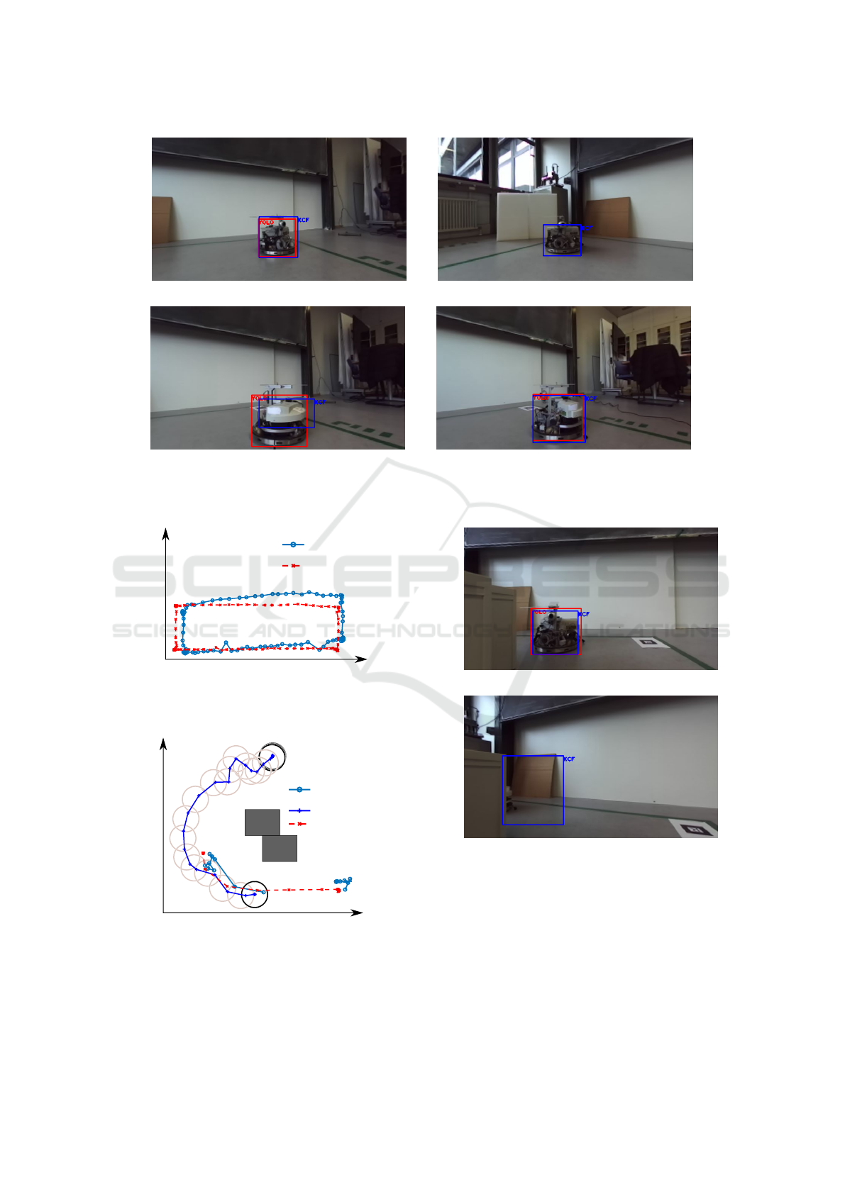
(a) Both algorithms find the target. (b) YOLO fails in detection.
(c) KCF cannot properly track the target. (d) The reinitialization is executed based on
YOLO results.
Figure 6: Four image outputs from the first scenario, as recorded by the left ZED camera.
estimated
target robot
0.0 0.5
1.0
1.5
2.0
1.6
1.2
1.0
0.8
0.6
0.4
1.4
target position
x axis [m]
y axis [m]
Figure 7: Trajectories of the estimated target position and
the real target position in the first scenario.
estimated
tracking robot
target robot
0.0 0.5
1.0
1.5
2.0
1.6
1.8
1.2
1.0
0.8
0.6
0.4
0.2
1.4
0.0
target position
x axis [m]
y axis [m]
Figure 8: Trajectories of the tracking robot, the target robot
and the estimated target robot position in the second sce-
nario.
(a) The target robot moves and hides itself.
(b) The target is beyond the view of the camera.
Figure 9: Two image outputs from the second scenario.
5 CONCLUSIONS
In this paper, an autonomous target tracking and de-
tection system is designed and implemented on an
omnidirectional mobile robot. Based on the eval-
uation of the Hamming distance and the intersec-
ICINCO 2019 - 16th International Conference on Informatics in Control, Automation and Robotics
274

tion over union, the system orchestrates the detec-
tion and tracking algorithms within the ROS environ-
ment. During the experiment, the system can guide
the tracking robot to find the target robustly in real
time. Furthermore, with the stereo vision, the system
also has the ability to estimate the target’s position
using depth information which can drive the robot to
track and get close to the target. In future work, more
criteria can be chosen and tested within the system.
Furthermore, it seems promising to train a recurrent
neural network to potentially gain a better detecting
and tracking performance.
ACKNOWLEDGEMENTS
This research benefited from the support by the China
Scholarship Council (CSC, No. 201808080061) for
Wei Luo.
REFERENCES
Ahmed, N., Natarajan, T., and Rao, K. R. (1974). Discrete
cosine transform. IEEE Transactions on Computers,
C-23(1):90–93.
Bjelonic, M. (2016–2018). YOLO ROS:
Real-time object detection for ROS.
https://github.com/leggedrobotics/darknet
ros.
Chang, Y., Chung, P., and Lin, H. (2018). Deep learning
for object identification in ROS-based mobile robots.
In IEEE International Conference on Applied System
Invention (ICASI), pages 66–69, Chiba, Japan.
Fu, C., Carrio, A., and Campoy, P. (2015). Efficient vi-
sual odometry and mapping for unmanned aerial vehi-
cle using arm-based stereo vision pre-processing sys-
tem. In International Conference on Unmanned Air-
craft Systems (ICUAS), pages 957–962, Denver, USA.
Fu, C., Zhang, Y., Duan, R., and Xie, Z. (2018). Ro-
bust scalable part-based visual tracking for UAV with
background-aware correlation filter. In IEEE Interna-
tional Conference on Robotics and Biomimetics (RO-
BIO), pages 1–8, Kuala Lumpur, Malaysia.
Gode, C. S. and Khobragade, A. S. (2016). Object detection
using color clue and shape feature. In International
Conference on Wireless Communications, Signal Pro-
cessing and Networking (WiSPNET), pages 464–468,
Chennai, India.
Hamming, R. W. (1950). Error detecting and error cor-
recting codes. The Bell System Technical Journal,
29(2):147–160.
Henriques, J. F., Caseiro, R., Martins, P., and Batista, J.
(2015). High-speed tracking with kernelized corre-
lation filters. IEEE Transactions on Pattern Analysis
and Machine Intelligence (TPAMI), 37(3):583–596.
Huang, A. S., Olson, E., and Moore, D. C. (2010).
LCM: Lightweight communications and marshalling.
In IEEE/RSJ International Conference on Intelligent
Robots and Systems (IROS), pages 4057–4062, Taipei,
Taiwan.
Kalal, Z., Mikolajczyk, K., and Matas, J. (2012). Tracking-
learning-detection. IEEE Transactions on Pat-
tern Analysis and Machine Intelligence (TPAMI),
34(7):1409–1422.
Kim, D., Lee, D., Myung, H., and Choi, H. (2012). Ob-
ject detection and tracking for autonomous under-
water robots using weighted template matching. In
Oceans - Yeosu, pages 1–5, Yeosu, South Korea.
Kume, Y., Hirata, Y., Kosuge, K., Asama, H., Kaetsu, H.,
and Kawabata, K. (2001). Decentralized control of
multiple mobile robots transporting a single object in
coordination without using force/torque sensors. In
IEEE International Conference on Robotics and Au-
tomation (ICRA), volume 3, pages 3004–3009 vol.3,
Seoul, South Korea.
Li, J., Wang, J., and Mao, J. (2014). Color moving object
detection method based on automatic color clustering.
In Proceedings of the 33rd Chinese Control Confer-
ence (CCC), pages 7232–7235, Nanjing, China.
Li, K., Zhao, X., Sun, Z., and Tan, M. (2017). Robust
target detection, tracking and following for an indoor
mobile robot. In IEEE International Conference on
Robotics and Biomimetics (ROBIO), pages 593–598,
Macau, China.
Liu, W., Anguelov, D., Erhan, D., Szegedy, C., Reed, S., Fu,
C.-Y., and Berg, A. C. (2016). SSD: Single shot multi-
box detector. In Leibe, B., Matas, J., Sebe, N., and
Welling, M., editors, European Conference on Com-
puter Vision (ECCV), pages 21–37, Amsterdam, the
Netherlands.
Lopez, A., Paredes, R., Quiroz, D., Trovato, G., and Cuellar,
F. (2017). Robotman: A security robot for human-
robot interaction. In 18th International Conference on
Advanced Robotics (ICAR), pages 7–12, Hong Kong.
Martins, A., Almeida, J., Almeida, C., Dias, A., Dias, N.,
Aaltonen, J., Heininen, A., Koskinen, K. T., Rossi, C.,
Dominguez, S., V
¨
or
¨
os, C., Henley, S., McLoughlin,
M., van Moerkerk, H., Tweedie, J., Bodo, B., Zaj-
zon, N., and Silva, E. (2018). UX 1 system design
- a robotic system for underwater mining exploration.
In IEEE/RSJ International Conference on Intelligent
Robots and Systems (IROS), pages 1494–1500.
Redmon, J. and Farhadi, A. (2018). Yolov3: An incremental
improvement. CoRR, arxiv.org/abs/1804.02767.
Ren, S., He, K., Girshick, R., and Sun, J. (2017). Faster
R-CNN: Towards real-time object detection with re-
gion proposal networks. IEEE Transactions on Pat-
tern Analysis and Machine Intelligence, 39(6):1137–
1149.
Shao, L., Zhu, F., and Li, X. (2015). Transfer learning for
visual categorization: A survey. IEEE Transactions on
Neural Networks and Learning Systems, 26(5):1019–
1034.
Sharma, T. G., Kritin Valivati, N., Puthige, A., and Hari,
U. (2018). Object position estimation using stereo vi-
sion. In IEEE 8th International Advance Computing
Conference (IACC), pages 66–71, Greater Noida, In-
dia.
Stereo Vision-based Autonomous Target Detection and Tracking on an Omnidirectional Mobile Robot
275
