
Reducing the Hydraulic Resistance in the Inlet Device
of the Gas Turbine Unit
Oleg Baturin, Daria Kolmakova
a
, Grigorii Popov
b
, Vasilii Zubanov
c
and Yulia Novikova
Samara National Research University, Samara, Russia
Keywords: Hydraulic Losses, Work Shaft, Gas Pumping Unit, Inlet Unit.
Abstract: The paper presents the results of numerical simulation of air flow through a modernized variant of the inlet
filter unit (IFU) of the gas compressor unit GPA-Ts-16. A feature of the IFU design is that to reduce the load
on the filter unit, it is proposed to be as compact as possible, which determines its complex shape. The goal
of the study is to study the hydraulic losses and to develop the measures to reduce them, since it is found that
every 100 Pa of losses in the inlet unit increases the consumption of fuel gas by 2.5 kg/h or reduces the engine
power by 10.5 kW. Calculations of hydraulic losses in IFU are carried out for cases of absence or presence of
wind with a velocity from 0 to 35 m/s, blowing from 5 main directions (0, 45, 90, 135, 180). Studies are
also carried out on the effect of the weather shield shape, presence of baffles under it, and the rack in the shaft
on the hydraulic losses. As a result of the research, recommendations are provided for designing (changing
the shape) of the inlet filter unit that eventually allow to propose a design that will reduce the hydraulic losses
in IFU by 15% relative to the originally suggested variant.
NOMENCLATURE
DIS – de-icing system;
FB – filter box;
GPU- gas pumping unit;
GTU – gas turbine unit;
IFU – inlet filter unit;
PJSC - Public Joint Stock Company;
SAC – Standard Atmospheric Conditions;
p – pressure drop, Pa;
T – temperature, K.
1 INTRODUCTION
The Russian Public Joint Stock Company Gazprom
today is one of the largest energy companies in the
world. Its main activities are geological exploration,
production, transportation, storage and sale of gas,
gas condensate and oil, as well as the production and
sale of electricity and heat. PJSC Gazprom provides
a
https://orcid.org/0000-0003-2806-3073
b
https://orcid.org/0000-0003-4491-1845
c
https://orcid.org/0000-0003-0737-3048
a continuous cycle of gas supply from the field to the
consumer (Gazprom, 2019; Zabelin et al., 2013).
The peculiarity of the gas industry of the Russian
Federation is that its main gas fields are located to the
east of the Urals, and gas consumers are in Europe
and China. Such a geographical location determines
the presence of a large and extensive gas transmission
system, through which natural gas is supplied from
the field to the consumer. For example, the length of
the Druzhba gas pipeline (across the territory of the
former USSR) is approximately 3,900 km, and of the
Soyuz gas pipeline is 2,750 km (Druzhba pipeline,
2019) (Figure 1). In total, PJSC Gazprom owns 161.7
thousand km of trunk pipelines included in the unified
gas supply system of Russia (Zabelin et al., 2013).
An important element of any gas transportation
system is gas pumping stations, which increase the
pressure of natural gas in the gas pipeline and give an
impulse necessary for its movement. Compressor
stations are located evenly along the entire pipeline
every 100...150 km. In 2013, PJSC Gazprom had 215
linear compressor stations, 6 gas processing
88
Baturin, O., Kolmakova, D., Popov, G., Zubanov, V. and Novikova, Y.
Reducing the Hydraulic Resistance in the Inlet Device of the Gas Turbine Unit.
DOI: 10.5220/0007836300880099
In Proceedings of the 9th International Conference on Simulation and Modeling Methodologies, Technologies and Applications (SIMULTECH 2019), pages 88-99
ISBN: 978-989-758-381-0
Copyright
c
2019 by SCITEPRESS – Science and Technology Publications, Lda. All rights reserved

complexes and 25 underground gas storage facilities,
also using compressor stations. 87.2% of compressor
stations have a gas turbine drive (about 3400 gas
turbine engines (GTE) in total) (Zabelin et al., 2013).
Among the GTUs owned by PJSC Gazprom, over
18% are NK-16ST engines (Figure 2) with a capacity
of 16 MW, developed at PJSC Kuznetsov (Zabelin et
al., 2013; JSC "Kuznetsov", 2019) in the late 1970s
based on the NK-8 aviation engine and operating as
part of GPA-Ts-16 (Figure 3).
Figure 1: Gas transportation system of Russian
(INNOVAES, 2019).
1 - Inlet guide vane; 2 - Low pressure compressor; 3 - Middle
annular frame; 4 - High pressure compressor; 5 - Combustion
chamber; 6 - High pressure turbine; 7 - Low pressure turbine;
8 - Free turbine; 9 - Free turbine bearing; 10 - Clutch.
Figure 2: Gas turbine drive of gas compressor unit NK-
16ST (RTEH GTD NK-16ST Vse o transporte gaza, 2019).
GPA-Ts-16 showed good performance and high
reliability. For this reason, a significant part of GPUs
that have been overaged is not replaced with modern
ones, but is being repaired, combining the
replacement of outdated units with modernization
aimed at reducing costs (increasing efficiency) and
eliminating deficiencies identified in operation.
During modernization, baseline unit has low level of
filtration and quickly clogs up in snowy weather.
1 - turning part of the inlet shaft; 2 - inlet sound absorber;
3 - air cleaning device; 4 - cyclic air heating system;
5 - heat recovery; 6 - exhaust sound absorbers;
7 - diffuser; 8 - exhaust support; 9 - engine compartment,
10 - oil system units
Figure 3: Gas pumping unit GPA-Ts-16 (RTEH GTD NK-
16ST Vse o transporte gaza, 2019).
2 RESEARCH OBJECT
The inlet filter unit of an industrial gas turbine is
intended for cleaning cyclic air coming from the
atmosphere to the engine inlet from dust and other
mechanical inclusions at all possible modes of
operation. IFU, despite its apparent simplicity
(compared to the engine), is an important element of
the GPU, in which complex processes take place. IFU
must reliably clean the air entering the gas turbine
unit from impurities to avoid critical damage to the
elements of the flowing part by foreign objects. In this
case, the pressure losses must be minimal to improve
the efficiency of the engine and prevent compressor
surge. The inlet unit must exclude clogging of filter
elements with snow and ice at all operating
conditions. Errors in the creation of IFU can
significantly reduce the operational properties of the
entire gas turbine station, however, this component is
usually referred to the secondary elements of the
engine and less attention is paid to its perfection than,
for example, to the compressor.
One of the companies engaged in the supply of
equipment for the GPA-Ts-16 under modernization is
LLC Volga-Energogaz, which office is in Samara
(Russia) (VolgaEnergoGaz, 2019). The engineers of
this company offered several variants of the IFU of
GPA-Ts-16 and appealed to the Department of
Aircraft Engine Theory (Department of Aircraft
Engine Theory, 2019) of the Samara National
Research University (Samara University, 2019) with a
request to evaluate the level of hydraulic losses in IFU
variants, and to help in choosing the final variant.
Reducing the Hydraulic Resistance in the Inlet Device of the Gas Turbine Unit
89
The IFU design proposed by LLC Volga-
Energogaz consists of a weather shield with an inlet
from the bottom, a filter box with two-stage Folter
cassette filters with filtration class G4/F8 (Air inlet
Filtration for GAS turbines, 2019), a diffuser, a vertical
shaft with sound absorbing panels, a turning channel,
an engine inlet duct with lemniscate and de-icing
system pipelines (Figures 4 and 9). The proposed IFU
variants differed in the shape of the weather shield
(with straight walls and roundings) and the
presence/absence of baffles in the inlet section below it
and a rounded rack in the turning channel.
The vertical shaft, the turning channel and the
engine inlet duct with lemniscate are adopted from the
existing GPA-Ts-16 mine. The remaining elements are
being developed and will be manufactured again.
The main idea of the modernization is the
replacement of the inertial filters which proved to be
unsatisfactory with the two-stage Folter cassette filter
with the filtration class G4/F8 of the square shape with
dimensions of 592x592mm. A clean filter of this type
has a hydraulic resistance of 75 Pa. The maximum
pressure drop on the contaminated filter reaches,
according to the manufacturer, 450 Pa (Air inlet
Filtration for GAS turbines, 2019). Unfortunately,
more detailed filter permeability characteristics are not
known.
Figure 4: Proposed IFU design.
The required number of filters (124 pieces) is selected
based on the nominal air flow rate through the engine
102 kg/s, considering 15% of the reserve (i.e. based
on the mass flow rate of 117 kg/s). In the baseline
variant, it is assumed that there are 4 filters along the
height of the filter box. This required to increase the
lateral area of the filter box for their placement by the
increasing complexity of its shape (Figures 4 and 5),
considering the required number of filters. In this
case, the designers seek to keep the minimum size of
the filter box to reduce the load on the shaft.
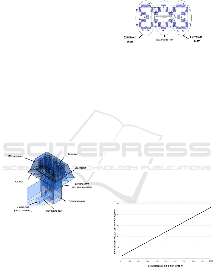
Figure 5: The adopted shape of the filter box (in plane) with
their accepted numbering.
3 THE INFLUENCE OF
HYDRAULIC LOSSES IN THE
INLET UNIT ON THE
EFFICIENCY OF THE ENGINE
GPU
At the first stage, using the thermodynamic model of
the NK-16ST engine, created and verified according
to the data provided by PJSC "Kuznetsov" (JSC
"Kuznetsov", 2019), a study of the influence of the
hydraulic perfection of the IFU of this engine on the
fuel consumption in the case of maintaining a
constant power of 16 MW (Figure 6) is conducted. A
study on the effect of hydraulic perfection of IFU on
engine power at a constant flow rate of fuel gas is also
carried out (Figure 7).
The results show that an increase in hydraulic
losses in IFU leads to a linear increase in fuel gas
consumption and a decrease in power. Every 100 Pa
of losses in the inlet unit increases the fuel gas
consumption by 2.5 kg/h or reduces the engine power
by 10.5 kW.
Figure 6: The increase in fuel gas consumption of the NK-
16ST depending on the hydraulic losses in the inlet unit
under the constant power.
SIMULTECH 2019 - 9th International Conference on Simulation and Modeling Methodologies, Technologies and Applications
90

Figure 7: Decrease in the power of the NK-16ST depending
on the hydraulic losses in the inlet unit at a constant
consumption of fuel gas.
4 DESCRIPTION OF
COMPUTATIONAL MODEL
The design model for determining the hydraulic
losses in IFU of GPA-Ts-16 is created in the NX and
Ansys CFX software in accordance with the drawings
provided by LLC Volga-Energogaz.
The computational model includes a part of the
atmosphere around the inlet shaft and a flowing part
of the IFU with an engine block simulator (Figure 8).
The modeling of the surrounding atmosphere is
necessary to correctly simulate the fields of
parameters at the inlet to the shaft, considering
changes in the direction and velocity (force) of the
wind. The engine block simulator is used to consider
the effect of gas pumping unit blocks in modeling
winds blowing from the engine side. The model
considers the full geometry of the channels, the
presence of filters, sound absorbing panels, racks in
the transition duct (if available), pressure drop in the
filter elements, ring collector of DIS, etc. The
presence of the operating floor around the perimeter
of the filters is not considered. Filters are modeled
simplified (see below).
In the numerical simulation of the working
process in the inlet shaft, the following boundary
conditions are applied:
The inlet condition is applied at the boundary of
the considered part of the atmosphere. The air
temperature (in SAC) T
a
= 288 K, the velocity
(in m/s) and the direction of the wind (as
direction cosines) are set for it. In all cases, it is
assumed that the wind blows parallel to the
surface of the earth.
The outlet boundary of the model is located at
the engine inlet. The mass flow rate through the
engine is set for it.
The surface of the earth is an impenetrable wall.
For the calculation, it is assumed that during the
"numerical experiment" the engine operational mode
(mass flow through it) and atmospheric pressure do
not change. It is also assumed that the mass flow rate
of air through the engine is identical for all considered
working conditions. In other words, the response of
the GTE control system to weather conditions is not
taken into account.
Figure 8: Computational model of the inlet shaft of the
GPA-Ts-16.
Because the exact geometry and permeability
characteristics of the filter materials are not known,
they are modeled as follows. The filter geometry is
simplified, and its shape is parallelepiped. A
condition (interface) is imposed on it according to
which the flow falling on the inlet surface 1 is
transferred to the outlet surface 2 in such a way that
the pressure on the surface 2 is less than 1 by the
amount of pressure drop in the filter Δp. Thus, in the
created computational model, total pressure losses on
the filters are considered the same in all filters (the
filters are uniformly polluted), regardless of external
conditions (wind speed and direction).
An ideal gas with air properties and variable heat
capacity and viscosity is used as a working fluid in
the simulation. When calculating, the turbulence
model k-ε with a scalable wall function is used in
calculation.
The calculation model is meshed by a finite
volume grid (Figure 9). It is based on tetrahedral
elements in combination with a prismatic layer on the
surface of streamlined walls. The total number of
final volumes is 11 million. The number of finite
volumes is selected based on the study of mesh
convergence, the results of which are shown in
Table 1. In the course of the study, 4 models were
created based on one computational model
corresponding to the initial geometry (Variant 1,
Table 2), differing in the density of the finite volume
mesh.
Reducing the Hydraulic Resistance in the Inlet Device of the Gas Turbine Unit
91

Figure 9: The grid of finite volumes of the created
computational model.
Table 1: Results of the study of the mesh convergence of
the computational model.
The number of
model elements,
mln
2
5
11
39
The drop in total
pressure in the
shaft, Pa
703
728
750
746
It is obvious from Table 1 that the global
numerical values obtained by models with a mesh of
11 and 39 million elements are close, but the
computation time in the latter case is significantly
higher. Therefore, in the future, a mesh with an
approximate number of elements of 10...12 million is
adopted for all studies (the number of elements
changed due to changes in the geometry of the shaft).
Due to the large dimension of the computational
grid, gas-dynamic modeling is carried out on the
“Sergey Korolev” supercomputer (Supercomputer
Center - Samara University, 2019). The calculations
involved 128 cores and 128 GB of RAM.
During the study, 4 variants of the inlet shaft
design (Table 2) are considered:
Variant 1 - In accordance with the drawing
provided by the Customer (Figure 11) (with
roundings and baffles at the inlet and rack in the
turning channel);
Variant 2 - Option without rounding and baffles,
but with a rack;
Variant 3 - Identical to Variant 1, but without a
rack (Figure 4);
Variant 4 - Identical to Variant 1, but without
baffles.
Table 2: Scheme of differences of the considered variants.
Variant
1
2
3
4
Rounding at the inlet of the
weather shield
+
-
+
+
Baffles at the inlet
+
-
+
-
Rack in the turning channel
+
+
-
+
All variants are considered in the absence of wind
and in the presence of winds at velocity of 10, 20 and
35 m/s from five main directions (0, 45, 90, 135,
180) (Figure 10).
To simplify the analysis of the obtained results,
the averaged values of the flow parameters and
contours of the parameters (velocity and pressure) in
the flowing part are considered in 7 control sections
along the path (Figure 11):
0 - the lower edge of the weather shield (is
absent in variant 2);
1 - lower edge of weather shield after baffles;
2 - at the inlet to the filters (box-shaped);
3 - between filter box and diffuser;
4 - in front of sound absorbing panels;
5 - after sound absorbing panels;
6 - at the GTE inlet.
Figure 10: Main wind direction.
SIMULTECH 2019 - 9th International Conference on Simulation and Modeling Methodologies, Technologies and Applications
92

Figure 11: Considered IFU control sections.
5 STUDY OF THE IFU
WORKFLOW IN CALM
WEATHER
Summarized data on the expected values of total
pressure losses in the considered IFU variants without
the wind effect (wind velocity is 0 m/s) is shown in
Figure 12. Losses are calculated as an algebraic
difference between the area-averaged values of the
total pressure in the control sections. The distribution
of total pressure losses between the section of the IFU
flowing path for the considered variants without wind
is shown in Figure 13.
It is clear from the figures that all the considered
variants show close hydraulic characteristics (total
pressure losses) in calm weather. The difference
between the four variants is no more than 30 Pa. In
calm weather, the total pressure losses vary from 380
(with clean filters) to 750 Pa (with dirty filters).
Figure 12: Total pressure losses in IFU for various
modifications of the baseline design in calm weather.
Figure 13: Total pressure losses in IFU elements for various
modifications of the baseline design in calm weather.
The total hydraulic losses in the flowing part of
IFU in calm weather for all the considered variants do
not differ and are approximately 310 Pa (excluding
losses in the filters).
As can be seen from the obtained results, the
physical picture that occurs with “clean” (Δp = 75 Pa)
and “dirty” (Δp = 450 Pa) filters is identical under the
assumptions made (uniform contamination of filters).
The difference is only a quantitative estimation of the
hydraulic losses (the computational models for
estimating losses with clean and dirty filters are
identical, except for the pressure drop at the interfaces
simulating the operation of the filter (75 Pa for clean
filter and 450 Pa for dirty filter).
For this reason, in the future, all computational
models are calculated only with “dirty” filters (Δp =
450 Pa), since this option is the ultimate in terms of
losses.
The main losses of total pressure in the shaft occur
when the working fluid passes through the filters
(section 2-3) and when the flow turns in the transition
duct and moves in the channel before entering the
engine (section 5-6). In the first two section (0-2) with
zero wind, the loss of total pressure is negligible.
Losses in the diffuser (section 3-4) and in sound
absorbing panels (section 4-5) are relatively small (do
not exceed 40 Pa) and do not depend on the shaft
design.
It should be noted that the losses in the filter box
are largely determined by the losses on the filter
element. Additional losses in this component do not
exceed 70 Pa.
The reason for the increased losses when turning
the flow in the turning channel and in the inlet channel
of the GTE is in the fact that during the flow of the
working fluid, vortex zones appear on the right and
on the left of the engine, as well as a high level of
velocity (up to 70 m/s) in the engine inlet channel.
Reducing the Hydraulic Resistance in the Inlet Device of the Gas Turbine Unit
93
The vortex in the turning channel is generated as
follows. The internal part of the filter box is divided
by baffles into three parts (two external and one
internal) (Figure 5). The air passing through the filters
of the inner part is directed vertically downward
directly to the engine inlet and is immediately sucked
into it (Figure 14). Only a small part passes by and
interacts with side vortices or falls into the space
between the lemniscate and the front wall of the
engine block.
At the same time, the air trapped in the outer parts,
passes a more complex trajectory. For example, air
passed through filter No. 6 (Figure 5) goes through all
the space of the filter box almost to filter No. 3
(Figure 14) and turns down there. The air that has
passed through the side filters No. 4, 5, 7 (Figure 5)
interacts with the flow through filter No. 6 and almost
immediately turns down. Thus, a substantial mass of
the working fluid from filters No. 4-7 moves in the
direction of the filter No. 3 (Figure 5) inside the box.
As a result, the working fluid passes through the filter
No. 3 only in the lower sections outside. From the
upper sections, the working fluid is pulled out in the
opposite direction (Figure 15). Thus, with the adopted
configuration of the filter box, not all filters work in
the same way. Filters facing the atmosphere pass the
working fluid through only in the “inward” direction.
Part of the filters located in the recesses ("pockets"),
pass the working fluid in smaller quantities, or vice
versa release it back.
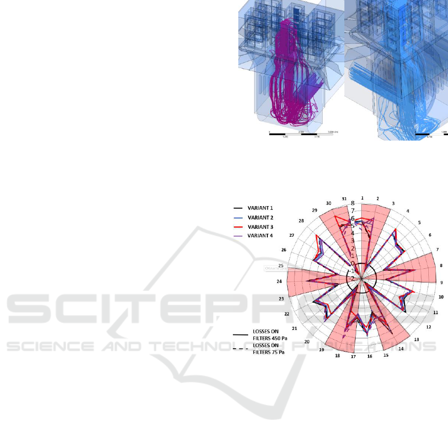
In Figure 15 and further on similar graphs (Fig. 21
and 24), a circular diagram of the distribution of air
flow between the vertical rows of filters is shown.
This graph is plotted in the polar coordinate system.
In it, along the radius, the total value of the mass flow
rate through the vertical row of filters in kg/s is
deposited. A positive sign indicates that the working
fluid flows into the filter unit, a negative one indicates
that it flows out. The angular position corresponds to
the number of the filter row according to Figure 5
(indicated on the periphery of the circle).
Figure 15 illustrates this fact, showing the
distribution of working fluid mass flow rates between
the vertical rows of filters for all 4 considered IFU
variants (excluding wind) with maximum and
minimum pressure losses on the filters. Thus, in calm
weather, 4 vertical rows of filters do not work (the
working fluid flows out of them) and another 4 rows
work with reduced flow rates.
Analysis of the flow structure (Figure 16) of the
considered IFU variants shows that in calm weather,
air enters the shaft from all directions, uniformly
filling the entire inlet section.
Central part
Side part
Figure 14: An example of the flow of air through the various
sections of the filter box.
Figure 15: The distribution of the flow rates of the working
fluid between the filters (the numbers correspond to
Figure 5) (the shaded areas correspond to the filters in the
"pockets").
If we compare the flow structure in the variants
without rounding of the weather shield walls (Variant
2) and with it (Variant4), it can be concluded that a
large flow separation is formed on the inlet edge of
the weather shield for the variant without rounding,
which reduces the effective flow area, and increases
the flow rate at the inlet to the filters. Thus, the
rounding at the inlet to the weather shield forms a
more favorable flow structure at the inlet, reducing
the velocity at the inlet and its unevenness. In general,
the rounding of the weather shield in calm weather
reduces hydraulic losses by a relatively small value.
However, in the presence of wind, the gain
significantly increases.
SIMULTECH 2019 - 9th International Conference on Simulation and Modeling Methodologies, Technologies and Applications
94
Velocity vectors
Velocity vectors
Variant 1
Variant 2
Figure 16: The flow structure in section 0 (inlet to the
weather shield) for variant 1 and 2.
6 STUDY OF THE IFU
WORKFLOW IN THE
PRESENCE OF WIND
To assess the influence of wind force and direction on
the working process and hydraulic losses of the inlet
shaft, a study is conducted in which the wind velocity
varies from 0 to 35 m/s and the direction from 0° to
180° (Figure 10).
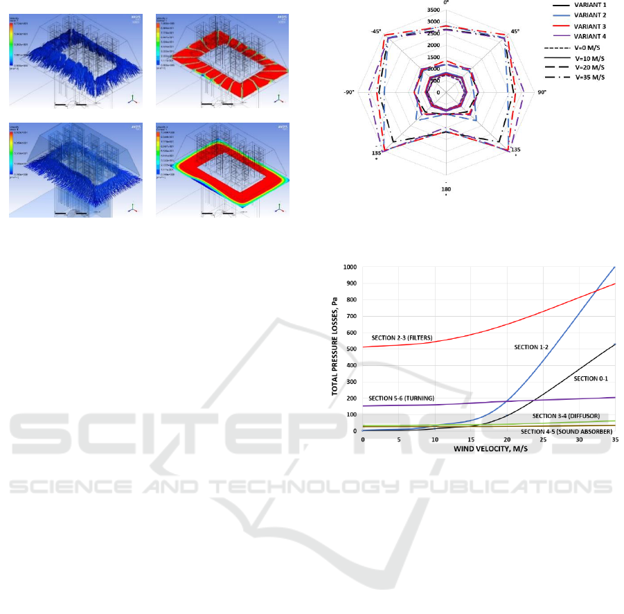
Figure 17 shows how the values of the total
pressure losses change in all the considered variants of
the inlet shaft when the force and direction of the wind
change. As can be seen, with increasing wind velocity,
the hydraulic resistance of the shaft is constantly
increasing. The increase in losses is not linear. With the
wind velocity of up to 10...15 m/s, the losses of total
pressure in the inlet shaft differ little from non-wind
conditions. A further increase in wind velocity leads to
an avalanche-like increase in losses.
In order to understand the causes of losses, the
averaged (among all the calculated variants of the
design and wind direction) total pressure loss values
in characteristic sections of the inlet shaft at various
wind velocities (Figure 18) are calculated.
The most intensive growth of losses is observed at
the inlet to the shaft (section 0-2, more than 500 times
with a change in wind speed from 0 to 35 m/s) and in
filter box (by 70%). In the turning channel (sections
5-6), the growth of losses is moderate (30%). The
greatest losses occur with side winds (45...135°). It is
curious to note that the change in wind velocity and
its force has little effect on the losses of total pressure
in the diffuser and sound absorbing panels, which
confirms the conclusion made earlier that minor
Figure 17: The dependence of the total losses of total
pressure in the inlet shaft with different force and direction
of the wind.
Figure 18: The change in the averaged values of the total
pressure losses in the characteristic sections of the inlet
shaft with increasing wind velocity.
design changes in these parts are not able to
significantly change the shaft hydraulics.
Some changes in the total pressure losses in the
turning channel (section 5-6) is associated with a
change in the flow structure there. In the presence of
wind, there is a redistribution of air flow between the
outer and inner parts of the filter box. The flow rate
of the working fluid through the windward outer part
increases, through the inner and leeward outer part -
decreases. As a result, the intensity of the vortices and
the average level of the flow velocity located on the
right and left of the engine inlet change, the flow loses
a symmetrical character, local flow accelerations
appear (including in the filter box and sound
absorber), the interaction of the vortices changes,
which increases losses.
Losses in the section before the filters are
associated with the formation of vorticity during
flowing past the weather shield inside and outside.
Figure 19 shows the trajectories of air particles before
they fall under the weather shield when the wind
direction is 45°. With other wind directions, the flow
Reducing the Hydraulic Resistance in the Inlet Device of the Gas Turbine Unit
95

structure does not change in principle. It can be seen
that the working fluid is sucked into the shaft evenly
from all directions in windless weather, but in the
presence of wind the main part of the air enters from
the narrow sector on the windward side. At the same
time, when flowing the weather shield and shaft, a
vortex structure is formed on the leeward side (Figure
19, 20).
In calm weather, all the working fluid goes into
the filters after passing section 0 along the shortest
path. Overflow under the shield is minimal. In the
presence of wind, the working fluid immediately
enters the filters only on the windward side. At the
same time, the air flow velocity increases
substantially compared to calm conditions. The
amount of working fluid that passes under the shield
from the windward side is greater than the filters can
pass through on this side, and the working fluid
begins to flow to the leeward side. This overflow,
coupled with areas of reduced pressure on the leeward
side, caused by vortexes formation in the external
flowing past the shaft, leads to a complex unsteady
vortex structure between the inlet section and filter
box inlet on the leeward side. These circumstances
lead to the fact that the working fluid through the inlet
section under the weather shield (section 0) enters
unevenly, and there is a large number of backflows
(Figure 20), which increases the values of local
velocities there.
Another negative effect associated with such a
flow pattern under the shield is that the DIS tubes
installed in front of the filters is flowed not by air,
which goes in the direction of the filters, but by a
multidirectional and non-stationary flow. This will
blur the field of increased temperature created by
them and reduce the efficiency of the system.
Wind velocity - 20 m/s at an angle of 45
Figure 19: The trajectory of the particles of the working
fluid, before getting under the weather shield.
Wind velocity - 20 m/s at an angle of 135
Figure 20: Flow velocity vectors in the inlet section of the
shaft.
The described structure of the flow under the
shield in the presence of wind leads to the fact that the
distribution of flow rates between filter elements
changes. To confirm this, Figure 21 shows how the
mass flow rates of the working fluid change through
filter groups at a wind direction of 0° at a wind
velocity of 20 m/s. Distribution of mass flow rates for
other wind directions is not fundamentally different.
As can be seen, the presence of wind has a
significant impact on the distribution of mass flow
rates between the filter sections. As a rule, on the
windward side, the flow rate of working fluid through
the filters increases. There is an increase of flow rate
(at 20 m/s up to 3 times relative to windless weather)
at the angles (90...135° and 220...270°) relative to the
wind direction. In the presence of wind, the number
of filter elements (by 4 pcs.) from which the working
fluid is thrown back or the flow rate is significantly
less than the average value (they are mainly
concentrated in the “pockets” and on the leeward
side) on average is 12, which is 1.5 times greater than
in calm weather. The greatest number of filters that
do not work properly takes place with side winds
(45...135°).
The greatest pressure losses during the flowing
past the weather shield occur when the wind blows
into the corner (45° and 135°). This is because an
additional vortex is generated under the shield from
the inner side of the corner (Figure 22).
The presence of baffles streamlines the flow of the
working fluid under the shield. Without baffles, the
working fluid “hits” the lower row of filters, making
the mass flow rate distribution between the filters of
one vertical more uneven. On the windward sides, the
working fluid also moves with a significant horizontal
component, which adversely affects the operation of
the DIS. The variant with rounding the lower part of
SIMULTECH 2019 - 9th International Conference on Simulation and Modeling Methodologies, Technologies and Applications
96
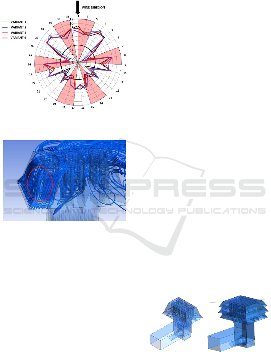
Figure 21: Distribution of mass flow rates through filters
with a wind of 20 m/s, flowing at an angle of 0° (filter
numbers correspond to Figure 13).
Figure 22: An additional vortex under the shield when the
wind hits "into the corner" (the angle of 135).
the weather shield, as in the case of windless weather,
provides the best inlet under the weather shield,
without additional vortex formation.
7 RECOMMENDATIONS FOR
THE DESIGN CHANGE
As a result of the study, recommendations are made
to change the baseline design of the IFU, which will
reduce hydraulic losses:
At the inlet to the space under the weather shield,
it is necessary to install baffles, which will
improve the performance of filters and PIC
(especially if there is wind).
For a more uniform entry of the working fluid and
reduction of inlet losses, the weather shield must
have an extension at the inlet, but its design can
be simplified.
To reduce clutter on the inlet section, the DIS
collector must be removed from section 0.
Changes in the design of the diffuser and sound
absorbing unit do not have a noticeable effect on
the hydraulic perfection of the shaft.
The presence of the rack in the turning channel
does not affect the level of losses, and it can be
removed from the design.
The layout of the filters must be revised to reduce
the number of abnormally operating filters. To
reduce losses at side wind, it is necessary to
increase the lateral projection of the filter box. In
the ideal case, the filter box must have a square
shape.
To reduce the backflow from the filter unit inside
it, it is necessary to install impermeable baffles.
8 INVESTIGATION OF LOSSES
IN MODERNIZED IFU
VARIANTS
Based on the recommendations given in the previous
section, 2 variants of IFU are developed.
Variant 5 - In general, it is identical to Variant 3,
but differs in the modified dimensions of the diffuser,
filter box and weather shield, as well as in
simplification of their shape (Figure 23).
Variant 6 - A variant which is characterized by a
rectangular-shaped filter box (Figure 24, in which (8
(in width)*6 (in length)*5 (in height) filters are
located), by the absence of sound absorbing panels and
by a weather shield with additional windows in the side
walls.
For both modernized variants, computational
models are created, similar to those described above.
The calculations show that Variant 5 has the hydraulic
characteristics close to the Variant 3. The magnitude of
the pressure loss increased by 40 Pa (5%).
Variant 5
Variant 6
Figure 23: Modernized IFU variants.
Reducing the Hydraulic Resistance in the Inlet Device of the Gas Turbine Unit
97
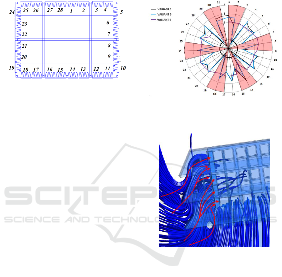
Figure 24: Adopted filter numbering in Variant 6 of IFU.
Variant 6 ensures the achievement of minimal
losses among all the considered variants of IFU. In
the absence of wind, the expected total hydraulic
resistance in the upgraded IFU is: initial - 260 Pa
(taking into account the resistance of clean filters of
75 Pa), final - 635 Pa (taking into account the
resistance of dirty filters of 450 Pa). This is 107 Pa
(15%) less than the baseline variant of the design (No.
1). The reason for the improvement is the absence of
sound absorbing panels, a lower level of losses at the
inlet and a greater uniformity of flow at the inlet to
the filter elements.
The average velocity at the inlet to the filter box
of the Variant 6 in calm weather is 1.78 m/s (for
comparison, in the baseline design (No. 1) is 3.01
m/s), at the inlet to the weather shield is 1.52 m/s (for
Variant 1 is 2.09 m/s). Note. The velocity of flowing
on the filter element recommended by the filter
manufacturer is less than 2.5 m/s.
In calm weather, the distribution of the flow rates
of the working fluid through the vertical rows of
filters of IFU No. 6 is close to uniform
(4.250.25 kg/s). In contrast to the previously
considered variants, in IFU No. 6 under no-wind
conditions there are no sections with a significantly
different level of mass flow rates of the working fluid,
or through which the working fluid flows out (Figure
25).
Variant 6 in windless weather provides a
significantly more uniform "loading" of filters, which
reduces the velocity level of air flowing on them. It
should also be noted a smaller difference in the
distribution of velocities (Figure 26) along the height
of the filter box which suggests that Variant 6
provides large flow rates through the upper filters
and, consequently, reducing flow rates through the
lower ones. These facts indicate more favourable
conditions for the operation of filter elements in
Variant 6.
Figure 25: The distribution of the flow rates of the working
fluid between the filters (numbers for variants1-5 - Figure
5, variant 6 - Figure 23 (pink areas correspond to the filters
in the "pockets" for variants 1-5).
Figure 26: The flow structure through the entrance windows
of the weather shield of the IFU No. 6 in calm weather.
In the presence of wind at 20 m/s, blowing strictly
into the face of the shaft, Variant 6 exceeds the
baseline variant (number 1) in hydraulic losses by
150 Pa. With the direction of the wind "from an
angle" (45° and 135°), the modernized variant shows
a higher level of losses by 150 Pa. The reason for the
increased losses in the characteristics of the air flow
in the space between the weather shield and the filter
box (Figure 27).
To reduce the intensity of vorticity and streamline
the flow structure under the weather shield, its shape
must be optimized, and internal baffles must be
installed similar to the baffles near the lower edge of
the weather shield. To select the shape and position
of these baffles, considering the effect on the
SIMULTECH 2019 - 9th International Conference on Simulation and Modeling Methodologies, Technologies and Applications
98

complexity of the maintenance of IFU, additional
research is necessary.
Figure 27: Dependence of the total loss of total pressure in
IFU of the main variants of the inlet shaft at a wind of
20 m/s with its different direction.
9 CONCLUSIONS
In the current research, a numerical simulation is
carried out of the air flowing in various variants of the
modernized inlet unit of the GPA-Ts-16 gas-pumping
unit with a two-stage cassette filter.
The values of total pressure losses in all elements
of IFU are calculated and the structure of the flow
inside is studied in detail for the absence or presence
of wind at a velocity from 0 to 35 m/s blowing from
5 main directions (0, 45, 90, 135, 180). Studies
are also carried out on the effect of the weather shield
shape, the presence of baffles under it, and the rack in
the shaft on the hydraulic losses.
As a result, the main sources of energy losses are
identified and recommendations for the design of
inlet shafts of this type are provided.
Based on the experience gained, an IFU
configuration is found that provides a reduction in
hydraulic losses relative to the baseline variant by
15%. Changing the IFU design will save 2.67 kg or
3.42 m3 per hour for each engine.
At the same time, the obtained design has reserves
for improvement due to streamlining the flow under
the weather shield using baffles.
The work carried out should be continued in the
direction of analyzing the work of the UFI de-icing
system and ensuring its effective operation in the
whole range of operating parameters.
Moreover, it is planned to validate simulation
results by experimental data after the inlet device will
be manufactured and tested.
ACKNOWLEDGEMENTS
This work was supported by the Russian Federation
President's grant (project code МК-3168.2019.8).
REFERENCES
Air inlet Filtration for GAS turbines, 2019. Access mode:
http://www.folter.ru/en/catalog/vozdushnye-filtry-
folter-dlya-gazovyh-turbin/.
Departmenr of Aircraft Engine Theory, 2019. Access mode:
http://tdla.ssau.ru.
Druzhba pipeline – Wikipedia, 2019. Access mode:
https://en.wikipedia.org/wiki/Druzhba_pipeline.
Gazprom, 2019. Access mode: http://www.gazprom.ru/.
INNOVAES | Innovación en Asuntos Estratégicos, 2019.
Access mode: innovaes.com.
JSC "Kuznetsov", 2019. Access mode:
http://www.kuznetsov-motors.ru/en.
RTEH GTD NK-16ST Vse o transporte gaza, 2019. Access
mode: http://www.turbinist.ru/6830-rte-gtd-nk-
16st.html.
Samara University, 2019. Access mode:
https://ssau.ru/english.
Supercomputer Center - Samara University, 2019. Access
mode: https://ssau.ru/it/supercomputer.
VolgaEnergoGaz, 2019. Access mode: http://www.v-eg.ru/.
Zabelin, N.A., Lykov, A.V., Rassokhin, V.A., 2013.
Calculation of available heat power of smoke fumes of
gasocompressor units of russia’s united gas
transmission system. Nauchno-tekhnicheskie
vedomosti Cankt-Peterburgskogo gosudarstvennogo
politekhnicheskogo universiteta. 4-1(183): 136-144.
Reducing the Hydraulic Resistance in the Inlet Device of the Gas Turbine Unit
99
