
Multi-level "Learnable" Model of the Workflow in the Centrifugal
Compressor Stage
Evgeny Marchukov
1
, Igor Egorov
1
, Oleg Baturin
2
, Grigorii Popov
2 a
and Andrei Volkov
2
1
Lyulka Design Bureau, Moscow, Russia
2
Samara National Research University, Samara, Russia
Keywords: Centrifugal Compressor, Mathematical Optimization Methods, Multidisciplinary Models, Multi-level
Mathematical Models.
Abstract: The paper presents the main ideas of the virtual test bench concept for rapid obtaining of the reliable
characteristics of compressors based on a multi-level mathematical model with a two-step identification using
data obtained from mathematical models with a high order of accuracy. One of the possible identification
algorithms and the results of its successful testing are given on the example of a centrifugal compressor stage
developed and tested at NASA. The authors created a pilot version of a digital analogue of a centrifugal
compressor. Its main feature is that it is created based on a multi-level mathematical model with a two-step
identification by the data obtained from mathematical models with a high order of accuracy.
NOMENCLATURE
G - mass flow rate of the working fluid,
kg/s
Z - Number of blades, pcs
K
- scale factor;
l - 2nd stage transformation ratio;
n - rotational speed, rpm;
- displacement of the characteristics in
the identification;
* - pressure ratio;
- efficiency
Y+ - non-dimensional wall distance
GTE - gas turbine engine;
CS - coordinate system;
FV - finite volume;
RW - rotor wheel
RD - radial diffuser
AD - axial diffuser
2D - referring to the simplified model;
3D - related to the model of high order
accuracy.
a
https://orcid.org/0000-0003-4491-1845
1 INTRODUCTION
The compressor is an important component of a gas
turbine engine that significantly affects the efficiency
of the engine cycle, fuel efficiency, reliability and
stability of work (Kulagin, 2002; Boyce, 2012). To
create a design that will be able to successfully
compete with competitors today, it is not enough to
obtain blades’ shape that provides the best flow
structure (which is in turn a difficult scientific and
engineering problem). Modern compressor, in
addition to providing the required pressure ratio with
maximum efficiency, must:
- withstand static and dynamic loads during the life
cycle;
- be cheap in production and operation;
- have a low noise level;
- be matched in the operation as the engine part;
- show the required characteristics from the first
delivery.
To successfully solve the problem of design and
calculation development of the compressor at the
modern level, it is necessary to involve a complex
multi-physical model (considering gas dynamics,
static and dynamic strength, manufacturing
technology, cost, acoustic processes, etc.) of high
100
Marchukov, E., Egorov, I., Baturin, O., Popov, G. and Volkov, A.
Multi-level "Learnable" Model of the Workflow in the Centrifugal Compressor Stage.
DOI: 10.5220/0007836801000110
In Proceedings of the 9th International Conference on Simulation and Modeling Methodologies, Technologies and Applications (SIMULTECH 2019), pages 100-110
ISBN: 978-989-758-381-0
Copyright
c
2019 by SCITEPRESS – Science and Technology Publications, Lda. All rights reserved

accuracy (3/4D based on equations with minimum
assumptions).
Summarizing the above, the task of designing or
modernizing a compressor today is the search for the
optimum of a multi-extremes, multi-criteria, multi-
disciplinary function of a huge number of variables,
the type and shape of which are not known, under the
conditions of many restrictions. This task is not
linear. It does not have a unique solution, and often
the same design solutions made in different
conditions lead to opposite results. For this reason,
the creation of a modern compressor is one of the
most difficult scientific and technical problems.
Finding the best combination of parameters
describing the compressor by simply enumerating the
options is the fortuity, not to mention that the human
brain is not able to systematically comprehend and
find the best combination of tens and hundreds of
variables regarding constraints. Therefore, such a
problem can be solved only with the use of
mathematical optimization methods (Vinogradov et
al., 2018; Popov et al., 2016; Komarov et al., 2015;
Siller et al., 2014).
The need to match the processes of the designed
compressor with the engine process requires to
determine in the calculation not just the values of the
main parameters at the operating point, but to find its
characteristic in a wide range of operating factors,
conducting several dozen calculations for one
combination of variable parameters. Since accurate
multidisciplinary models require several hours to get
a solution at one point, the time to determine the
characteristics for one compressor variant will be
calculated in days.
The application of complex multi-physical
mathematical models described by hundreds of
independent variables requires many iterations with
the computational model. Considering the above, the
search for the optimal solution of the task will require
an unacceptably long time, even with the use of
modern supercomputers. And the very problem of
finding the extremum of a function with hundreds of
variable parameters is a non-trivial task. If the
compressor consists of several stages or it is
necessary to design adjacent components (for
example, a turbine), or it is required to carry out
multi-criteria optimization, the described problem
becomes even more complicated.
Thus, the key problem of designing modern
compressors with outstanding characteristics is the
creation of a coherent complex of multi-level
mathematical models, which in a reasonable time can
simulate the operation of a compressor and its
elements at the earliest possible stages, prior to the
production of a prototype, identifying potential
defects and design variants that can not meet the
requirements of the technical specifications for some
reasons. This complex performs the same functions
as the test bench, so it can rightfully be called a
“virtual compressor test bench”.
2 ALGORITHM OF THE
VIRTUAL COMPRESSOR TEST
BENCH
To obtain data as close as possible to real ones in the
calculation, it is necessary to apply precise 3/4D
mathematical models describing the processes with
minimal assumptions. Their main disadvantage is a
great time for getting the result. At the same time,
there are many simplified physical models (1/2D
models, models with significant assumptions (for
example, for gas dynamics — the Euler equations),
etc.) that are not so accurate, but require a small
calculation time (seconds and minutes).
According to the authors of the paper, the key
technology that allows you to quickly and accurately
get the desired compressor variant with outstanding
performance (and will become the basis of a virtual
compressor bench) that meets the set technical
requirements is a coupled combination of the simplest
“fast and cheap” and complex “slow and expensive”
models. The main feature of the proposed version of
the virtual test bench is that it is built based on a multi-
level mathematical model with a two-stage
identification according to data obtained from
mathematical models with a high order of accuracy
(Fig. 1).
The core of the proposed methodology is a low
order accuracy model (for example, 1/2D). In it, the
characteristics of the compressor are calculated based
on known geometric data of the compressor (in the
form of a 3D model (often parametric)), a set of
drawings of elements or an array of data containing
information about the main geometric parameters of
the elements of the flow path) and simulated
conditions (from the experiment procedure). From the
obtained data, a test results report is generated, a copy
of which is archived.
The main disadvantage of the low-level model is
that the resulting characteristics have a large error due
to the strong simplification. Such models simplify the
geometry of the model (the radii of curvature, the
influence of the spatial alignment of elements, fillets,
etc. are not considered), and they also do not properly
simulate the energy losses.
Multi-level "Learnable" Model of the Workflow in the Centrifugal Compressor Stage
101
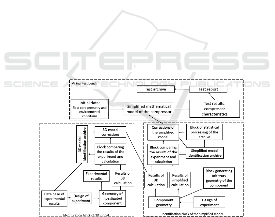
To eliminate this drawback in the proposed
version of the virtual stand, it is suggested to use the
identification block of simplified computational
models. The principle of its operation is to compare
the results of the calculation of the same component
using simplified methods and 3D (CFD) methods.
The latter, as noted, have minimal assumptions,
describe the geometry of the flow part without
simplifications and show the best accuracy among the
calculation methods known today. The calculation
results obtained in two ways are compared with each
other. As a result, corrections are found for a simple
model, and further research of the compressor is
carried out using characteristics calculated by the
identified simplified model.
As various projects are completed, the geometry
of the compressors and the results of their 3D and
simplified calculations will be accumulated in the
archive (database). As a result, an extensive
identification database will be accumulated in a much
wider range of geometric and operating parameters
than the specific problem being solved. Statistical
processing of archive data (creating regression
models) can find universal corrections for simplified
compressor models that can be used without
conducting many initial 3D calculations of a specific
task (one control calculation can be performed, which
results will be recorded in the archive). Statistical
processing of the archive must be conducted
periodically at regular intervals, constantly updating
the correction factors (teaching a simplified model).
Moreover, the identification block can exist, work
and “learn” independently from the virtual bench. To
do this, a block must be implemented that will
randomly generate the compressor geometry (with
changes in the basic parameters in a wide range,
screening options that are not possible for various
reasons), carry out a simplified and 3D calculations
of processes in them, record the results in the archive
and periodically process it. Such an approach will
allow obtaining continuously trained simplified
models of compressor workflows that are able to
calculate their reliable characteristics considering
many features of the component geometry. Such a
“training system” and the results of its operation is an
independent product that may be of interest to
compressor enterprises.
An important problem in identifying simplified
models is the accuracy of 3D simulation, according to
which the identification is carried out. To solve it, the
proposed variant of the virtual test bench includes a
block of identification of a 3D model based on the
results of experiments, which must find corrections
(settings) for 3D models that increase the accuracy of
calculations. As can be seen from Fig. 1, this block is
created on the principle of identifying a simplified
model. It is also possible to build an automatically
Figure 1: The principal flow diagram of the virtual test bench proposed by the authors for the investigation of the workflow
of compressors.
SIMULTECH 2019 - 9th International Conference on Simulation and Modeling Methodologies, Technologies and Applications
102
functioning algorithm for identifying 3D models with
periodically operating statistical processing of the
archive (training models). However, its
implementation is hampered by a small number of
available experimental results and a rare update of
their database.
3 OBJECT FOR CREATING A
PILOT VARIANT OF A
VIRTUAL TEST
The construction and development of a pilot variant
of the “virtual test bench” for testing compressors is
carried out using the example of a single-stage
centrifugal compressor. For this, a compressor
designed by NASA is chosen, and which
characteristics were comprehensively studied during
the experiment (Medic et al., 2014).
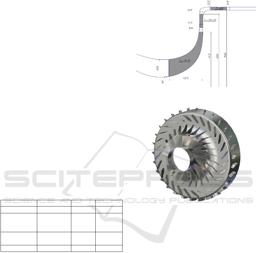
The main parameters of the compressor at the
design point are shown in Table 1. The main
geometric parameters of the compressor meridional
section are shown in Fig. 2. Its three-dimensional
model is shown in Fig. 3. The experimental
characteristics of the compressor obtained by NASA
(Medic et al., 2014) are shown in Fig. 7.
Table 1: The main parameters of the studied centrifugal
compressor.
Parameter
Designation
Units
Value
Rotor speed
n
rpm
22000
Air mass
flow rate at
the inlet
G
kg/s
5.1
Pressure
ratio
-
4.5
Efficiency
-
0.8
4 CREATION AND
VERIFICATION OF 3D
NUMERICAL MODEL OF
COMPRESSOR WORKFLOW
Based on a detailed description of the compressor
geometry and the results of its experimental studies
(Medic et al., 2014), a 3D numerical model (high-
level model) of its gas-dynamic processes is created
in the Numeca FineTurbo (NUMECA, 2008).
The computational domain consists of three
subdomains (rotor wheel, blade and axial diffusers)
(Fadilah et al., 2018; Hunziker et al., 2001;
Figure 2: Meridional shape of a centrifugal compressor.
Figure 3: Three-dimensional model of the investigated
centrifugal compressor.
Erdmenger et al., 2014; Casey et al., 2013; Rusch et
al., 2013). Each of the subregions consisted of one
blade passage with periodic boundary conditions on
the lateral surface. The RW domain is calculated in
the moving coordinate system, rotating with the rotor
speed, the other domains are considered in the fixed
CS. Flow parameters between subdomains are
transmitted using the Full Non Matching Mixing
Plane interface, which averages in the circumferential
direction the flow parameters at the outlet of one
domain and transfers them to the inlet to the
downstream domain as inlet boundary conditions.
As the boundary conditions at the inlet of the
centrifugal compressor, the values of the total
pressure (101325 Pa) and the total temperature (288
K) are set (Rusch et al., 2013; Tomita et al., 2012;
Verstraete et al., 2010). At the outlet of the centrifugal
compressor, the static pressure is set on the hub
section. The value of static pressure is selected from
Multi-level "Learnable" Model of the Workflow in the Centrifugal Compressor Stage
103
the condition of providing the necessary point on the
characteristics of the compressor.
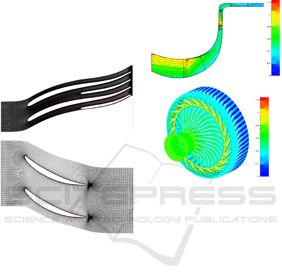
The finite volumes mesh is created in such a way
that the value of the parameter
on the walls of the
computational domain is equal to 1 (Verstraete et al.,
2010; Geller et al., 2017; Guo et al., 2015; Liu et al.,
2010; Li et al., 2016; Hehn et al., 2018). The total
number of elements is 3.2 million. The appearance of
the FV mesh is shown in Fig. 4.
Rotor wheel
Axial diffuser
Figure 4: Finite volume mesh of a 3D computational model
of the centrifugal compressor.
The flow structure (Mach numbers) in the
compressor at the design point is shown in Fig. 5.
Comparison of the pressure and efficiency
characteristics obtained as a result of 3D calculations
(Fig. 6) at the rotor speed of with the
corresponding experimental data indicates their good
qualitative and quantitative coincidence. The
appearance of the characteristics of the investigated
compressor, obtained using the created computational
3D model, which will later be used to identify the
simplified one is shown in Fig. 7.
Averaged in the meridional section
In the middle section
Figure 5: Calculated contours of Mach numbers in the
relative motion at the design point, obtained for the
compressor using computational 3D model.
5 CHARACTERISTICS OF THE
CENTRIFUGAL COMPRESSOR
CREATED USING A
LOW-LEVEL DESIGN MODEL
For the centrifugal compressor taken as an example,
a simplified 2D model of its workflow in it is created
for the same initial data. With its help, the
characteristics of the compressor are obtained. They
are shown in Fig. 7 in comparison with the
characteristics obtained by the 3D model, verified by
experimental data. As can be seen, the results of 2D
modeling have a noticeable qualitative and
quantitative discrepancy with the reference data.
SIMULTECH 2019 - 9th International Conference on Simulation and Modeling Methodologies, Technologies and Applications
104
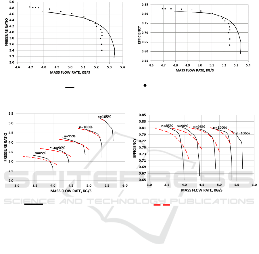
Pressure characteristics
Efficiency characteristics
- Results of 3D calculation; - Experimental data
Figure 6: Comparison of the experimental and calculated (using a 3D model) characteristics of the centrifugal compressor at
a rotor speed of 100%.
Pressure characteristics
Efficiency characteristics
- Results of 3D calculation
- Results of 2D calculation
Figure 7: Characteristics of the investigated centrifugal compressor, obtained using 3D and a simplified 2D computational
models of the workflow.
6 IMPLEMENTED ALGORITHM
FOR THE IDENTIFICATION OF
SIMPLE MATHEMATICAL
MODELS BY HIGH-LEVEL
MODELS
The main purpose of identifying a mathematical
model by a high-level design model is to find such
corrections, the use of which will bring the results of
the calculation of a low-level mathematical model as
close as possible to the reference ones (obtained in the
experiment or using an identified high-level model).
In this case, the identifying corrections must be a
function depending on many operational and
geometric parameters. To obtain reliable universal
correction factors that minimize the error in modeling
an arbitrary problem, it is necessary to analyze a large
database of matching results.
In relation to the current problem, identification
(approximation of the design characteristics of the
compressor to the reference ones) can be carried out
in two principal ways:
‒ by the correction of empirical coefficients of the
low-level mathematical model (firstly, the
coefficients of the energy loss model);
‒ by the mechanical transformation of the
characteristics obtained using the low-level model, so
that it comes close to the reference.
The first approach looks more reasonable, but the
second one can be implemented with lower costs. The
latter will be further applied. The following describes
the algorithm developed by the authors to identify a
simplified mathematical model of a centrifugal
compressor, described in Section 3, based on the
Multi-level "Learnable" Model of the Workflow in the Centrifugal Compressor Stage
105
results of a calculation using a 3D model used in
constructing a pilot variant of a virtual test bench.
Fig. 7 shows a comparison of compressor
characteristics obtained using 2D mathematical
model of the centrifugal compressor and the reference
3D model. To combine the corrected and reference
characteristics, the first of them must be shifted and
scaled along both coordinate axes. This manipulation
must be done with both (
and efficiency)
characteristics of the compressor.
The connection between the points of the original
2D and the adjusted characteristics at a constant rotor
speed can be written as follows:
where
,
,
–offset of characteristic lines;
,
,
–scaling factors of the characteristic lines.
These coefficients for the fixed rotor speed are
calculated as follows:
These coefficients are calculated for all pressure
lines (lines of constant rotational speed). As a result,
an array of data of the form
,
,
,
,
,
=f(n) is created. The data available in it is
interpolated by some functions:
,
,
,
,
,
=f(n).
Identification of 2D characteristics of the
centrifugal compressor, carried out for an example
compressor, showed that the displacement of the
characteristic lines are most accurately interpolated
by the function
, and the scaling
coefficients of the characteristic lines are a third-
degree polynomial
.
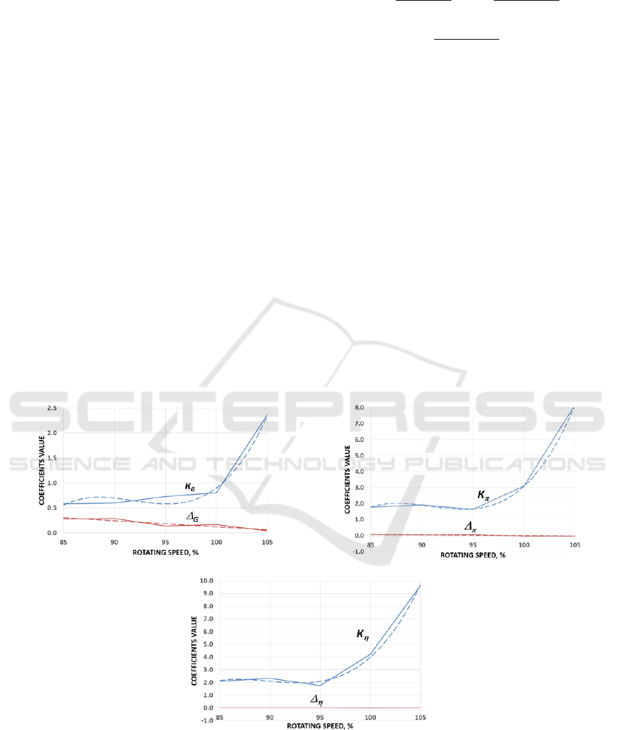
Examples of the obtained coefficients and their
interpolation for the centrifugal compressor of a
virtual prototype are shown in Fig. 8.
For the mass flow rate through the compressor
For pressure ration
For efficiency
Figure 8: The results of calculating the transformation coefficients in identifying 2D characteristics of a virtual prototype
(solid line) and their interpolation (dashed line).
SIMULTECH 2019 - 9th International Conference on Simulation and Modeling Methodologies, Technologies and Applications
106
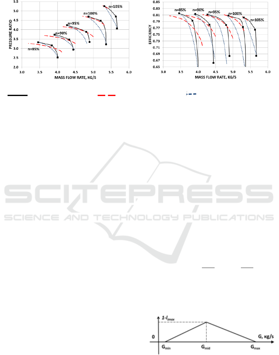
Pressure characteristics
Efficiency characteristics
- Results of 3D calculation; - Results of 2D calculation Corrected 2D model (stage 1)
Figure 9: Transformation of compressor characteristics at the first stage of identification.
As can be seen from Fig. 8, the interpolation
equations are obtained only by 5 points, and show a
relatively high error. It is obvious that the
accumulation of identification statistics should
significantly reduce it.
Using the found interpolation equations, the
transformation coefficients are calculated and the
original 2D characteristic is recalculated. The results
of the described transformation are shown in Fig. 9.
As can be seen from the presented results, the
corrected characteristics show good qualitative
agreement, but at the same time, the quality is not
satisfactory.
To solve this problem, the algorithm described
above is upgraded. The essence of the modernization
lies in the addition of the “qualitative correction”
algorithm (the second stage of transformation), when
a certain middle point of the calculated curve is
combined with the same point of the reference curve.
This algorithm works as follows. A “characteristic
point” is selected on the reference curve (this point
receives the index “mid”) that is the point of
discontinuity of the curve (indicated in Fig. 9). To
determine it, the tangents are calculated at the points
describing the characteristic lines and their change
when going from one point to the next in the direction
of growth of the working fluid mass flow rate. In the
place where the angle of inclination of the tangent is
changed to the largest value is the point of maximum
discontinuity (mid). Then, the angular coordinate of
the found point in the polar coordinate system with
the center at the origin is calculated. The point with a
close value of the angular coordinate in the same CS
is on the transformed curve.
Further transformation of the characteristics can
be carried out in the following way. At the second
stage of the correction (“quality correction”) occurs
only along the vertical axes:
where
,
are correction factors.
It is assumed that the value of the correction
factors
with the change in flow rate varied in
accordance with Fig. 10. The change in the magnitude
of the correction factor between the maximum and
extreme values is assumed to be linear.
The value of the maximum correction factors is as
follows:
The maximum correction factors are found for all
calculated lines corresponding to a constant rotation
frequency and then interpolated by the function
.
Figure 10: The adopted pattern of change of the correction
factors
.
Multi-level "Learnable" Model of the Workflow in the Centrifugal Compressor Stage
107
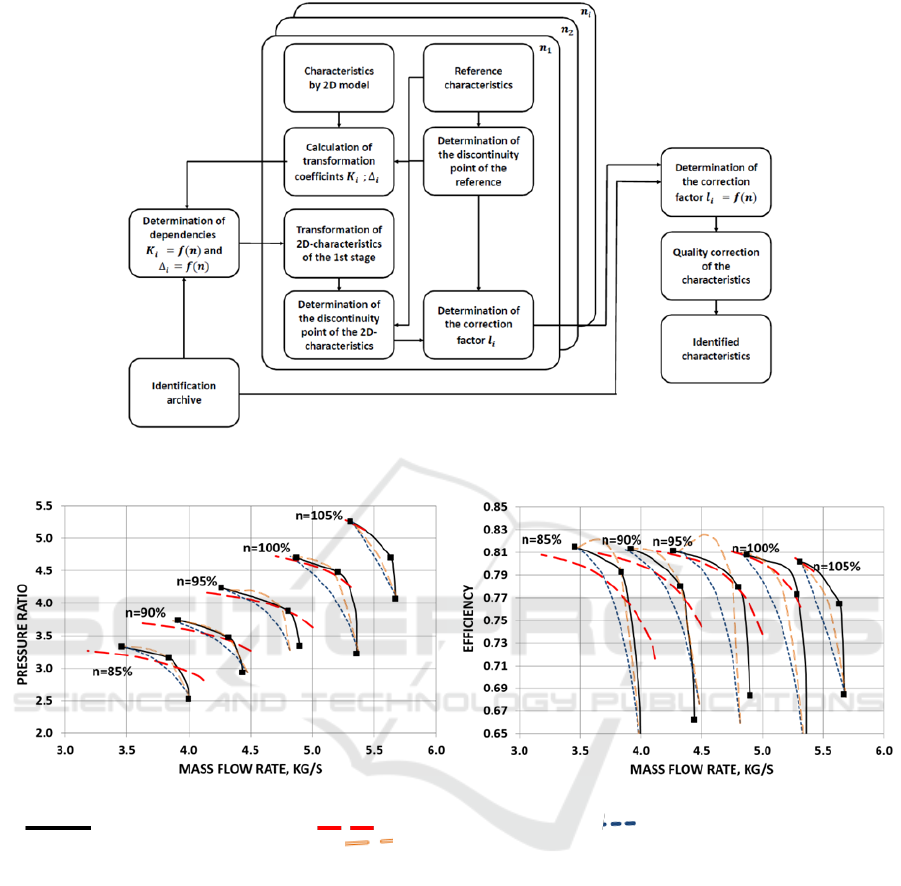
Figure 11: The flow diagram of the identification of mathematical models using the transformation characteristics.
Pressure characteristics
Efficiency characteristics
- Results of 3D calculation; - Results of 2D calculation Corrected 2D model after the
1st transformation stage; - 2D model after the 1st transformation stage
Figure 12: The result of a two-step transformation of 2D characteristics during identification.
A flow diagram of the identification process used in
the centrifugal compressor is shown in Fig. 11. The
results of the transformation of the compressor
characteristics after stage 2 are shown in Fig. 12. As
can be seen, the transformation allowed for a good
agreement between the corrected and reference
characteristics, especially for n=90 and 100%. The
qualitative distortion of the characteristic lines at
other rotor speeds is caused by a small number of
calculation points, which introduced a significant
error in the determination of the “maximum inflection
point” (mid) on the 2D calculation curve.
7 CONCLUSIONS
In the course of the project, the authors developed the
concept of a virtual test bench based on
simplifiedmathematical models with two-step
identification by the results of calculations using
high-level models and experimental data in order to
obtain reliable characteristics of the compressor.
According to this concept, characteristics obtained
using 1/2D mathematical models of components are
used to accelerate the obtaining of the results. They
are based on relatively simple correlations and require
a short calculation time, but have significant error. To
SIMULTECH 2019 - 9th International Conference on Simulation and Modeling Methodologies, Technologies and Applications
108

eliminate this drawback, 1/2D calculation models are
identified by the results of 3D calculations. The latter
have minimal assumptions and show the best
accuracy among the calculation methods known
today. Based on the comparison, corrective
corrections are found for the 1/2D model. 3D models
in turn are identified by the test results. When creating
identification blocks, “learning” algorithms for 1/2D
and 3D models are proposed.
An algorithm for identifying simplified models
using high-level models is developed and
successfully tested.
The developed algorithms and pilot samples of the
virtual compressor test bench are the first steps of a
fully-featured “bench”, which will be able to replace
most of the field tests. The virtual bench will allow to
model a larger range of impacts on the object under
study, including those that cannot be reproduced on
existing benches or require huge material and energy
costs. Modern development of automated tools and
tools for the design of gas turbine engines,
processing, management and accumulation of
information allows us to believe in the successful
solution of this problem and the achievement of a
qualitative leap forward in the characteristics and
capabilities of virtual test benches.
ACKNOWLEDGEMENTS
This work was supported by the Russian Federation
President's grant (project code МК-3168.2019.8).
REFERENCES
Boyce, M., 2012. Gas Turbine Engineering Handbook, Gas
Turbine Engineering Handbook, Butterworth-
Heinemann, Elsevier, MA. 4th ed.
Casey, M. and Robinson, C. 2013. A Method to Estimate
the Performance Map of a Centrifugal Compressor
Stage. Journal of Turbomachinery, 135 (2): 021034
Dubitsky, O., 2017. Optimization of Cycle Parameters, Fuel
Consumption, and Weight of a Turboshaft Engine
Using 1D Design Tools. Concepts NREC SpinOffs |
Turbomachinery Blog.
Erdmenger, R.R. and Michelassi, V. 2014. Impact of Main
and Splitter Blade Leading Edge Contour on the
Performance of High Pressure Ratio Centrifugal
Compressors. Proceedings of the ASME Turbo Expo,
GT2014-27062
Fadilah, P.A. and Erawan, D.F. 2018. Small centrifugal
compressor performance trend prediction based on
computational fluid dynamic. Paper presented at
the Journal of Physics: Conference Series, 1130(1)
Geller, M., Schemmann, C. and Kluck, N., 2017.
"Optimization of the Operation Characteristic of a
Highly Stressed Centrifugal Compressor Impeller
Using Automated Optimization and Meta-Modelling
Methods. Proceedings of the ASME Turbo Expo,
GT2017-63262
Guo, Z., Song, L., Zhou, Z., Li, J. fnd Feng, Z. 2015. Multi-
Objective Aerodynamic Optimization Design and Data
Mining of a High Pressure Ratio Centrifugal Impeller.
Journal of Engineering for Gas Turbines and Power,
137 (9), № 092602
Hehn, A., Mosdzien, M., Grates, D. and Jeschke, P. 2018.
Aerodynamic optimization of a transonic centrifugal
compressor by using arbitrary blade surfaces. Journal
of Turbomachinery, 140 (5): 051011
Hunziker, R., Dickmann, H.-P. and Emmrich, R. 2001.
Numerical and experimental investigation of a
centrifugal compressor with an inducer casing bleed
system. Journal of Power and Energy, 215 (6): 783-791
Komarov, O.V., Sedunin, V.A., Blinov, V.L., Serkov, S.A.
and Brodov, Yu.M., 2015. The effect of optimization
problem definition in 2D compressor airfoil.
Proceedings of the ASME Turbo Expo, GT2015-44043.
Kulagin, V.V., 2002. Teoria, raschet i proektirovanie
aviacionnyh dvigateley i energeticheskih ustanovok.
Uchebnik. Osnovy teorii GTD. Rabochiy process i
termodinamicheskiy analiz (The theory, calculation
and design of aircraft engines and power plants: a
Textbook. Fundamentals of the theory of the CCD.
Workflow and thermodynamic analysis),
Mashinostroenie, Moskow.
Li, X., Zhao, Y., Liu, Z. and Chen, H. 2016. The
Optimization of a Centrifugal Impeller Based on a New
Multi-Objective Evolutionary Strategy. Proceedings of
the ASME Turbo Expo, GT2016-56592
Liu, X.M. and Zhang, W.B. 2010. Two Schemes of Multi-
Objective Aerodynamic Optimization for Centrifugal
Impeller Using Response Surface Model and Genetic
Algorithm. Proceedings of the ASME Turbo Expo,
GT2010-23775
Medic,G., Sharma, O.P., Jongwook, L., Hardin, L.W.,
McCormick, D.C., Cousins, W.T., Lurie, E.A., Shabbir,
A., Holley, B.M. and Van Slooten P.R., 2014. High
Efficiency Centrifugal Compressor for Rotorcraft
Applications. NASA/CR-2014-218114.
NUMECA, 2008. User Manual AutoGrid5 Release 8.4,
NUMECA.inc., Belgium.
Popov, G., Goriachkin, E., Kolmakova, D. and Novikova,
Y. "Multicriteria optimization of axial low pressure
compressor of gas turbine power plant", Proceedings of
the ASME Turbo Expo, 2016, GT2016-57856.
Rusch, D. and Casey, M. 2013. The design space
boundaries for high flow capacity centrifugal
compressors. Journal of Turbomachinery, 135 (3):
031035
Siller, U., Kröger, G., Moser, T. and Hediger, S., 2014.
Towards a highly efficient small scale turboshaft
engine. Part II: Aero-mechanical turbine design and
optimization. Proceedings of the ASME Turbo Expo,
GT2014-26320.
Multi-level "Learnable" Model of the Workflow in the Centrifugal Compressor Stage
109

Tomita, I., Ibaraki, S., Furukawa, M. and Yamada, K. 2012.
The Effect of Tip Leakage Vortex for Operating Range
Enhancement of Centrifugal Compressor. Proceedings
of the ASME Turbo Expo, GT2012-68947
Verstraete, T., Alsalihi, Z. and Van den, R.A. 2010.
Multidisciplinary optimization of a radial compressor
for microgas turbine applications. Journal of
Turbomachinery, 132 (3): 031004
Vinogradov, K.A., Kretinin, G.V., Leshenko, I.A.,
Otriakhina, K.V., Fedechkin, K.S., Vinogradova, O.V.,
Bushmanov, V.V. and Khramin, R.V., 2018. Robust
multiphysics optimization for fan blade aerodynamic
efficiency, structural properties and flutter sensitivity.
Proceedings of the ASME Turbo Expo, GT2018-76816.
SIMULTECH 2019 - 9th International Conference on Simulation and Modeling Methodologies, Technologies and Applications
110
