
Vision of the TFM-driven Code Acquisition
Vladislavs Nazaruks
a
and Jānis Osis
b
Department of Applied Computer Science, Riga Technical University, Sētas iela 1, Riga, Latvia
Keywords: Topological Functioning Model, Code Generation, Code Acquisition, Model Transformation, System
Analysis, Knowledge Frame.
Abstract: Code acquisition from the system (domain) model completely depends on quality of the model. This paper
presents the general vision of the TFM-driven code acquisition. The TFM (Topological Functioning Model)
keeps knowledge about the system (domain) functioning, behavior and structure obtained from verbal
descriptions of the system (domain). The open question is how this knowledge covers source code constructs.
The result shows that, indeed, the final code contain this knowledge, but constructs for representation may
differ corresponding to the architectural decisions.
1 INTRODUCTION
Code acquisition (or generation) from models is not a
new topic. It remains topical since 2001, when the
Object Management Group published their guide on
Model Driven Architecture (Miller and Mukerji
2001). Model Driven Architecture (MDA) suggests
focusing on formal (computer-understandable)
models and their transformations with incremental
decrease of the level of abstraction and adding details
specific to applications, architectures and platforms.
The more formal a model is, the higher its
accuracy in representation of the domain under
analysis is. The suggested technique uses formal
models for knowledge representation, modelling and
analysis, namely a Topological Functioning Model
(TFM) and knowledge frames (Nazaruks 2017). The
TFM is a formal model which describes functioning
of the system (Osis 1969), where functional
characteristics of the system are related to each other
using cause-effect relations that form topology of the
system functioning. The TFM can be transformed to
design models in form of special UML (Unified
Modelling Language) profile called the Topological
UML (Osis and Donins 2017). The model obtained as
a result of such transformation needs to be manually
refined to be able to produce executable code.
The open question is what exactly the acquired
code presents, does it completely specify needed
a
https://orcid.org/0000-0003-4335-707X
b
https://orcid.org/0000-0003-3774-4233
functionality or can serve as a skeleton of obligatory
implementable functionality, behavior and structure.
The goal of this paper is to present a vision of how
to acquire the source code of the software given a
textual description of the business domain and
software requirements, by using the TFM-based
knowledge frames.
Section 2 presents the overview of related work,
Section 3 gives a brief explanation on the TFM,
Section 4 presents the general vision of code
acquisition from the TFM-based knowledge frames
and illustrates it by the small example of the fragment
of the functioning system in Section 5. Section 6
concludes the paper with main results and brief
discussion on them.
2 RELATED WORK
Since 2001, code generation has been a topical
subject. The source models for code acquisition can
be in different languages, e. g. UML, Object
Constraint Language (OCL), or Domain Specific
Modeling Languages (DSMLs). As we have
mentioned in Introduction, in our vision the source
model is the knowledge frame system based on the
TFM.
The approach that shares similar principles to our
vision is presented by the concept of Model
Nazaruks, V. and Osis, J.
Vision of the TFM-driven Code Acquisition.
DOI: 10.5220/0007843306170624
In Proceedings of the 14th International Conference on Evaluation of Novel Approaches to Software Engineering (ENASE 2019), pages 617-624
ISBN: 978-989-758-375-9
Copyright
c
2019 by SCITEPRESS – Science and Technology Publications, Lda. All rights reserved
617

Integrated Computing (MIC), where a domain model
that represents system and customer’s demands is
constructed using a domain meta-model as a DSML
(Wang et al. 2010). Then the model interpreter
generates the application program from the domain
model. In our vision we do not use DSMLs but stay
at the idea on using formalized version of the UML.
Other authors use the principle of similarity of
source and target languages. For instance, Egea and
Dania (Egea and Dania 2017) applied this principle in
their solution for transforming OCL expressions into
SQL Procedural languages. We can note that this
principle is also being used in our vision, since
knowledge frames and object-oriented programming
constructs and concepts overlap in a large degree. M
T and Sherly (M T and Sherly 2014) used refactoring
UML sequence diagrams in the XMI (XML Metadata
Interchange) format by using OCL constructs in order
to generate proper source code.
Many researchers put their efforts into research on
code generation from UML models, its executable
versions (Alf, fUML, etc.) or profiles like, for
instance, an approach presented by Hili et al. (Hili et
al. 2017). Ciccozi et al. (Ciccozzi et al. 2011)
demonstrated transformation from the design model
to executable code in Action Language for
Foundational UML (Alf). Their aim is to provide full
code generation that covers also extra-functional
characteristics of the application program. Our vision
also has the same aim, however, in this paper we skip
discussion of extra-functional requirements. Bhullar
et al. (Bhullar et al. 2016) gave a very interesting
survey on UML diagram-based code generation
methods. The authors limited the survey with
behavioral UML diagrams such as activity diagrams,
sequence diagrams, use case diagrams etc. As the
authors noted none of the considered methods is
appropriate to give 100% code generation. Additional
activities include some enhancement methods and re-
factorization methods to achieve code up to the
maximum possible extent. Another aspect of code
generation from UML models is a difference in
implementations of UML versions in modelling tools.
As Noyer et al. indicated (Noyer et al. 2014), code
generation may give unexpected results due to
implementation particularities of both UML and
target languages. Another interesting aspect is that
many authors pay their main attention to UML class,
sequence and activity diagrams.
Wang et al. (Wang et al. 2017) presented their
solution for rapid realization of executable domain
models. This solution combines agility with
principles of model driven development for small
functional parts of the system and uses as UML as
domain specific languages. Shiferaw and Jena
(Shiferaw and Jena 2018) illustrated model to code
and code to model generation possibilities. The main
aspect covered in this research is keeping model and
code consistent allowing repeated generation from
code and integration of code into a UML model.
Since transformations may be multiple and may
involve different models, the support of model
transformation chains is very important. Guana et al.
propose ChainTracker, a tool the main aim of which
is to assist in this task (Guana et al. 2014).
Concluding, adequacy of generated code and its
model still is a challenge that covers many aspects
starting from model adequacy to its domain (or
domains) and ending with variations in
implementations of languages in tools used for code
generation.
3 TOPOLOGICAL
FUNCTIONING MODEL
The TFM is a formal model which describes system
functioning. Its fundamentals are published by Janis
Osis in 1969 (Osis 1969). The TFM can be specified
as a topological space
(
𝑋, Θ
)
, where 𝑋 is a finite set
of functional features of the system under
consideration, and Θ is a topology on 𝑋.
A functional feature is “a characteristic of the
system (in its general sense) that is designed [for] and
necessary to achieve some system’s goal” (Osis and
Asnina 2011). It can be specified by a unique tuple
(1):
〈
𝐴, 𝑅, 𝑂, 𝑃𝑟𝐶𝑜𝑛𝑑, 𝑃𝑜𝑠𝑡𝐶𝑜𝑛𝑑, 𝑃𝑟, 𝐸𝑥
〉
(1)
where:
𝐴 is an action linked to a [domain] object,
𝑅 is a result of action 𝐴 (optional),
𝑂 is an object (objects) that gets the result of
the action or an object (objects) that is used in
this action,
𝑃𝑟𝐶𝑜𝑛𝑑 is a set of preconditions or atomic
business rules,
𝑃𝑜𝑠𝑡𝐶𝑜𝑛𝑑 is a set of postconditions or atomic
business rules,
𝑃𝑟 is a set of responsible entities (systems or
subsystems) that provide or suggest action 𝐴
with a set of certain objects,
𝐸𝑥 is a set of responsible entities (systems or
subsystems) that enact concrete action 𝐴 (Osis
and Asnina 2011; Nazaruka et al. 2016).
MDI4SE 2019 - Special Session on Model-Driven Innovations for Software Engineering
618
Topology set over functional features is a set of
cause-effect relations that in design models are
transformed into control, message and transition
flows (Osis and Donins 2017).
A TFM is valid when it satisfies topological and
functioning properties (Osis and Asnina 2011). The
topological properties are connectedness,
neighborhood, closure and continuous mapping. The
functioning properties are cause-effect relations,
cycle structure, inputs and outputs. The possibility of
validation of the TFM by using simulation of
execution models is discussed by Ovchinnikova and
Nazaruka (Ovchinnikova and Nazaruka 2016), where
decision making is based on previously presented
results (Asnina and Ovchinnikova 2015).
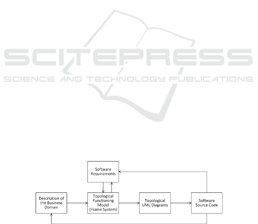
4 CODE ACQUISITION
The general vision of software source code
acquisition from the TFM-based knowledge system is
illustrated in Figure 1. We have the following inputs:
a textual description of the business domain for
which the software is being constructed,
software functional requirements, which
extend or change some parts of the description
of the business domain to give a picture of what
must be implemented in software.
From these inputs, we can obtain the TFM of the
system in form of knowledge frame system (Nazaruks
2017). Software requirements are verified in
compliance with knowledge from the business
domain description presented in the TFM-based
frame system. Then, by transforming the TFM, we
can get a set of Topological UML diagrams (Osis and
Donins 2017). In this paper, we consider only a
sequence diagram of the information system. When
we have a specific UML sequence diagram, we can
transform it (at the moment, manually) to source code
in some concrete imperative programming language
(for example, Java, C#).
Source code acquired by using transformation of
the UML sequence diagram is not complete source
code of the information system — it has a number of
limitations. For example, logic of data persistence
must be added to source code to be able to store and
load data. Also, in such source code, there are no
specific algorithms for data processing. Moreover,
the architecture of obtained source code is “flat” —
this means that there are no architectural patterns (for
example, client-server architecture, layered
architecture) associated with the source code.
However, such source code can be used at least in
the following ways:
as a prototype of the information system, which
lets the user go through different execution
scenarios (or alternatives, as in sequence
diagrams),
as a basis for implementing missing parts of the
information system.
as a skeleton of required functionality and
control flows in scenario execution.
At the present, in our vision we pay our main attention
to getting source code that could be used as a
prototype of behavior of the information system.
Feedback from generated source code goes to
textual descriptions of the domain itself and to
specification of the software requirements.
Knowledge from the updated specifications and
descriptions are updated in the knowledge base.
Transformation from the TFM functional feature
tuple (1) into a topological UML sequence diagram
elements is presented in (Osis and Donins 2017;
Nazaruka 2017):
The input for this transformation is a context
(e. g. a use case), the TFM, and mappings
between functional features and functional
requirements. The last ones are necessary to
verify that all required functional
characteristics and no one manual (or other
system’s) functionality are implemented.
Figure 1: General vision of the software source code acquisition from the Topological Functioning Model.
Vision of the TFM-driven Code Acquisition
619
Actors are added directly according to the
defined context. In the TFM actors are
presented as elements of the set Ex (executors).
The TFM and mappings allow establishing
objects with lifelines; messages they send each
other are based on cause-effect relations among
corresponding functional features.
In other words, domain object O is transformed to the
object with lifeline if it is not of a primitive type.
Action A is transformed to the message send to object
O, and direction as well as chronological sequence of
this message is determined by the corresponding
cause-effect relation (Osis and Donins 2017).
Establishing messages between objects as well as
their sequence is achieved by transforming a fragment
of TFM according to the chosen context. All vertices
with objects of the same type are merged keeping
cause-effect relations between them. A cause-effect
relation is transformed to the message flow between
objects of the corresponding types. The interaction
operators are added: alt for optional cause-effect
relations (logical operators OR and XOR), opt — for
OR, and par — for the set of necessary cause-effect
relations (logical operator AND). Interaction
operators alt and opt have a conditional expressions,
called guards, that are taken from set PreCond of the
tuple (1) of the corresponding functional feature (Osis
and Donins 2017).
Included contexts are represented applying
interaction use (ref) for the included sequence
diagram (Osis and Donins 2017).
The initial transformation procedure presented in
(Osis and Donins 2017) does not deal with user
interfaces or programmable interfaces in sequence
diagrams. In the presented vision, we suggest adding
an object that is responsible for communication with
the user interface. Therefore, each actor whose
functional features must be implemented in software
will have a corresponding object —
<Actor>Interface. The responsibility of
<Actor>Interface is to get messages from a user
interface and transfer them to the object responsible
for the corresponding action. Transformation from
the UML sequence diagram to code is standard (Osis
and Donins 2017) as described above.
In order to emulate user interfaces the method
that controls execution of scenarios must be
added, in case of the prototype it is method
main(). This method contains: Data structures
Map<Integer, String> for choices in scenarios,
where the first parameter contains an identifier
of the functional feature and the second one
contains its description, where verb of action A
is transformed to the gerund.
Control structure switch() for scenarios
depending on the choice made.
Method AskNextStep(Map<Integer, String>
steps) that asks a user to make a choice in
runtime and waits for their response.
Each step in a scenario is an invocation of the
corresponding method of the object responsible for its
execution.
Figure 2: The fragment of the TFM corresponding to the description of the business domain.
MDI4SE 2019 - Special Session on Model-Driven Innovations for Software Engineering
620
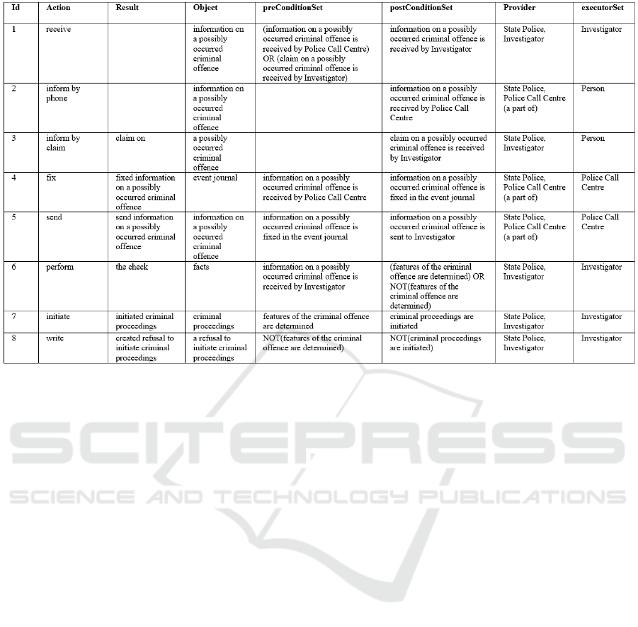
Figure 3: Functional features of the obtained TFM (frame class instances).
5 PRACTICAL
DEMONSTRATION
In this section, we demonstrate the process of code
acquisition using a small example. The fragment of
the business domain description is as follows:
“To initiate criminal proceedings, an investigator
must receive information on a possibly occurred
criminal offence. Usually, the investigator receives
this information when some person informs the police
call center about the criminal offence by phone or the
investigator personally by means of a claim. The
police call center fixes the received information in the
event journal and sends it to the investigator. When
the investigator receives the information on the
criminal offence, they perform a check of the facts,
and if they determine the features of the criminal
offence then they initiate criminal proceedings. If not,
they write a refusal to initiate criminal proceedings.”
For the reason of simplicity, we consider only the
fragment of the business domain description, not the
complete description. This simplification will affect
the model obtained: in this example, the model will
not have one of TFM obligatory parts — topological
cycle. In other words, here we consider only a
fragment of the TFM that represents a business
process (or the context for transformation to the
sequence diagram). However, this will not prevent us
from acquiring source code from such a model.
The fragment of the model obtained from the
description of the business domain is shown in
Figure 2. The functional features of this fragment are
shown in Figure 3.
Given the TFM and knowledge what functional
features are to be implemented in the information
system, we can obtain the UML sequence diagram of
behavior of the information system in the given
context.
Let us assume that the following functional
features will be implemented in the information
system: 1, 4, 5, 7, 8. This means that functional
features 2, 3, 6 will be executed manually by the
corresponding actors. Assuming this, the resulting
UML sequence diagram of the given context will be
as shown in Figure 4.
However, our aim is to produce source code that
can be used as a prototype of the application
functionality. Taking into account the limitations of
the “flat” architecture of source code that can be
obtained from the UML sequence diagram (see
Section 4), we modify the sequence diagram in a way
that the role of actors will perform the main class of
the application — therefore we avoid the necessity to
introduce multiple user interfaces (in our example —
for actors Police Call Centre and Investigator) at the
Vision of the TFM-driven Code Acquisition
621
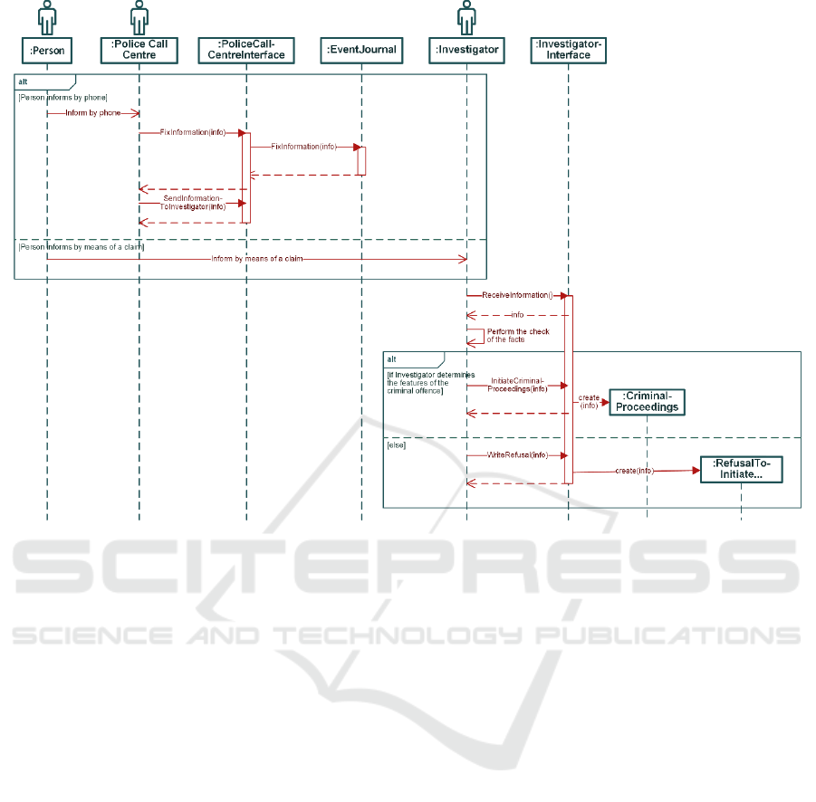
Figure 4: UML sequence diagram of the application.
very beginning. The modified sequence diagram —
the UML sequence diagram of the prototype of the
program — is shown in Figure 5.
Finally, from that modified sequence diagram we
obtain the source code for the prototype of the
application. The simplified source code in the Java
programming language is presented in Appendix.
In the source code of the prototype, we assume the
following facts: there is only one actor in the Police
Call Centre, and there is only one Investigator.
6 CONCLUSIONS
Code acquisition from domain models still is a
challenge. Domain models can be presented using
domain-specific modeling languages, languages
similar to the target ones, general-purpose languages
like UML, or specific ones like UML profiles.
Domain specific modeling languages allow modeling
very specific domains, developing specific
transformations and achieving almost completely
working code.
In case of general-purpose languages, the
situation is not so good. The quality of generated code
is lower. Reasons are different, but the primary one is
inadequate representation of the domain in the model.
Inadequacy can be expressed as incomplete
information, wrong constructs, undefined cause-
effect relations in the domain.
This paper presents a vision on how the formal
domain model, TFM-based frame system, can be used
to deal with some of these issues, i. e. incomplete
information and definition of cause-effect relations in
the domain. The code acquisition is based on a chain
of transformations and can be used as a running
prototype for analysis of scenarios in the application,
or as a skeleton of functionality and execution
scenarios that mandatory must be implemented
further in the application.
Future research directions are related to the
elaboration of the presented vision as a working tool
set.
MDI4SE 2019 - Special Session on Model-Driven Innovations for Software Engineering
622
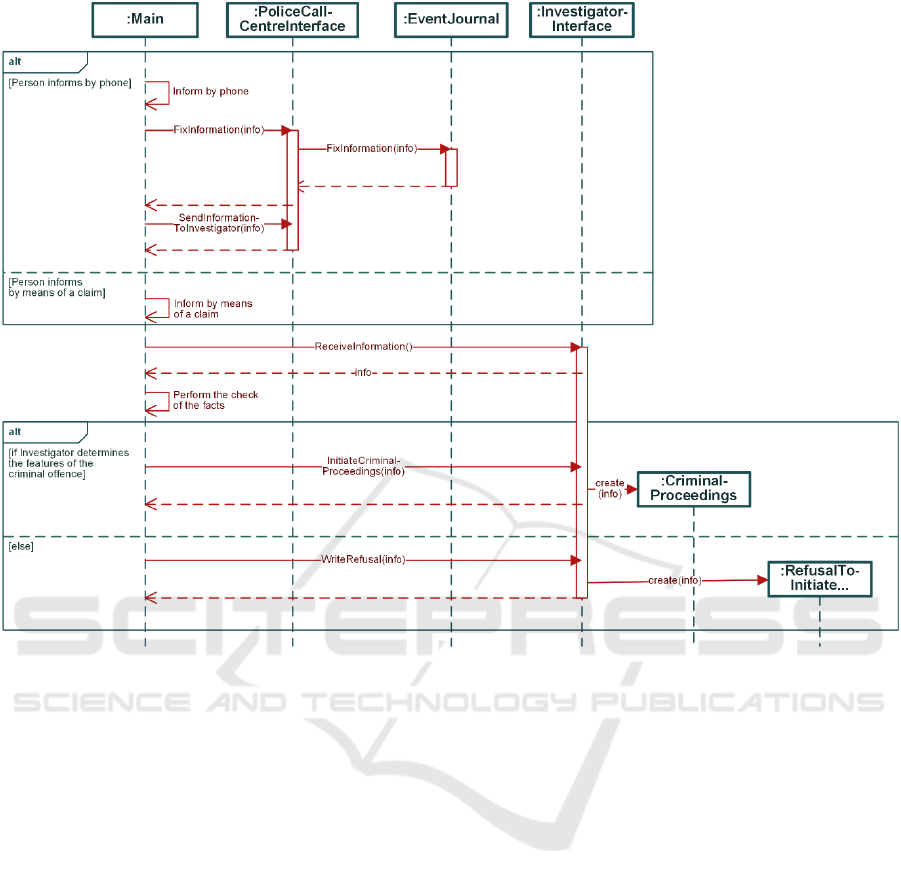
Figure 5: UML sequence diagram of the prototype of the application.
REFERENCES
Asnina, E. and Ovchinnikova, V., 2015. Specification of
decision-making and control flow branching in
Topological Functioning Models of systems. In ENASE
2015 - Proceedings of the 10th International Conference
on Evaluation of Novel Approaches to Software
Engineering. Lisbon: SciTePress, pp. 364–373.
Bhullar, N.S., Chhabra, B. and Verma, A., 2016. Exploration
of UML diagrams based code generation methods. In
2016 International Conference on Inventive
Computation Technologies (ICICT). IEEE, pp. 1–6.
Ciccozzi, F. et al., 2011. Generation of correct-by-
construction code from design models for embedded
systems. In 2011 6th IEEE International Symposium on
Industrial and Embedded Systems. IEEE, pp. 63–66.
Egea, M. and Dania, C., 2017. SQL-PL4OCL: An Automatic
Code Generator from OCL to SQL Procedural Language.
In 2017 ACM/IEEE 20th International Conference on
Model Driven Engineering Languages and Systems
(MODELS). IEEE, pp. 54–54.
Guana, V., Gaboriau, K. and Stroulia, E., 2014.
ChainTracker: Towards a Comprehensive Tool for
Building Code-Generation Environments. In 2014 IEEE
International Conference on Software Maintenance and
Evolution. IEEE, pp. 613–616.
Hili, N., Dingel, J. and Beaulieu, A., 2017. Modelling and
Code Generation for Real-Time Embedded Systems with
UML-RT and Papyrus-RT. In 2017 IEEE/ACM 39th
International Conference on Software Engineering
Companion (ICSE-C). IEEE, pp. 509–510.
M T, C. and Sherly, E., 2014. Refactoring sequence diagrams
for code generation in UML models. In 2014
International Conference on Advances in Computing,
Communications and Informatics (ICACCI). IEEE, pp.
208–212.
Miller, J. and Mukerji, J., 2001. Model Driven Architecture
(MDA).
Nazaruka, E., 2017. Meaning of cause-And-effect relations
of the topological functioning model in the UML analysis
model. In ENASE 2017 - Proceedings of the 12th
International Conference on Evaluation of Novel
Approaches to Software Engineering.
Nazaruka, E. et al., 2016. Verification of BPMN Model
Functional Completeness by using the Topological
Functioning Model. In Proceedings of the 11th
International Conference on Evaluation of Novel
Vision of the TFM-driven Code Acquisition
623

Software Approaches to Software Engineering. Portugal:
SCITEPRESS - Science and Technology Publications,
pp. 349–358.
Nazaruks, V., 2017. The Knowledge Frame System based on
Principles of Topological Functioning Model. Applied
computer systems, 21, pp.28–37.
Noyer, A. et al., 2014. Tool independent code generation for
the UML closing the gap between proprietary models and
the standardized UML model. In 2014 9th International
Conference on Evaluation of Novel Approaches to
Software Engineering (ENASE). IEEE, pp. 1–9.
Osis, J., 1969. Topological Model of System Functioning (in
Russian). Automatics and Computer Science, J. of
Academia of Sciences, (6), pp.44–50.
Osis, J. and Asnina, E., 2011. Topological Modeling for
Model-Driven Domain Analysis and Software
Development : Functions and Architectures. In Model-
Driven Domain Analysis and Software Development.
Hershey, PA: IGI Global, pp. 15–39.
Osis, J. and Donins, U., 2017. Topological UML modeling:
an improved approach for domain modeling and
software development, Elsevier.
Ovchinnikova, V. and Nazaruka, E., 2016. The Validation
Possibility of Topological Functioning Model using the
Cameo Simulation Toolkit. In Proceedings of the 11th
International Conference on Evaluation of Novel
Software Approaches to Software Engineering.
SCITEPRESS - Science and Technology Publications,
pp. 327–336.
Shiferaw, M.K. and Jena, A.K., 2018. Code Generator for
Model- Driven Software Development Using UML
Models. In 2018 Second International Conference on
Electronics, Communication and Aerospace Technology
(ICECA). IEEE, pp. 1671–1678.
Wang, B., Rosenberg, D. and Boehm, B.W., 2017. Rapid
realization of executable domain models via automatic
code generation. In 2017 IEEE 28th Annual Software
Technology Conference (STC). IEEE, pp. 1–6.
Wang, Y. et al., 2010. An approach of code generation based
on Model Integrated Computing. In 2010 International
Conference on Computer Application and System
Modeling (ICCASM 2010). Taiyuan: IEEE, pp. V15-114-
V15-117.
APPENDIX
public class CP {
public static Integer
AskNextStep(Map<Integer, String> steps) {
System.out.println("Next step:");
for (Integer step : steps.keySet()) {
System.out.println(" * " + step + ". "
+ steps.get(step)); }
Integer nextStep;
Scanner in = new Scanner(System.in);
do { nextStep = in.nextInt(); } while
(!steps.containsKey(nextStep));
return nextStep; }
public static void main(String[] args) {
Map<Integer, String> choice1 = new
HashMap<Integer, String>();
choice1.put(2, "Informing by phone…");
choice1.put(3, "Informing by claim…");
Map<Integer, String> choice2 = new
HashMap<Integer, String>();
choice2.put(7, "Initiating…");
choice2.put(8, "Writing a refusal…");
String info = "Information…";
switch (AskNextStep(choice1)) {
case 2:
PoliceCallCentreInterface.
FixInformation(info);
PoliceCallCentreInterface.
SendInformationToInvestigator(info);
break;
case 3: break; }
info = InvestigatorInterface.
ReceiveInformation();
switch (AskNextStep(choice2)) {
case 7: InvestigatorInterface.
InitiateCriminalProceedings(info);
break;
case 8:
InvestigatorInterface.
WriteRefusal(info); break; } } }
public class PoliceCallCentreInterface {
public static void FixInformation(String
info) { EventJournal.FixInformation(info);
}
public static void
SendInformationToInvestigator(String info)
{ }}
public class EventJournal {
public static void FixInformation(String
info) { }}
public class InvestigatorInterface {
public static String ReceiveInformation()
{ return "Information…"; }
static void
InitiateCriminalProceedings(String info) {
CriminalProceedings CP = new
CriminalProceedings(info); }
static void WriteRefusal(String info) {
RefusalToInitiateCP R = new
RefusalToInitiateCP (info); } }
public class CriminalProceedings {
public CriminalProceedings(String info)
{}}
public class RefusalToInitiateCP {
public RefusalToInitiateCP(String info)
{}}
MDI4SE 2019 - Special Session on Model-Driven Innovations for Software Engineering
624
