
Geometric Adaptive Robust Sliding-mode Control on SO(3)
Yulin Wang
a
, Xiao Wang
b
, Shengjing Tang
c
and Jie Guo
d
School of Aerospace and Engineering, Beijing Institute of Technology, Beijing, China
Keywords: Geometric Attitude Control, SO(3), Adaptive Robust Control, Sliding-mode Control.
Abstract: This paper addresses the rigid body attitude tracking control on the manifold
SO(3)
. This modeling scheme
can avoid the singularity and ambiguity associated with local parameterization representations such as Euler
angles and quaternion. A robust and almost global asymptotic stability control system is designed considering
the parameters uncertainty and external interference. Based on the coordinate-free geodesic attitude error
scalar function with its deduced attitude and velocity error vectors, a geometric asymptotic convergent sliding-
mode surface is designed firstly. Then, a geometric sliding-mode controller is introduced to enhance the
robustness of the system for the low-amplitude fast-time-varying disturbances. Moreover, in order to attenuate
the effect of the parameters uncertainty and slow-time-varying disturbance, two adaptive functions are
employed to obtain the feedforward compensation. Comparison studies and simulation results show that the
proposed controller is more practical with a high accuracy, strong robustness, less chattering and simple
structure.
1 INTRODUCTION
The movement of a rigid body in a three-dimensional
space can be divided into the movement in
translational space and the movement in rotational
space. The rotation control is usually the basis of the
translation control for most rigid bodies. For example,
in astronautics, the control forces of the satellite or
missile are mainly produced by the thrusters. In
aeronautics, the control forces of the aircraft or
quadrotor are mainly produced by their wings and
propellers. They are all executed based on the
maneuver of a rigid body’s orientation and rotation.
Therefore, the rigid-body attitude control has been
studied and applied extensively in many areas
recently, such as aerial vehicles, spacecraft vehicles,
underwater vehicles, ground vehicles, and robotics
(Islam et al., 2017; Forbes, 2014; Zlotnik and Forbes,
2014).
The orientation of the rigid body in a three-
dimensional space can be uniquely described by a
directional cosine matrix, which is the element of the
Lie group
SO(3)
(three-dimensional special
a
https://orcid.org/0000-0003-2666-836X
b
https://orcid.org/0000-0002-7583-7628
c
https://orcid.org/0000-0003-4224-9579
d
https://orcid.org/0000-0003-0951-5126
orthogonal group).
SO(3)
is also a nonlinear
differentiable manifold with nine elements and six
constraints. It is hard to analyze the geometric and
algebra properties of SO(3) using the method in
Euclidean space, which will be detailed later.
Therefore, local parameterizations of
SO(3)
were
mainly studied historically. However, all minimal
parameter presentations, such as Euler angle,
Rodrigues parameters and modified Rodrigues
parameters, are local and suffer from singularities.
Quaternions consisting of four parameters do not have
singularities but have ambiguities. It suffers from the
unwinding phenomena. Because the three-
dimensional sphere
3
double covers
SO(3)
. In
order to avoid the singularities and ambiguities in
representing an attitude, the controllers using
SO(3)
directly in a coordinate-free format have been
developed in recent years (Lee, Leoky and
Mcclamroch, 2011; Liu et al., 2016; Maithripala and
Berg, 2015).
The early results of nonlinear differentiable
manifolds are studied in (Boothby, 2003), where the
328
Wang, Y., Wang, X., Tang, S. and Guo, J.
Geometric Adaptive Robust Sliding-mode Control on SO(3).
DOI: 10.5220/0007917003280338
In Proceedings of the 16th International Conference on Informatics in Control, Automation and Robotics (ICINCO 2019), pages 328-338
ISBN: 978-989-758-380-3
Copyright
c
2019 by SCITEPRESS – Science and Technology Publications, Lda. All rights reserved

differential and integration properties, the tensor and
tensor field on Riemannian manifolds are derived.
Koditschek (Koditschek, 1988) designed the PD
based controller on SO(3), where the almost globally
asymptotically stability of the closed-loop system is
proved. Bullo (Bullo and Murray, 1999) proposed a
unified framework to design the controller for the
mechanical systems modeled on nonlinear manifolds,
such as
2
,
SO(3)
and
SE(3)
. For
SO(3)
, it is
also a Lie group with its compatible group operation
and zero element. Using the left-invariant property of
Lie group, the attitude and velocity error vectors can
be translated into its Lie algebra space, which is
diffeomorphism to
3
(Bullo and Murray, 1995;
Bullo and Murray, 1999; Maithripala and Berg, 2015).
Then, the vector operations addition and subtraction
can be used again in this case. Employing these
properties, Lee (Taeyoung, 2012; Lee, 2012; Lee,
2008) designed some specific attitude error scalar
functions on
SO(3)
, and based on these attitude
error scalar functions, the matching attitude
controllers are designed.
However, the existing attitude controllers on
SO(3)
are almost all designed based on the standard
augmented PD control with a feedforward
compensation loop (Bullo and Lewis, 2005; Lee,
2008; Lee et al., 2011). Besides, all those control laws
are designed based on the assumptions that the model
is precisely modeled in advance and there is no
external disturbance. The controllers above for a
perfect attitude tracking can not be realized in practice
due to the ideal assumptions. One feasible way to
solve this problem is designing an adaptive robust
controller (ARC) to estimate the uncertain inertial
matrix and constant external disturbances (Fernando
et al., 2011; Sanyal et al.; 2009). However, these
adaptive controllers do not consider the time-varying
disturbances. The sliding-mode controller (SMC) can
deal with all bounded disturbances (Liu et al., 2016).
However, SMC will cause a heavy chattering
phenomenon for the high-amplitude disturbances,
which might be dangerous in practice.
Combined with the virtues of ARC and SMC, the
adaptive robust sliding-mode controller (ARSMC)
can handle these problems efficiently (Islam et al.,
2017). However, the ARSMC is hard to apply to a
nonlinear manifold and its tangent space. As the
attitude error vector of nonlinear manifold is deduced
from the error scalar function (Bullo and Murray,
1999). The error dynamics of nonlinear manifolds are
not only determined by the topology structure of the
manifold generally, but also related to the choice of
the error scalar function. For the closed compact
manifolds which are not diffeomorphism to any
Euclid space, such as these familiar nonlinear
manifolds
2
,
3
,
SO(3)
and
SE(3)
, the
magnitude of the attitude error vector designed in
(Bullo and Murray, 1999; Bullo and Lewis, 2005) will
decrease to zero at each isolated critical points.
Therefore, the conventional design process of the
asymptotically convergent sliding-mode surface,
which will let the attitude error vector converge to
zero, are infeasible. Moreover, the time derivative of
the attitude error vector is not equal to and even not
positively related to the velocity error vector. The
relationship between these two error vectors is often
ambiguous which is determined by the choice of the
attitude error scalar function. For
SO(3)
, the time
derivative of the attitude error vector can be expressed
as a three-dimensional intermediate variable matrix
33
E
multiples the velocity error vector (Lee,
2012). However, the eigenvalues of the matrix
E
may be indefinite, which are also determined by the
choice of the error scalar function. All those
properties above lead to the failure of the methods
used in Euclid space. Therefore, The ARSMC has
never been applied to the attitude control of a rigid
body modeled on SO(3).
Following the geometric control approaches of the
prior arts, a geometric adaptive robust sliding-mode
controller (GARSMC) on
SO(3)
is designed in this
paper. The geometric asymptotically convergent
sliding-mode surface is designed firstly, where the
geometric properties of the error scalar function
proposed in (Lee, 2012) and its deduced attitude and
velocity error vectors are applied. Moreover, an
exponential reaching law is adopted to stabilize the
closed-loop system. In order to facilitate the
controller design, the unknown external disturbance
torque in the body-fixed frame is divided into the
high-amplitude slow-time-varying part and the low-
amplitude fast-time-varying part. Then, the adaptive
functions for the uncertain inertial matrix and the
unknown high-amplitude slow-time-varying
disturbances are designed, respectively. Moreover,
the low-amplitude high-frequency disturbances,
which can not be estimated rapidly by the adaption
function, can be dealt with by the geometric sliding-
mode control (GSMC) part with small switching term
amplitudes which can also suppress the undesired
chattering.
Compared with the prior ARC in (Fernando et al.,
2011; Sanyal et al., 2009), the proposed adaptive
controller part has a simpler structure with less
computation costs. Compared with the prior SMC in
(Liu et al., 2016), the proposed controller also has a
Geometric Adaptive Robust Sliding-mode Control on SO(3)
329

simpler sliding-mode surface and less chattering.
Besides, the proposed controller can be used to handle
a more general class of unconstructed and non-
harmonic uncertainties than the prior works
(Fernando et al., 2011; Lee, 2012; Liu et al., 2016;
Sanyal et al., 2009). Numerical simulations results
shows that the proposed controller has a strong anti-
interference ability compared with the PD-based
controller (Lee, 2012) and ARC, and less chattering
phenomenon compared with SMC. The topology
structure of compact manifold precludes the existence
of a smooth global asymptotic stabilization control
(Bhat and Bernstein, 2000). However, using
Lyapunov stability theory, the almost global
asymptotic stability can be proved for the proposed
controller. The convergent region of the unique stable
point covers SO(3) but only excludes a set of zero
measure critical points. Simulation results illustrate
the effectiveness of the proposed controller.
The paper is organized as follows. The attitude
dynamic model of a rigid body is developed in section
2. The attitude error scalar function and its deduced
attitude error dynamics are analyzed in section 3. The
proposed geometric adaptive robust sliding-mode
controller is designed in section 4. The numerical
simulation follows in section 5. Section 6 summarizes
the results and conclusions of this paper.
2 MODELING
The kinematics and dynamics of a rigid body’s
rotation movement in a three-dimensional Euclidean
space are considered in this section. The earth-fixed
coordinate is defined as the inertial reference frame,
and the body-fixed frame is defined attached to the
rigid-body’s mass center. The rigid-body attitude
kinematics and dynamics equations can be described
as (Bullo and Murray, 1995),
=
RRΩ
JΩΩJΩ ud
(1)
where
3
Ω
is the angular velocity with respect to
the body-fixed frame. The rotation matrix
SO(3)
R
represents the direction cosine matrix (DCM) from
the body-fixed frame to the inertial reference frame.
The attitude
R
of the nonlinear manifold
SO(3)
satisfies
33 T
SO(3)= | ,det 1
RRRIR
(2)
33
J
is the inertial matrix.
3
u
is the
control torque.
3
d
is the disturbance defined in
the body-fixed frame. It consists of the high-
amplitude slow-time-varying disturbances
0
d
and
the low-amplitude fast-time-varying disturbances
1
d
,
which satisfies
01
dd d
(3)
0
d
is mainly caused by the deviation of the mass
center of the rigid body.
1
d
is mainly caused by the
unknown friction force, such as the air drag for
quadrotor , and randomly external interferences, such
as random wind for aircraft. The isomorphism hat
map
3
:so(3)
denotes a skew-symmetric
matrix operation which can be defined as
32
31
21
0
=0
0
Ω
(4)
where
so(3)
is the Lie algebra. The inverse of the
hat map is denoted by the vee map
3
:so(3)
.
For any
3
, xy
,
33
A
and
SO(3)R
, it
can be proved easily that several properties of the hat
map and the vee map are satisfied as follows (Lee,
2012):
TTT
1
2
T
tr tr
=tr
=
T
xy x y y x yx
Ax x A A x A A
xA Ax AI Ax
Rx R Rx
(5)
3 ERROR DYNAMICS
The twice differentiable desired attitude trajectory is
denoted by
SO(3)
d
t R
. What we need to do is
designing a control law
3
u to track
d
tR
,
considering the existence of the parameters
uncertainties and external disturbance. The
kinematics equation of the desired trajectory can be
written as
=
T
ddd
Ω
R
R
(6)
where
3
d
Ω
is the desired angular velocity with
respect to the body-fixed frame.
3.1 Assumptions
The following conditions are assumed.
ICINCO 2019 - 16th International Conference on Informatics in Control, Automation and Robotics
330
1. The inertial matrix
J
of a rigid body is
regarded as a constant diagonal matrix, which
is
123
diag( )JJJJ
(7)
J
cannot be acquired precisely in advance.
However
J
is bounded with the known bounds as
0
mM
J
JJ
(8)
where
m
J
and
M
J
are two known constant
diagonal matrix.
2. The slow-time-varying disturbances
0
d
and
fast-time-varying disturbances
1
d
are
bounded with two known constant array
3
0
D
and
3
1
D
respectively as
00
11
dD
dD
(9)
3. The desired attitude trajectory is smooth and
bounded.
3.2 Attitude Error Dynamics
The topological structures and geometric properties
of nonlinear differentiable manifolds are quite
different from those of the classical mechanics in
Euclidean space (Boothby, 2003; Bhat and Bernstein,
2000). Before the controller is designed, the
geometric attitude tracking error and its compatible
zero element should be defined firstly. The geometric
tracking error between
tR
and
d
tR
are
defined as
SO(3)
T
ed
RRR
. The zero element of
e
R
is the three-dimensional identity matrix (Bullo
and Murray, 1999; Maithripala and Berg, 2015).
For a given attitude tracking command
,
dd
R Ω
,
a smooth geodesic attitude error scalar function
:SO(3) SO(3)
is defined as (Lee, 2012)
=, 21tr()
T
dd
ttt
R
RRR
(10)
It can be proved from (Lee, 2012)that the
following properties are satisfied for any
d
R
and
R
:
i.
,0
d
RR
.
ii.
,=0
d
RR
if and only if
=
d
R
R
.
iii. The error scalar function
is symmetric
with
,= ,
dd
R
RRR
.
The attitude error scalar function
gets its
unique global minimum
0
at
d
R
R
. It
provides a measurement for the magnitude of the
tracking error between the two attitudes
R
and
d
R
to some extent. Except for
d
R
R
, the attitude error
scalar function
has some other critical points,
which are determined by the topology of
SO(3)
and
corresponds to the global maximum point of function
. These isolated critical points are also the local
equilibrium points of the closed loop system.
Therefore, it is impossible to find a globally stable
continuous feedback controller on
SO(3)
and only
the almost global stability can be achieved for the
closed-loop system (Bhat and Bernstein, 2000).
Using the properties in (5), the time derivative of
e
R
can be deduced as (Lee, 2012)
d
d
T
ee dd
t
RRΩ RRΩ
(11)
Furthermore, the time derivative of the error scalar
function
can be obtained as
d
,
d
1
21 tr( )
d
TT T
dd dd
T
d
tt
t
RR
RRRR Ω RR
Ω
RR
(12)
According to the geometric description of the
attitude and velocity error vectors proposed in (Bullo
and Murray, 1999) and the properties of the Lie group
SO(3) in (Maithripala and Berg, 2015), an attitude
error vector
R
e
can be defined as the partial
differential of
with respect to
R
, which are
expressed as
d
1
,
21 tr( )
TT
Rdd
T
d
eRR RRRR
R
RR
(13)
where
R
e
is the gradient of the error scalar function
at its current attitude point
R
. To make the
denominator in (13) non-zero, the attitude error vector
R
e
must be defined in the sublevel set
d
=SO(3), 2L
RRR
.
Furthermore, according to the geometric
description in (Maithripala and Berg, 2015) and using
the left-invariant properties of Lie group, the velocity
error vector
e
can be defined as
,= =
TT
dee dd
tt
Ω
eR R RR Ω RR
Ω
(14)
Then, the time derivative of the error scalar
function
can be rewritten as the equation in (15),
Geometric Adaptive Robust Sliding-mode Control on SO(3)
331
which is similar to the properties and relationships
between the location and velocity error vectors used
in three-dimensional Euclid space.
d
,
d
d
tt
t
R Ω
R
Ree
(15)
Notice that
3
,
R Ω
ee
do not live on the
cotangent bundle
*
SO(3)T
R
or the tangent bundle
SO(3)T
R
. Because the properties of the Lie group and
Lie algebra are used here. The precise but
complicated statement for the attitude and velocity
error vectors are
*
SO(3)T
RR
Re
and
SO(3)T
Ω R
Re
respectively (Bullo and Murray,
1999; Maithripala and Berg, 2015).
Furthermore, the attitude error dynamics are
obtained as
R Ω
eEe
(16)
1
0
+++
d
Ω
eJ Ω JΩ ud d α
(17)
where
33
E
and
3
d
α
are given as
T
1
tr 2
21 tr( )
TT
dd
T
d
RR
E
RR I RR ee
RR
(18)
TT
ddd dd
α RRΩΩRRΩ
(19)
It can be seen that
E
is a variable matrix
related to
e
R
. In order to analysis the algebra
properties of
E
, we use the Rodrigues formula here
as follows (Lee, 2012). For any L
Q , there exists
a vector
3
x
with
x
, such that
2
2
sin 1 cos
exp
xx
QxI x x
x
x
(20)
x
is the Rodrigues formula expression of L
Q
and satisfies
x
.
exp : so 3 SO(3)
is the
exponential map. The inverse of the exponential map
can be defined as
log: SO(3) so 3
, which can be
expressed by
T
2sin
xRR
(21)
where the variable
is given by
1
cos tr 1 ,
2
R
(22)
With (20), the eigenvalues of matrix
Q can be
calculated as
1, cos sin , 1, 2, 3
j
Q
ij
xx
(23)
Let
e
QR
and substituting (20) and (23) into
the formula of matrix
E
in (18), we can also get that
the eigenvalues of matrix
E
are (Liu et al., 2016)
11
cos , cos sin
222 2 2
j
E
i
xxx
(24)
Furthermore, the determinant value of the matrix
E
, are
3
1
1
det cos
82
j
E
j
x
E
(25)
Since
x
, it can be concluded that matrix
E
is a positive definite and nonsingular matrix.
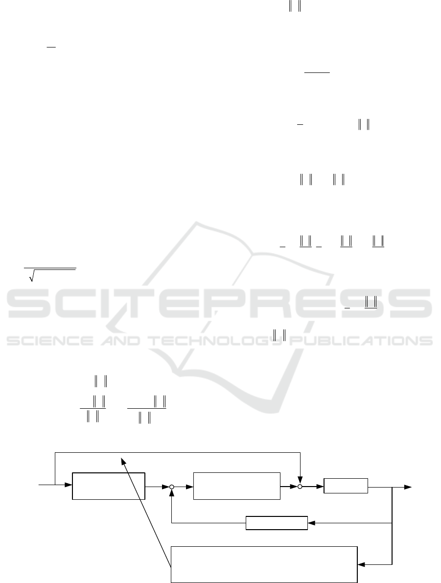
4 CONTROLLER DESIGN
This section mainly introduces a geometric adaptive
robust sliding-mode attitude tracking controller on
SO(3)
. The control architecture is shown in Fig 1.
0
s
ˆ
ˆ
ˆ
dR
Ω JΩ d
J α KEe
a
u
d
R
s
R
eKe
Model compensation for
perfect tracking
Sliding surface
sgnKs H s
Sliding-mode feedback control
s
0
0
T
ˆ
=
ˆ
d
Jds
diag diag diag
dTs
JT Ms s α KEe
Adaptive rate with projection mapping
u
0
ˆ
ˆ
,dJ
,R
Ω
ˆ
=
RRΩ
JΩΩJΩ ud
The rigid body
s
u
Figure 1: The structure of the proposed control system.
ICINCO 2019 - 16th International Conference on Informatics in Control, Automation and Robotics
332

The controller mainly consists of two parts. The
feedforward model compensation part which contains
the adaption functions for the unknown parameters or
slow-time-varying disturbance, and the variable
structure feedback part. Both of them are designed
based on the geometric sliding-mode surface
s
.
Therefore, we need to design a geometric
asymptotically convergent sliding-mode surface
firstly.
4.1 The Design of the Geometric
Sliding-mode Surface
As the attitude vector
R
e
and the velocity vector
Ω
e
belong to the same space
3
, the vector
operations, such as addition, subtraction and matrix
multiplication, in Euclidean space can be used in this
case. Then, the asymptotically convergent sliding-
mode surface
T
123
s
tstst
s
is
introduced as
s
R
se Ke
(26)
where
33
s
K
is a constant positive definite
diagonal matrix. The minimum eigenvalue of
s
K
should be designed greater than or equal to 1 / 4 and
the reason will be detailed later in the stability
analysis.
s
K
decides the convergence speed of
R
e
when the system reach on the sliding-mode surface
s0
. Substituting (16) to (26), we can get that
R
sR
eEKe
(27)
Integrating it, we can get that
= exp( d ) 0
RsR
t
eEKe
(28)
Since matrix
E
is positive definite. After the
system reach on the sliding-mode surface
s0
, the
attitude tracking error
R
e
will converge to its unique
stable equilibrium
0
R
e
exponentially.
4.2 Attitude Tracking Control
With the control architecture shown in Fig 1, the
geometric adaptive robust sliding-mode attitude
tracking control law
u
consisting of the
feedforward compensation part
a
u
and the variable
structure feedback part
s
u
is shown as
0s
ˆ
ˆ
ˆ
sgn
as
ad
s
uu u
u Ω JΩ dJα KEe
uKsH s
(29)
where
33
,
KH
are two constant positive
definite diagonal matrix. The function
sgn s
for
the sliding-mode surfaces are defined as
T
123
sgn( ) sign( ) sign( ) sign( )ssss
(30)
where
sign( )
is the sign function.
In (29),
a
u
is designed for a feedforward
compensation tracking through an online parameters
adaptive law
ˆ
J
and
0
ˆ
d
.
ˆ
J
and
0
ˆ
d
will be
designed in the next subsection.
s
u
is composed by
a nominal stabilizing feedback
Ks
and a robust
feedback
sgnHs
.
33
K
is a linear gain to
determine the reaching law.
33
H
is a parameter
to determine the robustness of this system. The
robustness is stronger with a larger
H
. However, the
inherent chattering phenomenon is more heavy with a
larger
H . H in this controller is designed as
1
HD
(31)
Remark 1:
a
u
contains the estimated values of
0
ˆ
d
and
ˆ
J
. Those model uncertainties and high-
amplitude slow-time-varying disturbances can be
estimated and compensated by this part. The low-
amplitude high-frequency disturbances, which can
not be estimated rapidly by the adaption functions,
can be resolved by the variable structure part with a
small switching term amplitude. The amplitude is
determined by the upper bounds of the low-amplitude
disturbance
1
D
. Therefore, the undesired chattering
can be suppressed efficiently.
4.3 Adaptive Law Design with
Projection Mapping and Rate
Limits
In the feedforward compensation part
a
u
, the
diagonal matrix
ˆ
J
represents the estimated value of
the rigid body’s inertial matrix.
0
ˆ
d
represents the
estimated value of the slow-time-varying disturbance.
The update laws of those two parameters are designed
as
0
0
ˆ
=
d
dTs
(32)
T
ˆ
diag diag diag
Jds
JT Ms s α KEe
(33)
Geometric Adaptive Robust Sliding-mode Control on SO(3)
333

where
33
M
is given as
23 23
13 13
12 12
0
0
0
M
(34)
M
satisfies the following equation
diagΩ JΩ
M
J
(35)
0
33
Jd
,TT
are two positive symmetric matrixes
to accelerate or decelerate the adaption speed of
ˆ
J
and
0
ˆ
d
.
In practice,
J
and
0
d
are usually bounded. To
avoid the oversize or undersize of the estimated
values
ˆ
J
and .
0
ˆ
d
, a widely used projection map
(Yao and Jiang, 2010; Yao et al., 2002) is used to keep
the parameter estimates within a known bound, which
is
T
ˆ
T
ˆ
ˆ
ˆ
T
ˆ
T
ˆˆ
ˆ
, int or 0
Proj
ˆ
(),and0I
θ
θ
θθ
θ
θθ
ζθΩn ζ
ζ
nn
θΩ n ζ
nn
(36)
where
m
θ
is the unknown parameter.
ˆ
θ
denotes the estimate value of
θ
.
m
ζ
is an
adaptive law for
θ
.
m
is the dimension of
θ
.
Ω
is the boundary of the unknown parameter
θ
,
and
int
Ω
denotes the interior of this known
boundary.
ˆ
θ
n
represents the outward unit normal
vector at
ˆ
θΩ
.
In order to limit the adaptive rate for the control
process, a saturation function with a pre-set value
M
θ
is defined as
,
sat
,
MM
M
M
θθ
ζ
ζζ
ζ
ζζ
(37)
The upper bound of the adaptive rate for
J
and
0
d
are represented as
M
J
and
0
M
d
, respectively.
Assuming that the uncertain estimate parameter
ˆ
θ
is updated using the projection mapping and the
saturation function defined above in (36) and (37), the
designed adaptive law can be modified as
ˆ
ˆˆ
=sat Proj 0 int
M
,
θ
θ
θθΩ
(38)
where
is the adaptive law proposed in (32) and
(33). According to (Yao and Tomizuka, 1996), the
following properties for the function in (38) can be
obtained as:
i.
The estimation values of
J
and
0
d
are
always within the known bounded set
int
ΩΩ
. Thus from assumption 1,
ˆ
mM
0J JJ
and
00
ˆ
dD
can be
always satisfied.
ii.
The adaptive rate is uniformly bounded by
ˆ
,
M
t
θθ
.
iii.
ˆ
ˆ
Proj 0,
θ
θθ τ τ τ
.
4.4 Stability Analysis
The inertial matrix estimation error
J
and slow-
time-varying disturbance estimation error
0
d
are
defined as
00 0
ˆ
=
ˆ
dd d
J
JJ
(39)
Theorem 1: With the control law (29), the adaption
functions (32) and (33), the equilibrium point
,,
R
ee 00
of the tracking errors is almost
global asymptotically stable, whose attraction region
is given as (40) and (41). Moreover, the two
estimation error
J
and
0
d
are bounded.
0, 0 2
d
RR
(40)
0min
-1
-1
00
11
00 0 0
22
1
+0 0 20
2
J
dK
sJs JTJ
dTd
(41)
where
min
K
is the minimal eigenvalue of matrix
K
.
Proof: A positive semi-definite Lyapunov function
candidate is constructed as follows
0
-1 -1
1
00
2
11
+
22
Jd
V
sJs JT J d T d
(42)
where
J
T
,
0
d
T
are defined in (32) and (33),
respectively. Compared with the dynamic
characteristics of system, the time derivative of the
slow-time-varying disturbance is small and close to
zero. Then, differentiating the Lyapunov function gets
that
0
-1 -1
00
ˆ
ˆ
+
Jd
V
J
ss JT J d T d
(43)
where the linear product “
” for the vectors and the
square matrixes are defined as (44), respectively.
ICINCO 2019 - 16th International Conference on Informatics in Control, Automation and Robotics
334

T3333
T3131
tr , ,
,,
AB AB A B
ab ab a b
(44)
The time derivative of the sliding-mode surface
s
is obtained as
1
10 ds
sJ Ω JΩ ud d α KEe
(45)
Substituting (35), (44), (45) into (43), with the
control law in (29) we can get
0
0
1
10
-1 -1
00
-1 -1
0 010
ˆ
ˆ
+
=sgndiag+
ˆ
ˆ
+
ds
Jd
ds
Jd
V
Js J Ω JΩ ud d α KEe
JT J d T d
sKsH sM JJα KEe
JT J d T d d d
(46)
Taking account of the adaptive law in (32-33) into
(46), it holds
1
1
=sgn
+
V
sKsH sd
sKs H s d s
(47)
H
is designed in (31) with
1
HD
.
1
d
is
assumed to be bounded by
1
D
with
1
dH0
as
shown in (9). Therefore the following inequality
always holds
0V
sKs
(48)
If and only if
=0s
,
=0V
. With the Barbalat
lemma, we can get
0s
with
t
. Moreover,
when
0s
is satisfied, the attitude tracking error
R
e
will converge to its unique stable equilibrium
0
R
e
exponentially.
To make the denominator in (13) non-zero, the
given condition
,
d
ttRR
should always lies in
the sublevel set
L
. Therefore, (40) is proven. In
order to prove (41), a new Lyapunov function is
defined as
min
2
,
K
d
VV
R
R
(49)
With the equations of (15) and (48), the time
derivative of
2
V
is formulated as
2
22
22
4
0
ss
s
V
R Ω
R Ω R Ω
RR
sKs e Ke
KI KI
ee K ee
Ι
eK e
(50)
s
K
is designed in (26). whose minimum eigenvalue
is not smaller than
14
. Equation (50) implies that
2
V
is non-increasing. Then, using (41), it holds that
min min
22
,02
Kd K
Vt V
RR
(51)
Therefore,
,2
d
RR
can be always hold.
Then, (41) is proven.
The attraction region described by (40) and (41)
almost covers
SO(3)
except a set of zero measure
critical points where
0, 0
d
RR
get its
maximum value
0, 0 2
d
RR
. However,
when the value of
0, 0
d
RR
is closed to 2
and the norms of
0
J
and
0
0
d
are also large,
the region of
0
Ω
e
calculated in (41) is small.
However, we can adjust the controller parameters
K ,
J
T
and
0
d
T
to enlarge the selection region of
0
Ω
e
such that (41) always holds.
As
0V
always hold, the Lyapunov function is
bounded, which can prove that the estimate error
J
and
0
d
are bounded. However the estimate error
may not converge to zero. From (32) and (33), it can
be gotten that if
0s
,
0
ˆ
d0
and
ˆ
J
0
.
Therefore
0
ˆ
d
,
ˆ
J
will not change at this time.
Therefore,
0
d
,
J
may not converge to zero.
However the convergences of
and
R
e
will not
be influenced.
5 SIMULATION
In this section, the comparative simulations are
carried out for the designed GARSMC, ARC, SMC,
and the augmented PD controller designed in (Lee,
2012). A quadrotor UAV is used as an example.
The initial attitude is fixed as
0
R
I
. The
desired attitude trajectory
d
tR
is described using
3-2-1 Euler angles which is
exp exp exp
dxyz
t
Rbbb
.
x
b
,
y
b
,
z
b
are three axes of the rigid body. The
Euler angles
,
,
represent roll, pitch and
yaw angles, respectively, which are given as shown in
Tab.1.
The information for the uncertain inertial matrix
Geometric Adaptive Robust Sliding-mode Control on SO(3)
335

and the external disturbances is setting as shown in
Tab.2. The parameters used in the control law and the
adaption function are given as shown in Tab.3.
Simulation results are presented in Figs 2-6.
Table 1: The desired Euler angles.
Euler angles Val ues
Roll
rad
= sin 2 +0.65tt
Pitch
rad
=+0.02tt
Ya w
rad
=sin3 0.65 tt
Table 3: Controller parameters.
Parameters Val ues
Controller
parameters
diag 20 20 20
diag 0.25 0.25 0.25
s
K
K
Amplification
coefficient for the
adaption function
0
diag333
diag 1 1 1
d
J
T
T
Maximal adaptive
law
0
=5
=0.1
M
d
M
J
In Fig 2, the responses of the proposed GARSMC
are compared with those in ARC, SMC and geometric
PD
controller. It has been shown that the tracking errors
and
R
e
of the geometric PD controller do not
converge to zero with the influences of disturbances
and parameter uncertainties. However, these
characteristics are significantly improved by using the
GARSMC. It also can be seen that the proposed
GARSMC has higher control accuracy than ARC.
SMC has the same accuracy as the GARSMC.
However, Fig 3 shows that there exists a heavy
chattering in SMC. Even though, the saturation
function is used to eliminate the undesired chattering.
Therefore, the proposed GARSMC can achieve a high
accuracy with a strong robustness, and it can also
eliminate the chattering phenomenon efficiently.
Fig 4 shows the history of the estimate values of
the fixed disturbances
0
d
and the inertial matrix
J
under the GARSMC. It can be observed that the
inertial matrix and fixed disturbance will not
converge to their true value. However, it can be shown
in Fig 2 that the system stability and control precision
are not influenced.
Fig 5 shows the information of the sliding-mode
surface. It can be seen from Fig 5.(b) that the system
will converge to the sliding-mode surface
s0
firstly at
0.22ts
, and then converge to its stable
point
R
e0
,
Ω
e0
along the sliding-mode
surface
s0
. Fig 5.(b) shows that the inherent
chattering phenomenon under the GARSMC is
suppressed significantly compared with SMC.
In order to illustrate the almost global
convergence of the closed-loop system controlled by
the GARSMC, the orientation maneuvers of
spacecraft's body axes
2
b
is depicted in Fig 6. The
direction of rotation is marked with two red arrows. It
can be seen that the closed-loop system controlled by
the GARSMC can achieve the large-angle maneuver
(greater than / 2
rad) without singularity and
unwinding.
Table 2: Information for inertial matrix and disturbances.
Inertial matrix
2
kg m
Fixed disturbances
Nm
Time-varying disturbances
Nm
Real values
diag(0.009 0.009 0.017) J
0
0.8
=0.8
0.5
d
1
0.25sin 0.5
=0.2sin2 0.5
0.15sin
t
t
t
d
Initial
estimated
values
ˆ
0 diag 0.015 0.015 0.025 J
0
0
ˆ
0=0
0
d
--
Bounds
diag 0.005 0.005 0.010
diag 0.02 0.02 0.03
m
M
J
J
0
1
=1
1
D
1
0.3
=0.3
0.3
D
ICINCO 2019 - 16th International Conference on Informatics in Control, Automation and Robotics
336
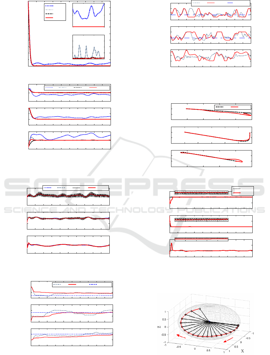
(a) Attitude error scalar function
(rad)
(b) Attitude error vector
R
e
(rad)
Figure 2: Attitude tracking.
Figure 3: The control input (Nm).
(a) Estimatedfixeddisturbances
0
ˆ
d
(Nm)
(b) Estimated inertial matrix
ˆ
J
(kg m
2
)
Figure 4: Estimate values of the parameters.
(a) Phase portrait
(b) Sliding-mode variables
s
(rad)
Figure 5: Sliding-mode surface.
Figure 6: Orientation maneuver of
2
b
.
0 0.5 1 1.5 2 2.5 3 3.5 4 4.5 5
0
0.2
0.4
0.6
0.8
1
1.2
1.4
1.6
1.8
2
t
(s)
φ
xL
PD
ARC
SMC
GARSMC
2 3 4 5
0
0.05
0.1
2 3 4 5
0
1
2
3
4
x 10
-4
0 0.5 1 1.5 2 2.5 3 3.5 4 4.5 5
-0.5
0
0.5
PD ARC SMC GARSMC
0 0.5 1 1.5 2 2.5 3 3.5 4 4.5 5
-0.5
0
0.5
1
e
R
0 0.5 1 1.5 2 2.5 3 3.5 4 4.5 5
-0.2
0
0.2
t
(s)
0 0.5 1 1.5 2 2.5 3 3.5 4 4.5 5
-5
0
5
PD ARC SMC GARSMC
0 0.5 1 1.5 2 2.5 3 3.5 4 4.5 5
-10
-5
0
5
u
0 0.5 1 1.5 2 2.5 3 3.5 4 4.5 5
-5
0
5
t
(s)
0 0.5 1 1.5 2 2.5 3 3.5 4 4.5 5
-1
-0.5
0
0.5
ARC GARSMC Real V alues
0 0.5 1 1.5 2 2.5 3 3.5 4 4.5 5
0
0.5
1
1.5
d
0
0 0.5 1 1.5 2 2.5 3 3.5 4 4.5 5
-0.5
0
0.5
1
t
(s)
0 0.5 1 1.5 2 2.5 3 3.5 4 4.5 5
0
0.01
0.02
0.03
J
xx
ARC GARSMC Real Values
0 0.5 1 1.5 2 2.5 3 3.5 4 4.5 5
0
0.01
0.02
0.03
J
yy
0 0.5 1 1.5 2 2.5 3 3.5 4 4.5 5
0
0.01
0.02
0.03
J
zz
t
(s)
-0.05 0 0. 05 0.1 0.15 0.2
-10
-5
0
5
SMC GARSMC
-0.2 0 0.2 0.4 0. 6 0.8 1
-20
-10
0
10
e
(rad/s)
-0.2 -0.15 -0.1 -0.05 0 0.05
-2
0
2
4
e
R
(rad)
0 0.5 1 1.5 2 2.5 3 3.5 4 4.5 5
-4
-2
0
2
SMC
GARSMC
0 0.5 1 1.5 2 2.5 3 3.5 4 4.5 5
-10
0
10
20
s
0 0.5 1 1.5 2 2.5 3 3.5 4 4.5 5
-0.5
0
0.5
1
t
(s)
4.6 4.62 4.64 4.66 4.68 4. 7
-0.1
0
0.1
4.6 4.62 4.64 4.66 4.68 4. 7
0
0.05
0.1
4.6 4.62 4.64 4.66 4.68 4. 7
-0.05
0
0.05
Geometric Adaptive Robust Sliding-mode Control on SO(3)
337

6 CONCLUSIONS
This paper addresses the rigid-body attitude control
modeled on the manifold
SO(3)
. This modeling
scheme can avoid the singularities and ambiguities
appearing in Euler angles and quaternion, respectively.
The definitions and the algebra properties of the
attitude error scalar function, attitude and velocity
error vector on
SO(3)
are introduced firstly. Then,
a geometric asymptotical convergent sliding mode
surface is designed based on these properties.
Furthermore, a geometric adaptive robust sliding-
mode attitude tracking controller system is developed
to track the desired attitude command, considering the
external interferences and model uncertainty. The
values of the unknown inertial matrix and slow-time-
varying disturbance are estimated online by the
adaption functions. The fast-time-varying disturbance
is dealt with by the variable structure part.
Comparative simulation results demonstrate the high
precision, strong robustness and little chattering of the
proposed controller.
ACKNOWLEDGEMENTS
This work is supported by the National Natural
Science Foundation (NNSF) of China under Grant
11572036.
REFERENCES
Bhat, S. P. & D. S. Bernstein (2000) A topological
obstruction to continuous global stabilization of
rotational motion and the unwinding phenomenon.
Systems & Control Letters, 39, 63-70.
Boothby, W. M. 2003. An introduction to differentiable
manifolds and Riemannian geometry. Amsterdam; New
York: Academic Press.
Bullo, F. & A. D. Lewis. 2005. Geometric Control of
Mechanical Systems. Springer.
Bullo, F. & R. M. Murray. 1995. Proportional Derivative
(PD) Control on the Euclidean Group. In European
Control Conference, 1091--1097.
Bullo, F. & R. M. Murray (1999) Tracking for fully actuated
mechanical systems: a geometric framework.
Automatica, 35, 17-34.
Fernando, T., J. Chandiramani, T. Lee & H. Gutierrez. 2011.
Robust adaptive geometric tracking controls on SO(3)
with an application to the attitude dynamics of a
quadrotor UAV. In Decision and Control and European
Control Conference, 7380-7385.
Forbes, J. R. (2014) Passivity-Based Attitude Control on the
Special Orthogonal Group of Rigid-Body Rotations.
Journal of Guidance Control & Dynamics, 36, 1596-
1605.
Islam, S., P. X. Liu & A. E. Saddik (2017) Nonlinear robust
adaptive sliding mode control design for miniature
unmanned multirotor aerial vehicle. International
Journal of Control Automation & Systems, 15, 1-8.
Koditschek, D. E. 1988. Application of a new Lyapunov
function to global adaptive attitude tracking. In
Decision and Control, 1988., Proceedings of the IEEE
Conference on, 63-68 vol.1.
Lee, T. (2008) Computational geometric mechanics and
control of rigid bodies. Dissertations & Theses -
Gradworks.
Lee, T. (2012) Exponential stability of an attitude tracking
control system on SO(3) for large-angle rotational
maneuvers ☆. Systems & Control Letters, 61, 231-237.
Lee, T., M. Leoky & N. H. Mcclamroch. 2011. Geometric
tracking control of a quadrotor UAV on SE(3). In
Decision and Control, 5420-5425.
Liu, J. T., W. H. Wu, J. Li & Q. Xin (2016) Sliding mode
variable structure attitude controller design of quadrotor
UAVs on SO(3).
Maithripala, D. H. S. & J. M. Berg. 2015. An intrinsic PID
controller for mechanical systems on Lie groups.
Pergamon Press, Inc.
Sanyal, A., A. Fosbury, N. Chaturvedi & D. S. Bernstein.
2009. Inertia-free spacecraft attitude trajectory tracking
with internal-model-based disturbance rejection and
almost global stabilization. In Conference on American
Control Conference, 4830-4835.
Taeyoung, L. 2012. Robust global exponential attitude
tracking controls on SO(3). In American Control
Conference, 2103-2108.
Yao, B., F. Bu, J. Reedy & T. C. Chiu (2002) Adaptive
robust motion control of single-rod hydraulic actuators:
theory and experiments. IEEE/ASME Transactions on
Mechatronics, 5, 79-91.
Yao, B. & C. Jiang. 2010. Advanced motion control: From
classical PID to nonlinear adaptive robust control. In
IEEE International Workshop on Advanced Motion
Control, 815-829.
Yao, B. & M. Tomizuka. 1996. Smooth robust adaptive
sliding mode control of manipulators with guaranteed
transient performance. In American Control Conference,
1176-1180 vol.1.
Zlotnik, D. E. & J. R. Forbes. 2014. Rotation-matrix-based
attitude control without angular velocity measurements.
In American Control Conference, 4931-4936.
ICINCO 2019 - 16th International Conference on Informatics in Control, Automation and Robotics
338
