
Technology of Developing the Software for Robots Vision Systems
S. M. Sokolov
a
, A. A. Boguslavsky
b
and N. D. Beklemichev
c
Keldysh Institute of Applied Mathematics RAS, Miusskaya Sq. 4, Moscow, Russia
Keywords: Vision Systems, Real-time Systems, Software Framework, Visual Data Processing, Robot Software, ROS.
Abstract: The article describes the technology of developing the software for real-time vision systems. The article shows
the position of this technology in the existing software tools. This technology is based on a unified software
framework. This framework is an application model that implements the input and processing of the real time
visual data. The framework structure provides prompt reprocessing for use in specific application tasks and
is focused on the real time visual data processing. The article provides examples of vision systems based on
the described framework. In addition, as the analysis shows, this framework can be jointly used with the ROS
software through processing as a part of a separate ROS node.
1 INTRODUCTION
The demand for automating the collection and
processing of visual data in various fields of human
activity is growing more and more. This growth is
especially perceptible in robotics.
At the present stage of robotics development we
can distinguish such trends:
transition to the practical use of vision systems
(VS) not in sample mockups, but in replicable
products (unmanned vehicles, unmanned air
vehicles, etc.);
increase in the role and cost of software in the
robotic systems (RS) development, as well as a
part of the RS themselves.
the requirement of economic efficiency of the
ongoing development.
Basing on our own experience and the world's
many years experience of research and development
in the field of computer vision, and responding to
these trends, we have developed a methodological
and practical basis for the developments in real-time
vision systems in general and, most importantly, in
their software. This work is devoted to the description
of a large-scale software framework as the basis for
creating real-time vision systems.
a
https://orcid.org/0000-0001-6923-2510
b
https://orcid.org/0000-0001-7560-339X
c
https://orcid.org/0000-0003-4605-0401
In our framework we follow the concept of the
JAUS project (Touchton and Crane, 2009) assuming
possibilities of automatic connection of nodes to
robotic system in the “cold” mode (when its power is
off), then – in “hot” (directly during of system
functioning). In development of a framework it is
supposed to debug standard interfaces for applied
program modules and services that will allow to
expand dynamically functions of an autonomous
complex – not only by building of hardware ndes, but
also by modification of a software units.
Vision systems are one of the main tools for
information management of robotic systems.
Currently, the ROS is widely used for developing the
robots software. The described framework can be
used to develop ROS nodes that implement the
functions of processing the real time visual data.
2 OVERVIEW OF SOFTWARE
FOR INPUT AND PROCESSING
OF VISUAL DATA
There are a number of software tools for input and
processing of visual data which are reusable
components for use in applications for processing
Sokolov, S., Boguslavsky, A. and Beklemichev, N.
Technology of Developing the Software for Robots Vision Systems.
DOI: 10.5220/0007918603450354
In Proceedings of the 16th International Conference on Informatics in Control, Automation and Robotics (ICINCO 2019), pages 345-354
ISBN: 978-989-758-380-3
Copyright
c
2019 by SCITEPRESS – Science and Technology Publications, Lda. All rights reserved
345

visual information. Among these software tools are
both commercial and open source software products.
The existing software tools for inputting and
processing visual data can be divided into two
categories: libraries with the implementation of
image processing algorithms and software packages
for the input and processing of visual data in an
interactive mode.
Currently, a number of libraries that are offered as
tools for solving problems of automated and
computer vision are widely known. Most of these
libraries are commercial products supplied without
source code. However, they may be of interest for the
development of vision systems prototypes.
The Matrox Imaging Library (MIL) contains
functions for input of visual data using the Matrox
frame grabbers and image processing functions
(Matrox, 2016). Among the features of MIL, one can
note the efficient implementation of algorithms for
the correlation search of halftone patterns. Library
functions are optimized for Intel processors.
The LeadTek LeadTools (LEAD, 2017) library is
mainly intended for storing and accessing images in
various file formats. Halftone, color and binary file
formats (over 50) are being supported. Access to AVI
files, TWAIN interface for scanning images is
provided. The processing functions are provided in a
relatively small number and they are mainly intended
for image visualization problems.
The HALCON library (MVTec, 2017; Eckstein
and Steger, 1999) is a commercial version of the
HORUS image processing system developed from
1988 to 1996 for UNIX as part of interactive image
processing research at the Technical University of
Munich.
HALCON contains over 900 functions. The
library is designed for Windows and several versions
of UNIX (incl. Linux, Solaris, IRIX). For Windows,
there is a library version with COM automation
support for use not from C++ but, for example from
Visual Basic. The Parallel HALCON version
automatically uses multiprocessor capabilities in the
respective operating systems and supports writing
programs for parallel image processing.
The intended use of the HALCON library is
production automation, quality control, non-contact
measurements, processing of aerial photography and
medical images.
The Intel OpenCV Library (Kaehler and Bradski,
2017) attempts to develop an open standard for the
automated and computer vision tools. The library
comes with source code, but it uses the Intel Image
Processing Library (IPL) (Intel, 2017) (which is
distributed in binary form) for image storage and low-
level processing of OpenCV. OpenCV contains
groups of functions for solving common application
tasks, such as gesture recognition and objects tracking
in a sequence of images (for example, tracking a PC
operator’s face with a webcam). As characteristic
features of OpenCV, one can distinguish the
implementation of a set of algorithms for generating
contour descriptions of binary images, a camera
calibration algorithm, and stereo image combining
algorithms.
The image processing capabilities of the libraries
mentioned are quite similar. Commercial products
(all, except for OpenCV) are expensive (about $
5000-10000) and cannot be modified. In our opinion,
the described libraries can be of main interest at the
design and development stage of the real-time vision
system prototype, since they make it possible to study
the possibility of using known algorithms to solve a
specific problem with relatively small time costs. In
the case of successful solutions found, it may be
advisable to transfer the generated prototype to its
own algorithmic base.
Interactive packages for the input and processing
of visual data can be used to develop image
processing algorithms performed in a real-time cycle.
Such packages are often developed on the basis of
libraries of image processing functions, for example
Matrox Inspector and Matrox Design Assistant based
on MIL (Matrox, 2017), HDevelop (Klinger, 2003)
and ActivVisionTools based on HALCON (Olson et
al., 1992).
Characteristics of the considered interactive
packages are presented in a form of the presence of
the embedded interpreted language, the possibility of
applying image processing algorithms from the
implemented set both to the whole image and within
the areas of interest of various shapes. Usually the
ability to search markers is being implemented –
edges and lines, measurement of the distance between
the markers. In some environments, algorithms can be
applied without programming in the embedded
language by the appropriate commands from the
menu.
The MathWorks MATLAB package is an
environment for solving numerical simulation
problems with its own embedded C-like language.
Expansion modules designed for solving typical
problems in various application areas have been
developed for this package. Two modules for
processing visual data are especially interesting – an
image processing module and a computer vision
module. The contents of these modules are close to
the set of OpenCV functions. Unlike OpenCV,
programming in MATLAB is performed in a
ICINCO 2019 - 16th International Conference on Informatics in Control, Automation and Robotics
346

relatively slow interpreted language, therefore, this
environment may be useful for prototyping
algorithms from the point of view of its use in the
development of VS.
Matrox Inspector is an interactive software
package for scientific and industrial vision problems.
It is designed for Windows and to be used with the
Matrox frame grabbers. The Inspector package is
focused on 2D images analysis like the basic MIL
library. Character and barcode recognition features
are provided.
The HDevelop program is an interactive
environment for programming vision problems. It is
based on the HALCON library (MVTec, 2017). It's a
graphical environment with an interpreter of a Basic-
like language that supports calling functions of the
HALCON library. HDevelop allows you to export the
developed image processing algorithm into C or C++
source code.
The software components of ActivisionTools
(Olson et al., 1992) are also based on the HALCON
library. These are ActiveX control elements that can
be considered as patterns of solving typical image
processing tasks with the help of the HALCON
library. Elements of ActivisionTools can be
embedded into applied VSs, and this can be
convenient for building a user interface.
Some interactive packages are designed for
developing image processing algorithms in data flow
models using graphical programming languages.
Example of such packages: AdOculos (DBS, 1998),
LabVIEW IMAQ Vision & Vision Builder (Klinger,
2003), Pisoft Image Framework (PiSoft, 2002).
It can be noted that all the above packages are
aimed at enabling the user to apply ready-made
libraries of image processing algorithms with the least
effort in order to solve their own problems. These
packages are of little use for real-time operation, but
they significantly speed up the modeling of image
processing cycles. Interactive packages are also
convenient for processing algorithms that may be
present in rather large quantities. COM automation
technologies (in particular, the design of image
processing components in the form of ActiveX
controls) are aimed at enabling users to access ready-
made libraries from Visual Basic and other COM
automation client environments.
Interactive image processing packages (AdOculos
(DBS, 1998), LabVIEW IMAQ Vision & Vision
Builder (Klinger, 2003), Pisoft Image Framework
(PiSoft, 2002)) use graphic languages to represent
image processing algorithms. At present, there are no
unambiguous theoretical or experimental groundings
that allow one to speak of the undoubted superiority
of the presentation of algorithms in a graphical form.
In the context of development of algorithms for
processing visual data for real-time VS, it is difficult
to specify a set of metaphors, the use of which would
simplify the development of algorithms using
graphical languages. For this reason, the support of
graphical languages for the presentation of algorithms
within interactive image processing packages cannot
be considered as a decisive advantage over the use of
software components available in traditional
programming languages with a textual representation
of the source text of programs.
3 THE REAL-TIME VISION
SYSTEM SOFTWARE
FRAMEWORK
We have developed a methodological and practical
basis for developments in the field of real-time vision
systems in general and, most importantly, in their
software.
The framework of the VS software is designed to
simplify the process of developing a real-time VS
software by reusing solutions of similar tasks of
collecting and processing visual data. The tasks of the
same type were singled out as a result of an analysis
of the experience in the design and development of a
large number of applied VSs.
The framework allows processing of color and
halftone images as part of a single VS, processing in
several fields of vision, and developing distributed
VSs, including the use of specialized calculators to
perform separate processing algorithms.
The framework concept corresponds to the
definition (Gorbunov-Posadov, 1999), according to
which a software framework is a multi reusable
leading part of a program that (in accordance with the
program logic) refers to various modules (including
reusable ones) to solve private subtasks. In this case,
the developer only needs to re-write some of the
modules that fill the nests of the ready-made
framework (Gorbunov-Posadov, 1999) when
developing a specific program. The leading part of the
VS software is a fragment of the software system that
starts running when the VS software starts up.
The (Fayad et al., 1999) highlights the following
main advantages of using frameworks in software
development based on an object-oriented approach:
Modularity – software modularity is ensured by
hiding the implementation details of robust
interfaces. Thus, it is possible to localize the
impact of the projected changes during the design
Technology of Developing the Software for Robots Vision Systems
347
and implementation phases of the software. This
localization simplifies support for the developed
software.
Reusability – by building common components
that can be used in new applications without
modification, as well as by using a ready-made
architecture with predefined behavior of software
components.
Extensibility – the growth points are explicitly
included in the framework, allowing applications
to extend their functionality using robust
interfaces. These growth points allow us to
separate the robust interfaces and system behavior
from the variable parts that have to be developed
for applications in specific tasks.
Inversion of software control – the framework
architecture at the execution stage is characterized
by the inversion control properties. This
architectural solution is characterized by the fact
that the added modules contain event handlers that
are called by the framework that directly reacts to
the occurring events. When an event occurs, the
manager in the framework calls the appropriate
handler or chain of handlers. Thus, the added
modules do not respond directly to the events
arising, which allows the framework manager to
process events using chains of unrelated modules.
The framework provides not only sets of classes,
but also implements a certain model of interaction
between the objects of these classes. This model is
implemented in a way that provides certain places for
adding new components – “growth points” of the
software system.
The sets of interacting classes of these categories
form the main subsystems of the VS software: user
interface, visual data input, visual data processing.
The interaction of these subsystems is determined by
the architecture of the VS software and this
interaction is also implemented in the framework.
Thus, the framework of the VS software includes the
implemented typical subsystems of the VS software,
which contain both finally implemented class objects
and objects that need to be refined to meet the
requirements of a particular application task.
The framework of the VS software has a
multitasking structure based on the use of parallel
threads. Parallel streams correspond to the main
subsystems of the VS software.
The architectural feature of the VS software
framework is the implementation of two functioning
modes of the VS software – automatic mode and
setup mode. In the automatic mode the VS software
processes visual data in real time in accordance with
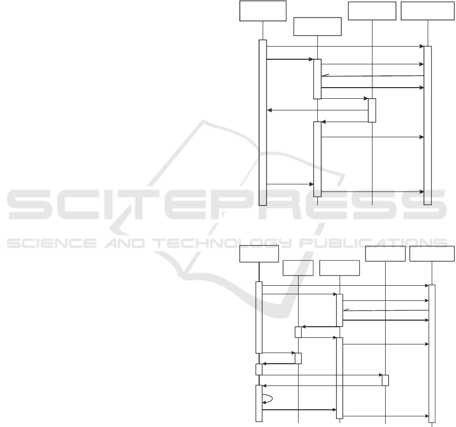
the logic of the real-time VS cycle (fig. 1). In the
setup mode, the order of VS operations is determined
by the operator (fig. 2). This mode is intended for
adjusting the adjustable parameters of the VS,
controlling the operability of the hardware devices
and viewing the results obtained during the automatic
mode session. Depending on the mode of operation,
the VS software performs the corresponding
configuration of flows representing the main
subsystems of the VS software.
Figure 1: The diagram of the VS software subsystems
interaction in the automatic mode.
Figure 2: The diagram of the VS software subsystems
interaction in the setup mode.
In order to simplify the transfer of the VS software
to other platforms, platform-dependent and platform-
independent components were identified in the VS
software framework. Platform-dependent
components include working with hardware devices
Subsystem for
processing images
Subsystem for the
visual data input
GUI Subsystem
Start
Client registration
“The VS automatic
mode” object
Turn on
Notification after the image capturing
Open the image buffer
Close the image buffer
Process image
Turn off
Client registration cancelling
View the current processing results
Subsystem for the
visual data input
Start
Client registration
Turn on
Notification after the image capturing
Open the image buffer
Copy image
Close the image buffer
Get the current
Image
Process image
View the current
processing results
Turn off
Client registration cancelling
Subsystem for
processing images
“The VS adjustment
mode” object
“Frame buffer”
object
GUI Subsystem
ICINCO 2019 - 16th International Conference on Informatics in Control, Automation and Robotics
348

and interaction with the operating system. Platform-
independent components include the processing of
visual data. The interface between platform-
dependent and platform-independent components is
based on the use of the class “Image”.
Analysis of the experience in developing
information support for mobile platforms allows us to
conclude that, after testing and debugging algorithmic
support, an increase in processing speed and a
reduction in power consumption is possible through
the use of specialized computers. For example, a
similar approach based on FPGA is used in stereo
vision systems for mars rovers (Matthies et al., 2007).
For the unification of equipment within a single
platform, Basler (Germany) proposes a combined
approach using graphics processors for training
neural networks and FPGA modules for computing
with trained networks on target platforms (Basler,
2016).
4 REPRESENTATION OF
OBJECTS-ALGORITHMS FOR
PROCESSING VISUAL DATA
IN THE FRAMEWORK OF VS
SOFTWARE
High-level algorithms for visual data processing in
the VS software perform processing focused on the
solution of a specific applied task. These algorithms
are used in two modes of the VS software operation –
in the automatic and setup mode. The processing of a
sequence of incoming digital images is performed
when operating in automatic mode. Therefore, the
class representing the high-level algorithm provides
storing of the results of processing a sequence of
images and some auxiliary data, for example, the
algorithm parameters that allow automatic or manual
setup.
In a high level algorithms of the software of the
considered VSs, one can distinguish a set of
sequentially executed stages of processing visual
data, the successful implementation of which leads to
the decision to detect images of objects of interest.
Such a processing algorithms structure can be
represented as a set of hypothesis generation
operations with subsequent verification. Feedback
may be possible between different processing steps,
for example, the result of a search for an object of
interest in the full image after successful detection
may reduce the search area on subsequent shots
taking into account the prediction of the object
movement.
High level algorithms, in which processing can be
represented as a set of operations, during which
elementary features of an image are combined into
features of a higher level taking into account a priori
information about objects of interest, can be
considered as algorithms with a “bottom-up
processing” structure.
If the VS performs detection and tracking of
objects of interest, a combination of high level
algorithms with the “bottom-up processing” and “top-
down processing” structure are used. During the
initial search without a forecast and a priori
information about the location of the object, an
algorithm “bottom-up processing” is used. First, the
elementary features of the entire image are
highlighted. Then they are grouped into clusters to
search for objects and an attempt to find the desired
objects among these clusters is made. When
processing subsequent images, the location of the
object of interest can be predicted, therefore, the VS
performs a transition to an algorithm with “top-down
processing”. In this case, a sequence of controls is
carried out at the intended location of the object,
confirming the presence of the object of interest and
the specification of its parameters.
When developing the framework of the VS
software when choosing how to program the high
level algorithms, the described features of the high
level processing algorithms were taken into account –
depending on the results of processing previous
images, different algorithms can be used; when
performing the high level algorithm, operations can
be performed on the generation and testing of
hypotheses that require program operations to be
significant in duration and representation in the
source text.
In the context of the structure of the framework of
the VS software, a set of common properties was
identified for high-level processing algorithms based
on the results of solving applied tasks. After
processing a portion of visual data (an image with a
time stamp), these algorithms generate some
numerical or symbolic description of the image – the
results of image processing. The algorithm can use
the results of processing previous images and contain
a set of parameters that can be controlled by the VS
operator and/or developer. Therefore, the following
functionality has been added to the class for
representing the high-level CAlgPrc processing
algorithm:
storage and access to an array of image processing
results;
initialization of the algorithm before processing
the sequence of images;
Technology of Developing the Software for Robots Vision Systems
349

processing of the next image of the sequence
provided with a time stamp;
storage and access to parameters affecting the
algorithm functioning.
Access to the listed possibilities is designed as
C++ virtual functions called from the VS software
framework.
In the applied VS developed on the basis of the
framework under consideration, a class is inherited
from the class CAlgPrc (fig. 3). This inherited class
performs processing as applied to the application
task. When using algorithms with “bottom-up” and
“top-down” processing, three classes inherited from
CAlgPrc are formed in the applied VS. Two of these
classes represent variants of the algorithm with
“bottom-up processing” and “top-down processing”,
and the third class aggregates them and dispatches
calls from the VS framework depending on the
current processing status.
Figure 3: A class diagram for the presentation of high-level
algorithms for the processing of visual data of the VS
software.
The “bottom-up”- style algorithm for the input
frames processing is applied at initial detection of an
object of interest and also at its loss during tracking.
A software object of this class
CVSAlgPrc_BottomTop is aggregated into the class
CVSAlgPrc. Its purpose is in processing of the
current captured frame (fig. 3). In this CVSAlgPrc
class a CVSAlgPrc_TopBottom object is also
aggregated. It implements the “top-down”- style
processing for tracking of an object of interest
according the prediction of its position. The
prediction of an object of interest movement and its
postion on the next frame is provided by the class
CPrediction. This class is a part of the class
CVSAlgPrc_TopBottom. Processing results are kept
by algorithms of both types as an array of
CAlgDataRecord objects. Such structure of
processing algorithms representation as a set of C++
classes provides simple usage of new image
processing algorithms in the unified software
framework.
5 INTEGRATION OF
REAL-TIME VS FRAMEWORK
WITH ROS SOFTWARE
In the robots software development the ROS
(designed for Linux OS) (Newman, 2017) is currently
widely used. This system is middleware which
provides a distributed computing system for
collecting and processing mixed data in robots
information systems. In the ROS model, the robot
software is supposed to be decomposed into parallel
tasks that are called “nodes” in the ROS terminology.
These nodes can operate on one or more computers
and run asynchronously and independently. Data
exchange between nodes is based on the transfer of
messages using the “one sender – many subscribers”
program pattern. ROS is used to develop various-
purpose robots, in particular, the successful
experience of building an autonomous car prototype
based on ROS (Fregin, 2017) is known. An
orientation of ROS to use in the Linux environment is
some kind of limitation. Microsoft has been porting
ROS into Windows (Ackerman, 2018) to expand the
scope of ROS.
The software framework considered in this article
can be integrated into the software of the ROS-based
information system of the robot in two ways:
1) Implementation of the ROS node in the Linux OS
environment. In this case, the node is
implemented in the Linux environment due to the
transfer of the framework subsystem that
performs real time image processing. his
subsystem is platform-independent in the VS
framework.
2) Implementing a ROS node in Windows OS
environment. In this implementation version, the
implementation assumes the use of the software
(Ackerman, 2018) and the use of the component
as part of the framework of the VS software that
implements the transfer of the VS data via ROS
messages. The advantage of this option is the
simplicity of implementation, its disadvantage is
the need to use a separate hardware node as part
of the information system of the robot.
These methods of implementing the ROS node for
processing visual data allow using the framework as
an extension of ROS which accelerates the
construction of software components for processing
visual data in the information systems of robots.
ICINCO 2019 - 16th International Conference on Informatics in Control, Automation and Robotics
350
6 EXAMPLES OF THE
APPLICATIONS BASED ON
THE VS FRAMEWORK
Let us give examples of the use of the above-
described hardware-software framework and VS
arrangement technology for application.
6.1 Determination of Aircraft Flight
Parameters based on Collecting
and Processing Visual Data
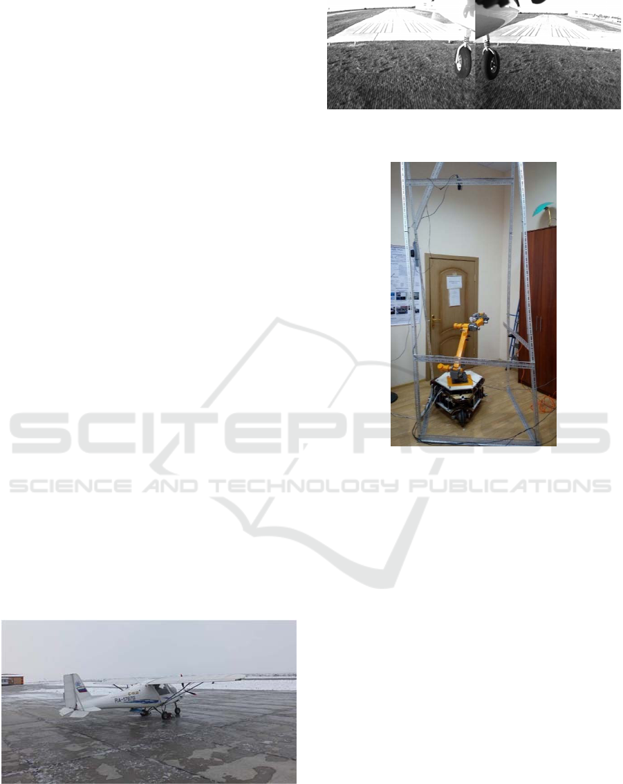
One of the considered tasks was the task of
developing the independent information channel for
determining the aircraft flight altitude, heel and pitch
based on visual data. This task was investigated and
the solution was verified by experiments at flying
laboratory (Fig. 4) with the computer vision system
installed on board. The computer vision system
consists of two video cameras that form a stereopair
directed forward and down at angle of approximately
75° to the vertical with a stereobase of approximately
1.3 m. The resolution of the cameras is 1600x1200
pixels, the frequency is 25 frames per second, the
focal length is approximately 1600 pixels (the span
angle is approximately 60°). The collecting and
processing visual data is performed by on-board
computer CompuLab IntensePC. Fig. 5 shows the
example of stereo image formed and processed by
onboard computer vision system.
On average, the measurements in the conducted
experiments were obtained with frequency of 10-
12 Hz. The accuracy of determining altitude on the
glide path was from 5% (at altitude of more than 50
m) to less than 1% (at altitude of less than 5 m). The
pitch and yaw angles were determined with accuracy
of 1.5-3 degrees.
Figure 4: Flying laboratory, where computer vision system
was tested to determine aircraft flight parameters based on
visual data.
Figure 5: Example of stereo image formed and processed
by onboard computer vision system.
Figure 6: General view of test bench for controlling
manipulator grip movements on movable base when
performing complex manipulations (opening the door).
6.2 Determining the Trajectory of
Manipulator Grip Movement
When Performing Complex
Movements
The described software architecture of the real-time
computer vision system was used in another practical
task – determining the trajectory of the manipulator
grip movement in the absolute coordinate system (in
the coordinate system associated with the object,
which is “external” in relation to the manipulator –
the door being opened) (Fig. 6, 7).
This system includes only two cameras connected
to one computing-controlling unit. The cameras are
located at distances within 1.5 m from the object of
interest. The observation conditions are stable. The
marker, marking the point on the grip, is a red LED.
The accuracy of determining the position of the
manipulator grip (beacon on the grip) was ±1.5 mm.
Technology of Developing the Software for Robots Vision Systems
351
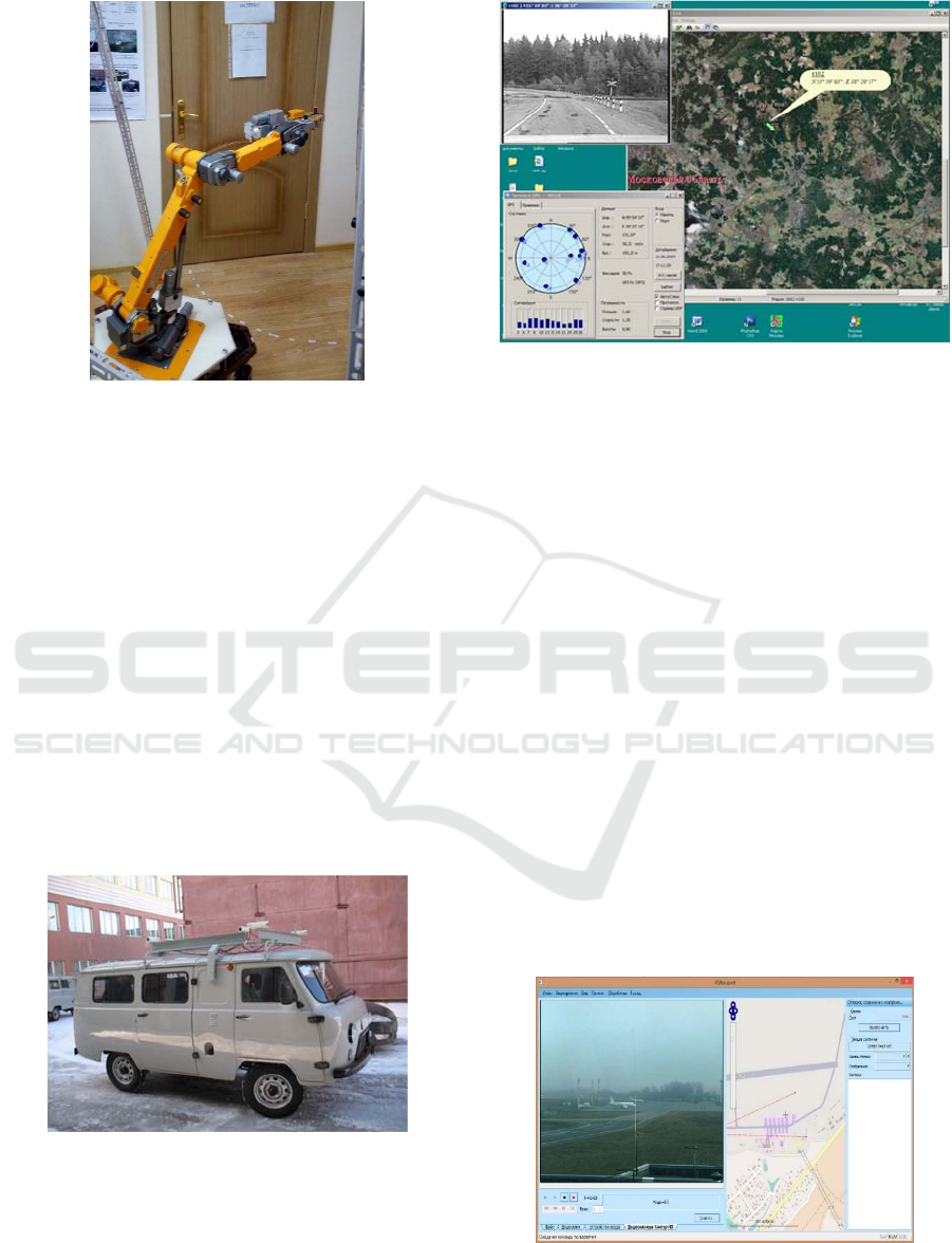
Figure 7: Manipulator grip marked with red LED marker.
6.3 Vision System for the Operative
Mapping Mobile Complex
Another task in which the described framework for
real-time VS software was used was the operational
mapping.
In this task two stereo modules fixed on the
mobile laboratory (fig. 8). This laboratory helped to
make binding and plotting of the objects of interest –
road signs, engineering constructions and other
objects at the directions of the technician (fig. 9).
The software and hardware architecture of the
real-time system in this task consists of three units for
computing and four video cameras. The purposes of
units is as follows: receiving and processing stereo
data (2 units of the same type) and geo-processing and
displaying data (1 unit).
Figure 8: Two stereosystems installed on the mobile
complex for operational mapping.
Figure 9: Mobile complex for operational mapping:
bindings of control objects (in coordinate system WGS-84).
6.4 Applied Vision Systems with
Multiples Fields of View
As already noted, the proposed architecture allows
the VS to be assembled from several, possibly far-
separated fields of view. As an example, we present
two systems for monitoring and recovering the
trajectory of objects movement in a known coordinate
system.
The first VS is designed for monitoring the
condition of parking areas and airport flight strip (fig.
10). A large number of 4-Mpix video cameras
installed on lighting masts and other elevations are
used to provide information support for the work of
airport ground service traffic controllers. The task of
VS is to provide traffic controllers with information
on airport areas of interest via the information
network, convert coordinates of airport plan/map and
GPS coordinates to the coordinates of vision fields and
vice versa, track the movements of objects (airplanes,
airfield vehicles) and provide images of areas of
interest indicated on the map with specified resolution.
Figure 10: Panel of airport ground service traffic controller
for work with computer vision system for ground
conditions monitoring.
ICINCO 2019 - 16th International Conference on Informatics in Control, Automation and Robotics
352
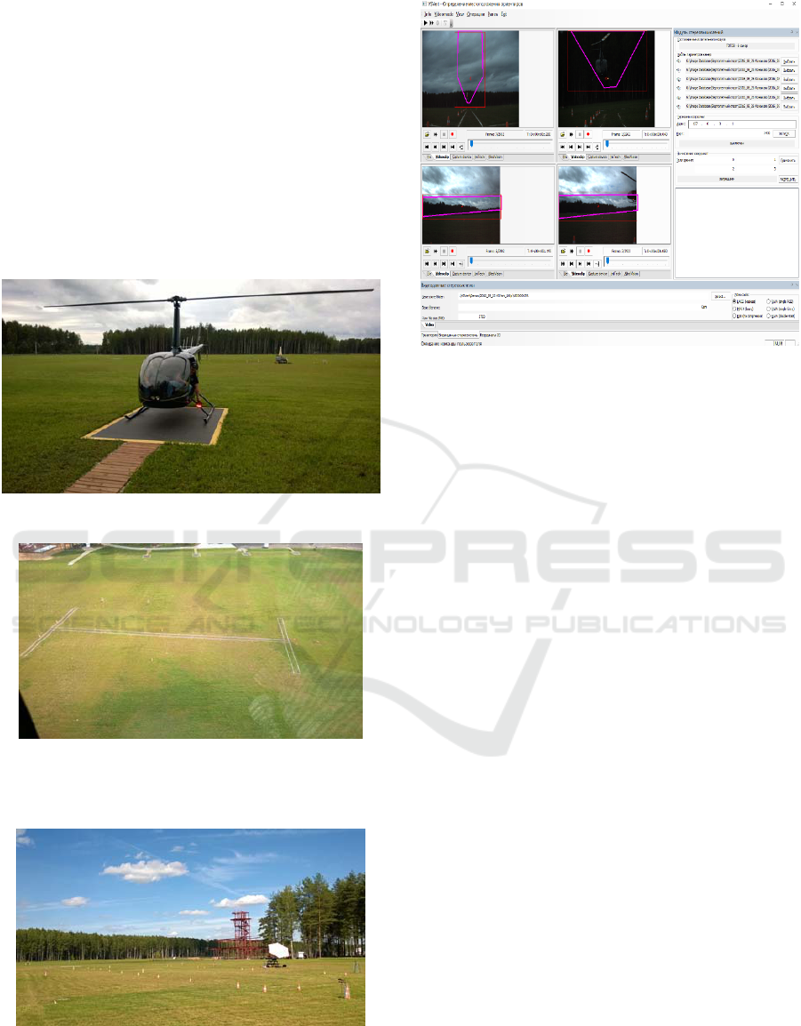
The task of second computer vision system is to
determine the accuracy of specified trajectory
following by objects of interest marked by light
beacons (fig. 11).
Six video cameras with overlapping fields of view
provide observation in a specified space volume – a
controlled spatial corridor (fig. 12). The VS consists
of two units, each of which processes data from three
fields of view. Before starting work, the system is
promptly calibrated using specially installed cones,
visible in each of the visual fields (fig.13). This VS
displays region of interest and the object of interest
track during real-time processing (fig. 14).
Figure 11: Beacon – marker of the object of interest.
Figure 12: General view of site for one of exercises
(rectilinear movement in specified spatial corridor) in
helicopter competition program.
Figure 13: Competitive site with installed markers for
calibration and binding of vision fields of computer vision
system.
Figure 14: Panel of vision system for a light beacon tracking
in multiply fields of view. On the images of fields of view
the projections of controlled space volume are shown.
As a processing result this VS determines in the
real-time mode an object of interest 3D trajectory
(with accuracy about ±2 cm).
7 CONCLUSIONS
The article describes the framework of the VS
software. It is a program that provides the main VS
actions on the input, processing and presentation of
visual data. The framework of the VS software
defines a set of abstract classes, common (for the
considered real time VS) software architecture,
common behavior, common data structures, and
common user interface. The framework of the VS
software is designed to simplify the solution of
similar tasks of processing visual data by reusing
software components and design solutions. The use
of the framework is aimed at simplifying the
modification and reducing the development time of
the VS software.
Two types of visual processing algorithms were
distinguished in the VS software: low-level and high-
level algorithms. Algorithms that are designed and
executed without taking into account a priori
information about the structure of the observed scenes
were assigned to low-level algorithms. High-level
algorithms are designed and used in relation to a
specific applied task solved with the help of VS. Low-
level algorithms are designed as functions or wrapper
classes. For the presentation of high-level algorithms
in the framework of the VS software, a base class has
been formed from which classes are inherited in the
Technology of Developing the Software for Robots Vision Systems
353

applied VS, which process visual data for the applied
task being solved.
The developed framework of the VS software has
been successfully applied to the implementation of
more than 15 real-time applied VS with one and
several fields of vision (Boguslavsky, 2003; Sokolov,
2013).
The presented framework can be used with the
ROS system as a prototype for the development of
ROS nodes that perform the real time processing of
visual data.
Implementation of the described framework on a
heterogeneous computing platform of onboard
execution is in the short term planned. This will
increase VS efficiency due to different algorithms
execution on specialized hardware.
ACKNOWLEDGEMENTS
This work is partially supported by a grant of the
RFBR no. 19-07-01113.
REFERENCES
Ackerman, E., 2018. Microsoft Announces Experimental
Release of ROS for Windows 10. In IEEE Spectrum, 1
October 2018. URL: https://spectrum.ieee.org/
automaton/robotics/robotics-software/microsoft-
announces-experimental-release-of-ros-for-windows-
10
Basler AG, 2016. Basler Development Kit for Embedded
Vision Applications. URL: https://www.baslerweb.
com/en/news-press/news/new-basler-development-kit-
for-embedded-vision-applications/12238/
Boguslavsky, A.A., Sokolov, S.M., 2003. Component
Approach to the Applied Visual System Software
Development. In 7th World Multiconference on
Systemics, Cybernetics and Informatics (SCI2003),
July 27-30, Orlando, Florida, USA, 2003.
DBS GmbH., 1998. AdOculos 4.0, DBS GmbH, Bremen,
Germany, http:\\www.dbs-imaging.com.
Eckstein, W., Steger, C., 1999. The Halcon Vision System:
An Example for Flexible Software Architecture. In
Proc. of the 3rd Japanese Conference on Practical
Applications of Real-Time Image Processing, p. 18-23.
Fayad, M.E., Johnson, R.E., Schmidt, D.C., 1999. Building
Application Frameworks: Object-Oriented
Foundations of Framework Design. – USA, New York:
John Wiley and Sons, 688 pg.
Fregin, A. et al., 2017. Building a Computer Vision
Research Vehicle with ROS. In Proc. of the ROSCon
2017, 21 September 2017, Vancouver, Canada. URL:
https://roscon.ros.org/2017/presentations/ROSCon%2
02017%20Computer%20Vision%20Research%20Veh
icle.pdf
Gorbunov-Posadov, M.M., 1999. Extendable software.
Moscow, Poliptih, 336 pg.
Intel Corp., 2017. Intel Integrated Performance Primitives
2017 Update 2. Developer Reference. Vol. 2: Image
Processing. Intel Corp., USA, 1032 pg.
Kaehler, G., Bradski, G., 2017. Learning OpenCV 3:
Computer Vision in C++ with the OpenCV Library.
O’Reilly Media Inc., 990 pg.
Klinger, T., 2003. Image Processing with LabVIEW and
IMAQ Vision. Prentice Hall, 319 pg.
LEAD Technologies Inc., 2017. LEADTOOLS Imaging
SDK. Version 19. https://www.leadtools.com/
Matrox Electronic Systems Ltd., 2016. Matrox Imaging
Library 10. http://www.matrox.com/imaging/
Matrox Electronic Systems Ltd., 2017. Matrox Design
Assistant. http://www.matrox.com/imaging/en/
products/software/design-assistant-machine-vision-
software/
Matthies, L. et al., 2007. Computer Vision on Mars. In Int.
Journal of Computer Vision, October 2007, No. 75 (1),
pp. 67-92.
MVTec Software GmbH, 2017. HALCON Machine Vision
Library. http://www.mvtec.com/products/halcon/
Newman, W., 2017. A Systematic Approach to Learning
Robot Programming with ROS. Chapman and
Hall/CRC, 530 pg.
Olson, T.J., Klop, N.G., Hyett, M.R., Carnell, S.M., 1992.
MAVIS: A Visual Environment for Active Computer
Vision. In Proc. IEEE Workshop on Visual Languages,
Washington, USA, Sept. 15-18, 1992, p.170-176.
Pisoft Image Framework 8.0, 2000. Information
Technology Institute, http:\\www.iitvision.
ru\pisoft.htm.
Sokolov, S. M., Boguslavsky, A. A., Vasilyev, A. I.,
Trifonov, O.V., 2013. Development of software and
hardware of entry-level vision systems for navigation
tasks and measuring. In Advances in Intelligent Systems
and Computing (Springer), 2013, vol. 208, pp. 463-476.
Touchton, R.A., Crane, III C.D., 2009. Software
Architectures for Autonomy. In: Meyers R. (eds)
Encyclopedia of Complexity and Systems Science.
Springer, New York, NY.
ICINCO 2019 - 16th International Conference on Informatics in Control, Automation and Robotics
354
