
RE4DIST: Model-based Elicitation of Functional Requirements for
Distributed Systems
Roman Wirtz and Maritta Heisel
Working Group Software Engineering, University of Duisburg-Essen, Duisburg, Germany
Keywords:
Requirements Engineering, Distributed Systems, Model-based, Functinonal Requirements, Requirements
Elicitation.
Abstract:
Nowadays, software-based systems are often decomposed into several distributed subsystems. The complexity
of those systems and the decomposition in different subsystems requires a detailed analysis and documentation
of functional requirements. Documenting and managing the functional requirements in a consistent manner is
a challenge for software engineers. The requirements for each subsystem cannot be considered in isolation,
but it is necessary to state the relations between the functional requirements, too. In this paper, we propose a
model-based method to elicit and document functional requirements for distributed systems. Our contribution
is two-fold: By providing a requirements model, we first enable consistent documentation of the requirements
for the different subsystems and make relations between them explicit. Second, we propose a method to sys-
tematically elicit functional requirements of distributed systems. By using the proposed model, we document
the results in a consistent manner. Our approach is tool supported, which simplifies its application.
1 INTRODUCTION
Nowadays, software-based systems are often realized
as distributed systems. (Tanenbaum and Steen, 2006)
define a distributed system as a system whose com-
ponents are located on different connected comput-
ers. Those components communicate via messages
to achieve a common goal. Using functional require-
ments, we describe the functionalities of a distributed
system during requirements engineering that are nec-
essary in order to achieve that common goal.
The complexity of distributed systems faces soft-
ware engineers with new problems during the whole
software development process. Especially in one of
the earliest phases of software development, namely
requirements engineering, it is a challenge for engi-
neers to capture all aspects of a distributed system un-
der development. Although the different components
may be deployed independently of each other in dif-
ferent environments, the functionalities of the compo-
nents highly depend on each other. Thus, it does not
suffice to elicit and document requirements for each
component independently. In addition, the connection
between the components is often remote and hence, is
not reliable.
For further analysis, e.g. with regard to privacy or
security, it is of essential importance to document the
dependencies and interfaces between the subsystems
in a consistent and systematic manner. For example,
an attacker may inject malicious code on the client
side which will then affect stored data on the server
side. In addition, the components of distributed sys-
tems are often connected via unreliable connections,
e.g. via the Internet.
Our aim is to assist software engineers in per-
forming detailed and systematic elicitation and doc-
umentation of functional requirements for distributed
systems. In this paper, we propose a model-based
method called RE4DIST (Requirements Engineering
for DISTributed Systems) which is based on Michael
Jackson’s problem frames (Jackson, 2001) which al-
lows to model functional requirements in a system-
atic manner. We first introduce a requirements model
based on his terminology, which we extend with re-
gard to distributed systems to make the relations be-
tween the different subsystems and their cross-cutting
requirements explicit. Based on that model, we
provide a method to systematically elicit and docu-
ment functional requirements and their relations. Our
method starts with understanding and documenting
the context in which the distributed system shall op-
erate along with the initial set of functional require-
ments. Next, we identify overlapping functional re-
quirements. We go on with decomposing the over-
Wirtz, R. and Heisel, M.
RE4DIST: Model-based Elicitation of Functional Requirements for Distributed Systems.
DOI: 10.5220/0007919200710081
In Proceedings of the 14th International Conference on Software Technologies (ICSOFT 2019), pages 71-81
ISBN: 978-989-758-379-7
Copyright
c
2019 by SCITEPRESS – Science and Technology Publications, Lda. All rights reserved
71
all context into overlapping parts, each describing the
concrete context for a subsystem. Last, we use prob-
lem diagrams to make dependencies between require-
ments explicit. For each step of the method, we define
validation conditions that ensure detecting errors dur-
ing the application of the method as early as possible.
Using diagrams, we provide a user-friendly view on
the elements of the model.
To simplify the application of our method, we pro-
vide a tool
1
based on the Eclipse Modeling Frame-
work (Steinberg et al., 2009). The tool assists
software engineers in instantiating the model using
graphical editors and wizards that guide through the
method’s application. Using the semantics of the
models along with OCL (Object Constraint Lan-
guage), we formalize the validation conditions for au-
tomatic evaluation. For the diagrams we use in our
method, we provide an intuitive notation based on
Google’s Material Design
2
. In the present paper, we
describe the tool for each step of the method in detail.
The remainder of the paper is the following: In
Section 2, we introduce Michael Jackson’s problem
frames as background knowledge. We introduce our
requirements model for distributed systems in Sec-
tion 3, and we describe our proposed method in Sec-
tion 4. Using a small case study, we exemplify the
application of the method in Section 5. We discuss
related work in Section 6 and conclude the paper in
Section 7 with a brief summary and an outlook on fu-
ture research directions.
2 BACKGROUND
To model functional requirements, we make use of the
problem frames approach as introduced by Michael
Jackson (Jackson, 2001). We consider two types of
diagrams, context diagrams and problem diagrams,
which both consist of domains, phenomena and in-
terfaces.
Machine domains (
) represent the piece of soft-
ware to be developed.
Problem domains represent entities of the real
world. There are different types: biddable domains
with an unpredictable behavior, e.g. persons ( ),
causal domains ( ) with a predictable behavior, e.g.
technical equipment, and lexical domains ( ) for data
representation. A domain can take the role of a con-
nection domain ( ), connecting two other domains,
e.g. user interfaces.
1
RE4DIST - https://swe.uni-due.de (last access: May
16, 2019)
2
Google Material - https://material.io (last access:
March 15, 2019)
Person
Software
Information
Equipment
P!{provideInformation}
S!{showInformation}
S!{requestInformation}
I!{information}
S!{controlEquipment}
Figure 1: Example for Context Diagram.
Interfaces between domains consists of phenom-
ena. There are symbolic phenomena, representing
some kind of information or a state, and causal phe-
nomena, representing events, actions and so on. Each
phenomenon is controlled by exactly one domain and
can be observed by other domains. A phenomenon
controlled by one domain and observed by another is
called a shared phenomenon between these two do-
mains. Interfaces (solid lines) contain sets of shared
phenomena. Such a set contains phenomena con-
trolled by one domain indicated by X!{...}, where X
stands for an abbreviation of the controlling domain).
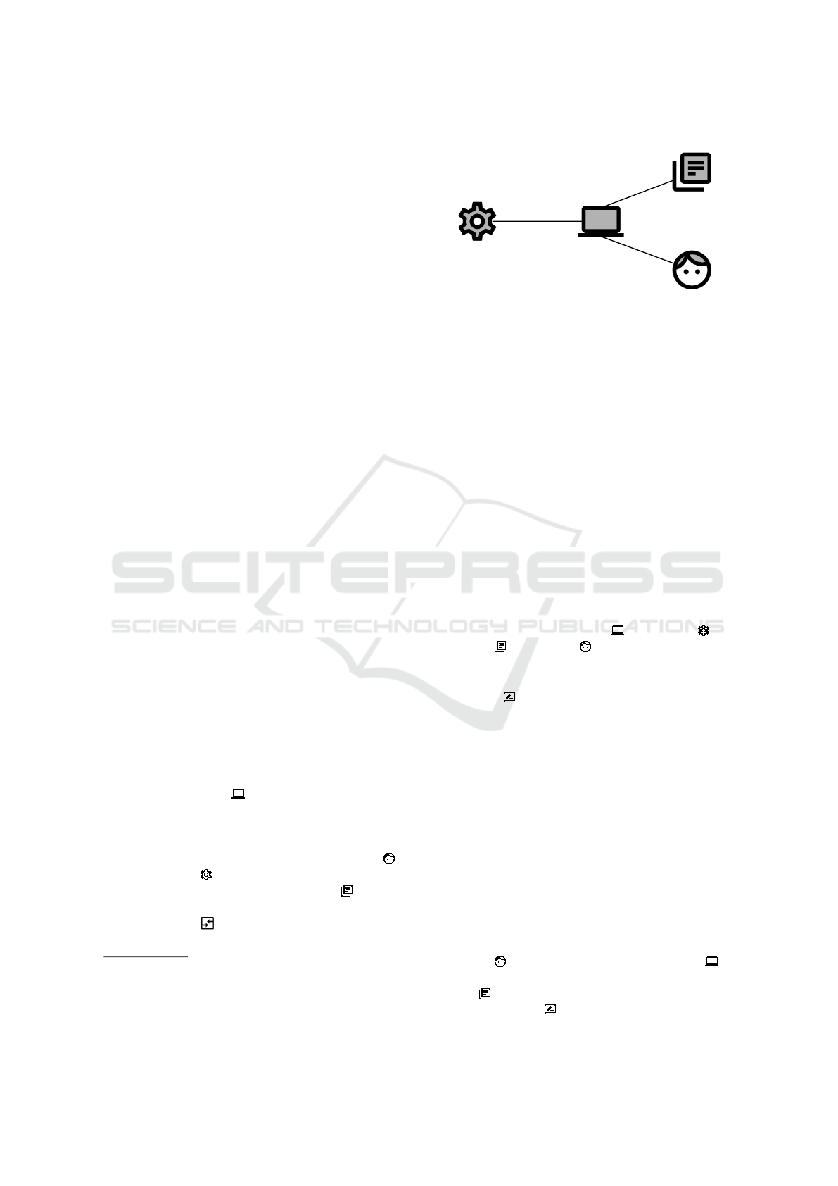
A context diagram describes where the problem,
i.e. software to be developed, is located and which
domains it concerns. It does not contain any require-
ment. We show an example of such a diagram in Fig-
ure 1. It contains four domains and the corresponding
interfaces. There are Software , Equipment , In-
formation , and Person .
A problem diagram is a projection of the context.
It contains a functional requirement (represented by
the symbol ) describing a specific functionality to
be developed. A requirement is an optative statement
which describes how the environment should behave
when the software is installed.
Some phenomena are referred to by a requirement
(dashed line to controlling domain), and at least one
phenomenon is constrained by a requirement (dashed
line with arrowhead and italics). The domains and
their phenomena that are referred to by a requirement
are not influenced by the machine, whereas we build
the machine to influence the constrained domain’s
phenomena in such a way that the requirement is ful-
filled.
In Figure 2, we show a small example describing a
functional requirement for updating some information
which is a projection of the context given in Figure 1.
A Person provides information to Software to
be updated. We make use of a lexical domain Infor-
mation to illustrate a database. The functional re-
quirement Update refers to the phenomenon up-
ICSOFT 2019 - 14th International Conference on Software Technologies
72

Update
Person
Software
Information
updateInformation
information
P!{provideInformation}
S!{updateInformation}
Figure 2: Example for Problem Diagram.
dateInformation and constrains the phenomenon in-
formation.
The icons we use in our diagrams differ from Jack-
son’s notation. We adopted icons from Google’s Ma-
terial Design
3
to provide intuitive views for the dia-
grams.
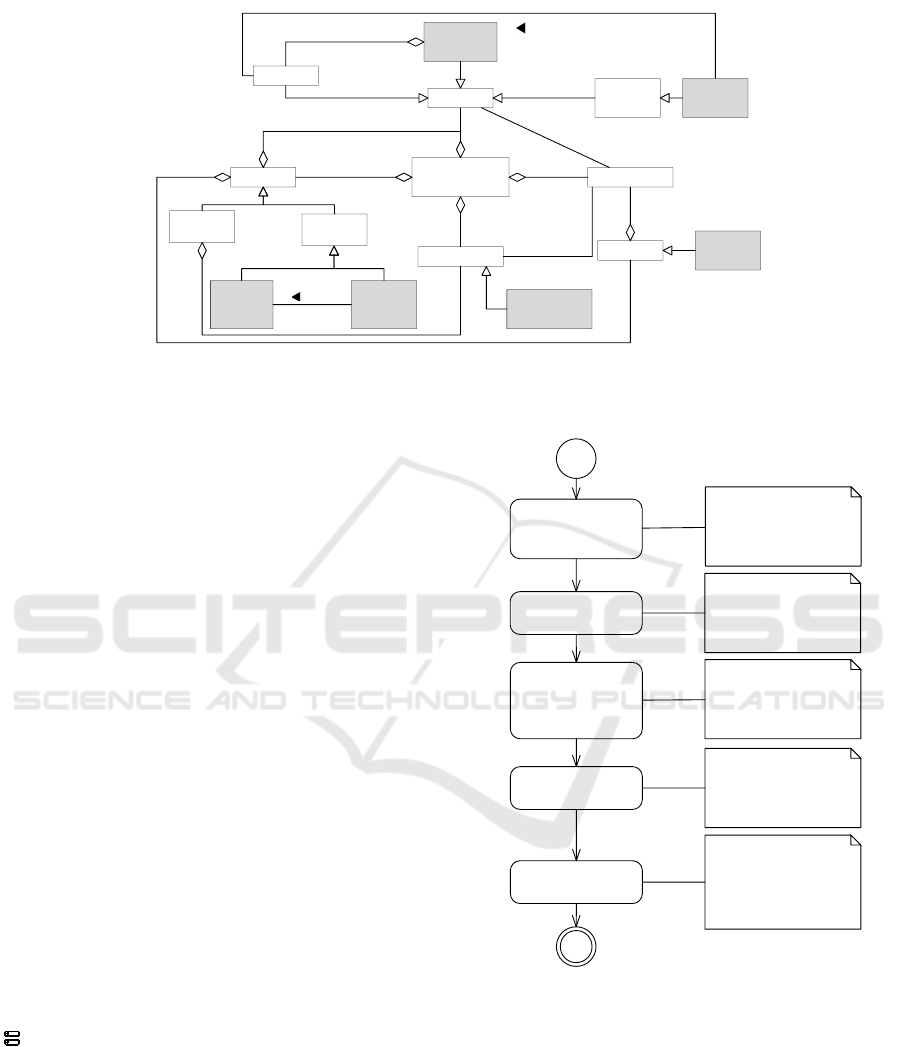
3 REQUIREMENTS MODEL
In the following, we propose a requirements model
to document the requirements for a distributed sys-
tem. In Figure 3, we illustrate the structure and the
core elements of that model. We use the problem
frames notation as introduced in Section 2 as the ba-
sis for it, and we introduce additional elements to de-
scribe functional requirements of distributed systems.
We highlight newly introduced elements in gray. The
root element of the model is the Requirements Model
itself. It contains two types of Diagrams: Problem
Diagrams and Context Diagrams. We introduce two
new types of context diagrams. A Global Context Di-
agram describes the overall context of the distributed
system. A Sub Context Diagram is derived from it
and describes the context for a specific subsystem.
The model contains a set of Domains, which are
contained in at least one diagram. We distinguish four
types of domains: (1) Machine, (2) Problem Domain,
(3) Remote Machine, and (4) Distributed System. A
distributed system consists of at least two machine
domains, each representing a subsystem. A remote
machine is a problem domain and denotes a machine
that is part of the distributed system. Later on, we
use the newly introduced problem domain to make
the relation between different subsystems explicit. A
machine domain represents the part of the distributed
system to be developed, and a remote machine rep-
resents other subsystems that are related to it. Each
3
Google Material - https://material.io (last access:
March 15, 2019)
domain can control an arbitrary number of Phenom-
ena.
An Interface contains a set of phenomena, and
each diagram contains at least one interface between
two domains. We introduce a specialization of an in-
terface called Remote Interface. Such an interface
connects a machine with a remote machine and makes
an unreliable connection explicit. To describe the re-
alization of interfaces in more detail, we adapt the so
called attack vector from the Common Vulnerability
Scoring System (CVSS) (FIRST.org, 2015). An at-
tack vector has predefined values to describe how an
attacker accesses a vulnerable component. We intro-
duce an AccessVector to describe how domains in-
teract with each other. The vector distinguishes the
following four values: Network (N) describes remote
connections through different networks, e.g. connec-
tions via the internet, adjacent (A) stands for local
network connections, local (L) means access to do-
mains not connected to the internet, and physical (P)
describes physical access to domains.
Requirements are part of a problem diagram and
describe the functionalities of the distributed system.
We introduce Distributed Requirements to describe
functional requirements which concern different sub-
systems.
Tool Support. We decided to build our tool based
on the Eclipse Modeling Framework (EMF) (Stein-
berg et al., 2009). EMF is open source and offers a
wide range of products for model-based development.
For example, we will use Eclipse Sirius
4
to provide a
graphical editor for the application of our method.
For our requirements model, we define an Ecore
meta-model for the requirements model. The meta-
model provides semantic rules, that ensure a consis-
tent and correct instantiation. The notation is similar
to UML class diagrams (Object Management Group,
2015) and consists of classes, their attributes, and re-
lations between them. Additionally, we make use of
OCL expressions (Object Management Group, 2014)
to define further semantic rules and to define formal
validation conditions that help to validate instances of
the meta-model. In the following, we make use of the
model to document the results of our method when
using our tool. Due to its complexity, we do not show
the Ecore meta-model here.
4
Eclipse Sirius - https://www.eclipse.org/sirius/ (last ac-
cess: March 12, 2019)
RE4DIST: Model-based Elicitation of Functional Requirements for Distributed Systems
73
Requirements
Model
Problem
Diagram
Context
Diagram
Problem
Domain
Machine
Distributed
System
Remote
Machine
Domain
Diagram Phenomenon
controls
Interface
Requirement
Remote
Interface
refers to
constrains
reference to
Distributed
Requirement
1
1..*
2..*
1
1
1
1
*
1..*
1
1..*
1
1..*
1..*
1..* *
1..*
1..*
Global
Context
Diagram
Sub
Context
Diagram
derived
from
Figure 3: Core Elements of Requirements Model.
4 METHOD
Our method to elicit and document functional require-
ments for distributed systems (DS) consists of five
steps. In Figure 4, we provide an overview of the
steps and the corresponding input and output of each
step. For each step, we present examples of validation
conditions (VC) to ensure that errors occurring dur-
ing the application of our method can be identified as
early as possible. In addition, we briefly describe the
tool which supports the application of our method. In
Section 5, we provide a case study which exemplifies
our method.
4.1 Step 1: Define Global Context &
Subsystems
The goal of the first step is to get an understanding of
the global context in which the distributed system will
operate. We consider an informal scenario description
as input. Based on this input, we identify problem
domains in the context of the distributed system.
We document the results in a context diagram as
described in Section 2. There is exactly one dis-
tributed system domain (represented by the symbol
) in the context diagram which covers all subsys-
tems that shall be developed. Since existing sys-
tems do not need to be developed, we describe them
by means of causal domains. Using interfaces, we
describe the communication between the distributed
system and the environmental domains.
For the distributed system, we identify those sub-
systems that shall be developed. There are at least
two subsystems. The subsystems do not necessarily
differ from each other. For example, in a peer-to-peer
1. Define Global
Context &
Subsystems
2. Elicit Func�onal
Requirements for DS
3. Iden�fy
Distributed
Func�onal
Requirements
4. Decompose
Context
5. Create Problem
Diagrams
Input: Informal scenario
descrip�on
Output: Global context
diagram
Input: Informal scenario
descrip�on
Output: List of func�onal
requirements
Input: List of func�onal
requirements
Output: Annotated list of
func�onal requirements
Input: Context diagram,
Func�onal Requirements
Output: Sub context
diagrams
Input: Sub context
diagrams; Func�onal
requirements
Output: Set of problem
diagrams
Figure 4: Method Overview.
system, the subsystems realized as peers can have the
same functional requirements. We represent the sub-
systems as machine domains with aggregations to the
distributed system in the context diagram.
Validation Conditions. Based on the above-
presented description of the step, we define four
validation conditions (VC).
VC1 There is exactly one distributed system in the
global context diagram.
ICSOFT 2019 - 14th International Conference on Software Technologies
74

VC2 A distributed system consists of at least two
subsystems.
VC3 All subsystems have been identified and have
been documented in the context diagram.
VC4 All problem domains of the context have been
identified, e.g. stakeholders and technical equip-
ment.
Tool Support. As mentioned in Section 3, we make
use of an Ecore model for our tool. To define the
initial context and subsystems, we provide a graph-
ical editor based on Eclipse Sirius
5
. The editor assists
software engineers in creating the initial context dia-
gram and ensures the semantic rules provided by the
model.
Our tool supports the automatic validation of VC1
and VC2. The other two conditions have to be val-
idated manually, but we ask the user of the tool to
confirm the validation before proceeding to the next
step.
4.2 Step 2: Elicit Functional
Requirements for DS
Based on the informal scenario description and the
global context diagram, we identify the functional re-
quirements that the distributed system shall satisfy.
For each functional requirement, we define a unique
name and a proper description of the expected func-
tionality, and we document both textually.
Validation Conditions. For the second step of our
method, we define two validation conditions.
VC5 Each functional requirement has a unique name
and a valid description.
VC6 Each functional requirement has been identified
and has been documented.
Tool Support. Our tool provides a table to list all
functional requirements one by one. To this table, one
can add new requirements using a wizard, and all re-
quirements will be stored in the model to be reusable
in further steps.
The first validation condition can partially be
checked via the model, whereas the second one has
to be confirmed by the user of our tool before pro-
ceeding to the next step.
5
Eclipse Sirius - https://www.eclipse.org/sirius/ (last ac-
cess: March 12, 2019)
4.3 Step 3: Identify Distributed
Functional Requirements
Due to different environments in which the subsys-
tems may be realized, e.g. a mobile application in
contrast to a server application, different teams will be
involved in developing a distributed system. There-
fore, we distinguish requirements that only concerns
a single subsystem, and others requiring the interac-
tion between different subsystems to be satisfied.
In the present step, we make the distinction of
types explicit to assign the requirements to the re-
sponsible development team. In addition, we docu-
ment dependencies of subsystems for satisfying re-
quirements. For each requirement, we decide about
its type and assign a set of responsible subsystems. A
requirement that concerns at least two subsystems has
to be considered as distributed, and in a distributed
system there is at least one requirement concerning
several subsystems.
Validation Conditions. We define two validation
conditions for the third step of our method.
VC7 Only requirements concerning at least two sub-
systems have been classified as distributed.
VC8 At least one requirement has been defined as
distributed.
Tool Support. To specify the type of requirement,
our tool presents the list of requirements to the user
where he/she can select the type. For distributed re-
quirements, we provide a dialog to select the related
subsystems. Using references to the corresponding
machine domains, our tool documents the results in
the model and updates the list of requirements.
Both stated validation conditions can be validated
automatically using our tool.
4.4 Step 4: Decompose Context
In the first step of our method, we described the global
context of the distributed system. As mentioned ear-
lier, different teams will be involved in developing
a distributed system. In the present step, we break
down the global context in smaller units, one for each
subsystem. Again, we make use of context diagrams
which we call Sub Context Diagram to document the
results, one for each subsystem.
Such a sub context diagram consists of the ma-
chine domain for the subsystem and the relevant prob-
lem domains. To express the relation between the
subsystems, we introduce new elements to the con-
text diagram, namely remote machines (represented
RE4DIST: Model-based Elicitation of Functional Requirements for Distributed Systems
75

by the symbol ) and remote interfaces (dotted line).
For each related subsystem with which communica-
tion exists, we add a remote machine domain and the
corresponding remote interface.
The interfaces between machine and problem do-
mains are taken from the global context definition,
but the remote interfaces describing the communica-
tion between subsystems do not exist there and hence,
need to be added.
The set of sub context diagrams help developers
in focusing on the context of a concrete subsystem.
However, we do not omit the relation to other subsys-
tems.
Validation Conditions. To validate the application
of the fourth step, we define the following five condi-
tions:
VC9 There is one context diagram for each subsys-
tem.
VC10 Each domain of the initial context diagram is
contained in at least one context diagram of a sub-
system.
VC11 Interfaces between machine and remote ma-
chine have been marked as remote.
VC12 Each context diagram contains all related sub-
systems represented by means of remote machine
domains.
VC13 Only problem domains directly connected to
the subsystem or via a connection domain are part
of the context diagram.
Tool Support. Our tool automatically creates a sub
context diagram for each subsystem. It automatically
adds related machines based on the requirement spec-
ifications taken from step three and the remote inter-
faces in-between. We also provide a wizard to select
relevant problem domains, phenomena, and interfaces
from the initial context. A graphical editor allows ad-
justing the generated diagrams. To ensure consistency
between all steps, we make use of model references to
the results of the previous steps.
Except for the last one, our tool allows to automat-
ically evaluate the validation conditions. For the last
step, it asks the user to confirm the manual validation.
4.5 Step 5: Create Problem Diagrams
The final step of our method is the creation of problem
diagrams for the functional requirements we identi-
fied in the second step. For requirements not being
classified as distributed, we create problem diagrams
as proposed by Michal Jackson (Jackson, 2001) based
on the sub context diagram for the responsible sub-
system. To specify an interface in more detail, it is
possible to add connection domains, e.g. a user inter-
face.
To specify the interfaces in more detail, we anno-
tate the type of connection described with an access
vector as introduced in Section 3.
For requirements being classified as distributed,
we create one problem diagram per involved subsys-
tem. Those diagrams contain the relevant problem do-
mains taken from the sub context diagram and remote
machines for subsystems related to the functional re-
quirement. To connect machine and remote machines,
we again make use of remote interfaces.
A distributed requirement is characterized by the
communication between machine and remote ma-
chine for its satisfaction. Therefore, the requirement
refers to or constrains at least one phenomenon of
a remote machine. Refers to means that the remote
machine triggers an event of the machine to be con-
sidered, and constrains means that the machine to be
considered triggers an event of the remote machine.
The annotated phenomenon describes that event.
Validation Conditions. For the final step of our
method, we define three validation conditions.
VC14 Each functional requirement is contained in at
least one problem diagram.
VC15 For each distributed requirement, there is one
problem diagram for each involved subsystem.
VC16 A distributed requirement refers to or con-
strains at least one phenomenon of a remote ma-
chine.
Tool Support. Using our tool, users can generate
problem diagrams for each requirement and each sub-
system, respectively. The initial structure of the dia-
grams can be generated automatically. In addition, we
provide a wizard that assists users of the tool in select-
ing relevant problem domains and interfaces from the
model, and in adding connection domains. Again, we
use references to existing model elements to ensure
consistency between all diagrams.
Our tool can evaluate all validation conditions au-
tomatically.
4.6 Final Output
The final output of our method is a set of diagrams
for each subsystem. The set consists of a context dia-
gram for the subsystem and problem diagrams which
describe the functional requirements to be satisfied
ICSOFT 2019 - 14th International Conference on Software Technologies
76
by the subsystem. The set allows independent de-
velopment of each system while still preserving de-
pendencies to other subsystems. Since the output is
model-based, changes will be propagated throughout
the whole model.
5 CASE STUDY
In the following, we apply our method to a smart
grid case study, which is inspired by the OPEN Meter
project (OPEN meter Consortium, 2009). The dia-
grams and tables we show in the following have been
created with our tool.
5.1 Informal Scenario Description
For the present paper, we focus on a small part of the
overall scenario that concerns the customer’s home.
We provide the initial scenario description in the fol-
lowing: The communication hub is the central gate-
way, for which software shall be developed. Smart
meters measure the customer’s power consumption.
They transmit the data in given intervals to the com-
munication hub where the data is stored. In addi-
tion, a customer can connect to the communication
hub using a mobile application on a smartphone or
tablet. Customers can configure the mobile applica-
tion to connect to their communication hub and can
then request a list of stored meter data.
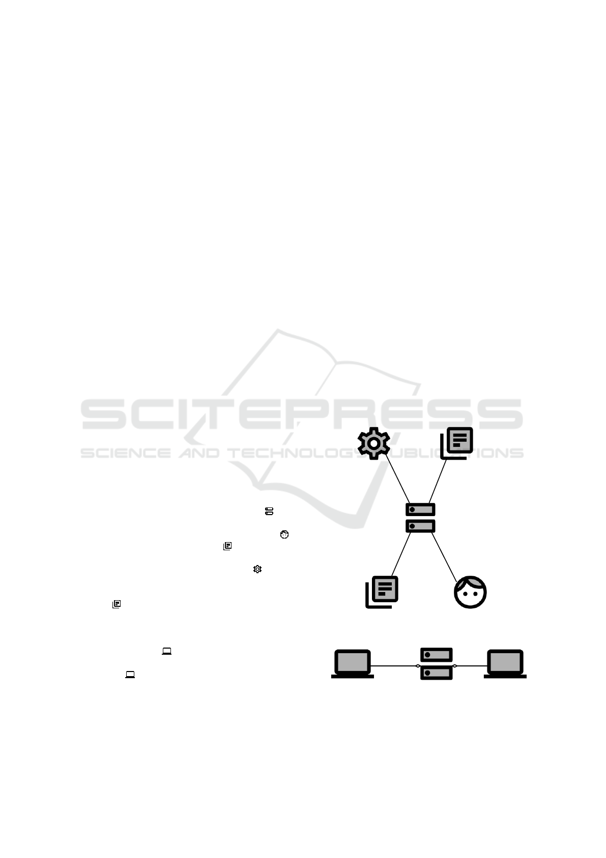
5.2 Step 1: Define Global Context &
Subsystems
Our distributed system is called Open Meter , for
which we present the global context diagram in Fig-
ure 5a. We identified the stakeholder Customer ,
who is able to enter a Configuration for the mobile
application and who can request previously stored
meter data. We consider a Smart Meter as ex-
isting technical equipment. Measured data will be
stored persistently in the database which we call Me-
ter Data .
In Figure 5b, we provide an overview of the
different subsystems that shall be developed. Our
distributed system consists of two subsystems: The
Communication Hub will be realized as an embed-
ded system for the gateway at customers’ home. The
Mobile App will be realized as software for smart-
phones and tablets.
5.3 Step 2: Elicit Functional
Requirements for DS
For our scenario, we identify three functional require-
ments which we document in a table such as shown in
Table 1.
Enter Configuration. Customers can configure the
mobile application to connect to the communica-
tion hub.
Request Meter Data. Customers can request a list
of their meter data via the mobile application.
Store Meter Data. In given intervals, smart meters
send the measured data to the communication
hub, where it is stored persistently.
5.4 Step 3: Identify Distributed
Functional Requirements
Next, we identify those requirements that concern
more than one subsystem.
Enter Configuration. Customers enter the configu-
ration locally in the mobile application. There is
no communication with other systems and there-
fore, the requirement is not considered as dis-
tributed.
Open Meter
Customer
Smart Meter
Meter Data
Configuration
C!{enterConfiguration,
requestMeterData}
OM!{provideMeterData}
SM!{sendMeterData}
Conf!{configuration}
OM!{storeConfiguration}
MD!{meterData}
OM!{storeMeterData}
(a) Context Diagram
Open Meter
Communication Hub
Mobile App
(b) Subsystems
Figure 5: Case Study - Global Context Diagram & Subsys-
tems.
RE4DIST: Model-based Elicitation of Functional Requirements for Distributed Systems
77
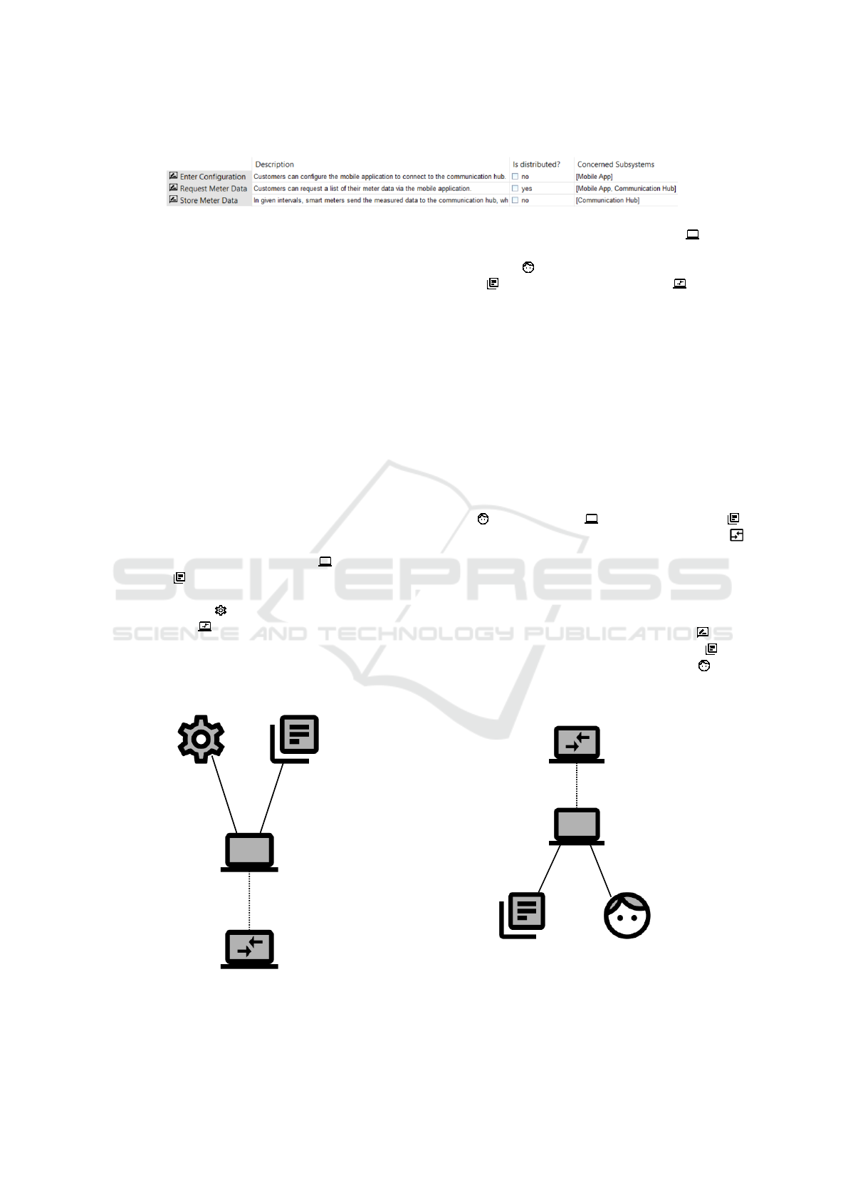
Table 1: Case Study - Requirements.
Request Meter Data. To request the meter data, cus-
tomers use their mobile application to access the
communication hub. The communication hub
then returns the stored data. Both subsystems are
involved in that process, and therefore we con-
sider the requirement as distributed.
Store Meter Data. Smart meters connect to a com-
munication hub. There is no interaction with other
subsystems.
We marked the distributed requirement in the table
as shown in Table 1.
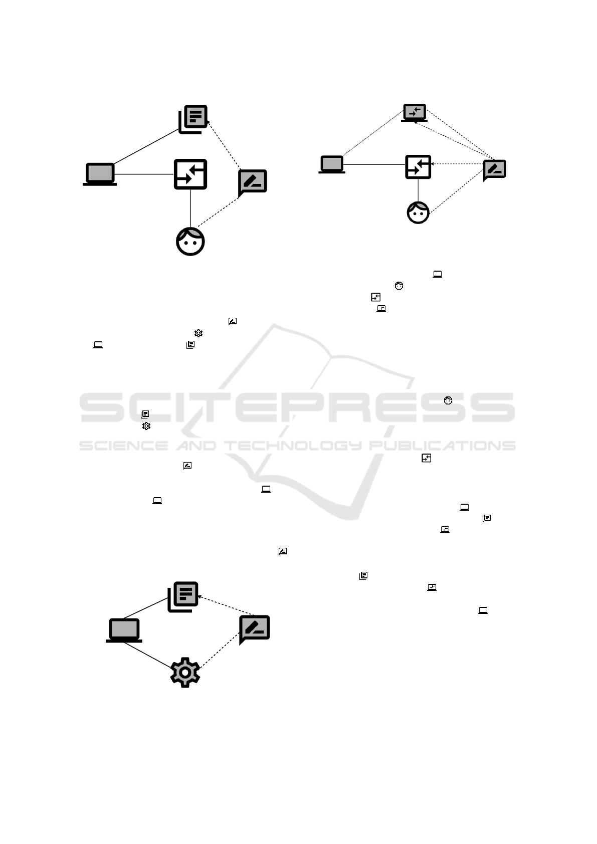
5.5 Step 4: Decompose Context
Our scenario contains two subsystems, Communica-
tion Hub and Mobile Application. Hence, it is neces-
sary to define one sub context diagram for each.
Communication Hub. Figure 6 shows the context
diagram for the Communication Hub . The domain
Meter Data represents the database where the com-
munication hub stores the measured data persistently,
and a Smart Meter sends the measured data. Since
the Mobile App is also part of the distributed sys-
tem, it is represented as a remote machine. The inter-
face between both subsystems is unreliable and there-
fore marked as a remote interface.
Communication Hub
Meter Data
Smart Meter
Mobile App
CH!{storeMeterDataCH}
MD!{meterData}
CH!{provideMeterDataCH}
MA!{requestMeterDataMA}
SM!{sendMeterData}
Figure 6: Case Study - Sub Context Diagram for Communi-
cation Hub.
Mobile Application. For the Mobile App , we de-
velop the context diagram in Figure 7. It consists of
the Customer who uses the application, a Config-
uration and the Communication Hub , which is
again connected to the machine with a remote connec-
tion. There are phenomena to enter the configuration
and to request meter data.
5.6 Step 5: Create Problem Diagrams
There are three functional requirements in our sce-
nario for which we present the corresponding problem
diagrams in the following.
Enter Configuration. Since the requirement Enter
Configuration is not a distributed requirement, there
is only one problem diagram. It consists of the Cus-
tomer , the Mobile App and the Configuration .
In addition, we decided to make the User Interface
of the mobile application explicit.
The interface between customer and user interface
is physical (P). The interfaces between user interface
and mobile application, and between mobile applica-
tion and configuration are both local (L).
The requirement Enter Configuration con-
strains the phenomenon of the Configuration and
refers to the phenomenon of the Customer . We
show the problem diagram in Figure 8.
Customer
Mobile App
Configuration
Communication Hub
C!{requestMeterData,
enterConfiguration}
MA!{provideMeterDataMA}
CH!{provideMeterDataCH}
MA!{requestMeterDataMA}
Conf!{configuration}
MA!{storeMAConfig}
Figure 7: Case Study - Sub Context Diagram for Mobile
Application.
ICSOFT 2019 - 14th International Conference on Software Technologies
78
Customer
Mobile App
Configuration
Enter Configuration
User Interface
(P)
C!{enterConfiguration}
(L)
UI!{fEnterConfiguration}
(L)
MA!{storeMAConfig}
configuration
enterConfiguration
Figure 8: Case Study - Problem Diagram for Enter Config-
uration.
Store Meter Data. We show the problem diagram
for the requirement Store Meter Data in Figure 9.
It consists of the SmartMeter , the Communication
Hub and the Meter Data .
Since a smart meter uses the local network to com-
municate with the communication hub, the interface
is classified as adjacent (A). Between communication
hub and meter data, there is a local interface.
The requirement constrains the phenomenon of
the Meter Data and refers to the phenomenon of
the Smart Meter .
Request Meter Data. We identified the require-
ment Request Meter Data as distributed, because
it concerns both subsystems. Therefore, we derive
problem diagrams for the Communication Hub and
for the Mobile App . We present both problem dia-
grams in the following.
Mobile App. In Figure 10, we show the problem
diagram for the requirement Request Meter Data
Store Meter Data
Communication Hub
Meter Data
Smart Meter
meterData
sendMeterData
(A)
SM!{sendMeterData}
(L)
CH!{storeMeterDataCH}
Figure 9: Case Study - Problem Diagram for Store Meter
Data.
Request Meter Data
Customer
Mobile App
User Interface
Communication Hub
fProvideMeterDataMA
requestMeterData
getMeterData
provideMeterDataCH
(P)
C!{requestMeterData}
UI!{fProvideMeterDataMA}
(N)
CH!{provideMeterDataCH}
MA!{requestMeterDataMA}
(L)
UI!{fRequestMeterData}
MA!{provideMeterDataMA}
Figure 10: Case Study - Problem Diagram for Request Me-
ter Data for Mobile App.
with regard to the Mobile App . It contains the ma-
chine, the Customer who initiates the request, the
User Interface , and the remotely connected Com-
munication Hub .
Between customer and user interface, we again
consider a physical interface (P), and between user in-
terface and mobile app, there is a local interface (L).
Since mobile application and communication hub can
communicate remotely via the internet, there is a net-
work interface (N).
The requirement refers to the phenomenon enter-
Configuration of the Customer and to the phe-
nomenon provideMeterDataCH of the remote ma-
chine. It constrains the phenomenon getMeterData
representing the event to retrieve the data from the
database, and the phenomenon fProvideMeterDat-
aCH of the User Interface representing the feed-
back for the customer.
Communication Hub. We show the problem
diagram for the Communication Hub in Figure 11.
It consists of the machine, the Meter Data and the
remotely connected Mobile App .
The types of interfaces are the same as in the pre-
vious diagrams.
The requirement refers to the phenomenon of the
Meter Data and to the phenomenon requestMeter-
DataMA of the Mobile App . In addition, the re-
quirement constrains the phenomenon provideMeter-
DataMA, since the Communication Hub initiates
the event to provide the meter data to the customer.
6 RELATED WORK
(Haley, 2003) argues that the problem frames nota-
tion does not allow to specify a limited to many re-
lation between interfaces. Therefore, the author sug-
gests using cardinalities on interfaces. Cardinalities
RE4DIST: Model-based Elicitation of Functional Requirements for Distributed Systems
79

Request Meter Data
Communication Hub
Meter Data
Mobile App
meterData
requestMeterDataMA
(L)
MD!{meterData}
(N)
CH!{provideMeterDataCH}
MA!{requestMeterDataMA}
provideMeterDataMA
Figure 11: Case Study - Problem Diagram for Request Me-
ter Data for Communication Hub.
would extend our notation to be more precise in spec-
ifying the relations between the different subsystems,
e.g. to state the number of concurrent instances.
The same author introduces so called projec-
tion domains to document relations between different
units of distributed architectures (Haley et al., 2004).
The approach does neither provide detailed documen-
tation of the context for each subsystem nor a method
to systematically identify overlapping requirements.
(Mohammadi et al., 2013) propose a framework to
combine goal-oriented requirements engineering with
problem frames. The proposed framework allows ex-
tending problem and context modeling approaches
with soft-goals, e.g. for security. Using the frame-
work in our method is a promising way to improve
the context definition.
(Beckers and Fabender, 2012) describes a pattern-
based approach for capturing quality requirements
like performance. Since we focus on functional re-
quirements, the proposed pattern and our method can
complement each other.
(Ramachandran and Mahmood, 2017) discuss the
state of the art in requirements engineering for dis-
tributed computing. The authors put a special focus
on cloud computing which became very popular in the
last years. The presented work can be used to refine
our method with a special focus on cloud computing.
(Penzenstadler, 2010) defines a catalogue of cri-
teria to decompose systems and their requirements.
There are criteria for context, functionalities and de-
sign of software. The presented catalogue may help
to further describe the subsystems we identified with
our method.
7 CONCLUSION
In this paper, we presented a model-based method to
systematically elicit and document functional require-
ments for distributed systems. Our method requires
an informal description as initial input, and the final
output is a requirements model that captures func-
tional requirements for each subsystem. To detect er-
rors in the application of our method as early as possi-
ble, we state validation conditions for each step. For
our requirements model, we extended Michal Jack-
son’s problem frames notation to make the relations
between requirements for subsystems explicit. This
ensures traceability during the ongoing phases of soft-
ware development.
To simplify the application of our method, we pro-
vide a graphical tool based on an Ecore model. The
model-based approach of our tool implements seman-
tic rules to ensure consistent storage of the results. Fi-
nally, we formalized as many validation conditions as
possible using OCL to automatically validate the re-
sulting model.
During the application of the method on differ-
ent examples, we observed reoccurring patterns of re-
quirements. Similar to Jackson’s problem frames, we
plan to develop a catalogue of patterns for character-
izing those requirements.
With regard to our tool, we plan to extend the eval-
uation of validation conditions. Currently, the tool
only shows markups for harmed conditions. We plan
to add quick fixes and hints to support users in fixing
errors as easy as possible.
We also plan to evaluate the usability of our tool
and the method itself. To do so, we will perform
an experiment for which we provide an informal sce-
nario to test candidates. Using our tool, the test candi-
dates will apply our method, and we will ask for qual-
itative feedback in the end based on questionnaires.
We will use the results to improve our tool and the
method.
Due to unreliable connections between the differ-
ent subsystems and continuous exchange of informa-
tion, security and privacy are of special importance
for distributes systems. With our method, we allow to
make those connections explicit. The resulting model
can serve as the input for a analysis of possible threats
regarding security and privacy. Therefore, we will in-
vestigate how our method can improve further anal-
ysis, for example by embedding the method in risk
management processes such as ProCOR (Wirtz et al.,
2018).
ICSOFT 2019 - 14th International Conference on Software Technologies
80

REFERENCES
Beckers, K. and Fabender, S. (2012). Peer-to-peer driven
software engineering considering security, reliability,
and performance. In 7th Int. Conference on Availabil-
ity, Reliability and Security, pages 485–494.
FIRST.org (2015). Common Vulnerability Scoring System
v3.0: Specification Document.
Haley, C. B. (2003). Using problem frames with distributed
architectures: a case for cardinality on interfaces. In
Proceedings of the 2nd International Software Re-
quirements to Architectures Workshop (STRAW’03).
Haley, C. B., Laney, R. C., and Nuseibeh, B. (2004). Using
problem frames and projections to analyze require-
ments for distributed systems. In Proc. of the 10th Int.
Workshop on Requirements Engineering: Foundation
for Software Quality (REFSQ’04).
Jackson, M. (2001). Problem Frames: Analyzing and Struc-
turing Software Development Problems. Addison-
Wesley Longman Publishing Co., Inc.
Mohammadi, N. G., Alebrahim, A., Weyer, T., Heisel, M.,
and Pohl, K. (2013). A framework for combining
problem frames and goal models to support context
analysis during requirements engineering. In Cuz-
zocrea, A., Kittl, C., Simos, D. E., Weippl, E., and Xu,
L., editors, Availability, Reliability, and Security in In-
formation Systems and HCI, pages 272–288. Springer.
Object Management Group (2014). Object constraint lan-
guage specification version 2.4.
Object Management Group (2015). Unified modeling lan-
guage specification version 2.5.
OPEN meter Consortium (2009). Report on the identifi-
cation and specification of functional, technical, eco-
nomical and general requirements of advanced multi-
metering infrasturcture, including security require-
ments.
Penzenstadler, B. (2010). DeSyRe: Decomposition of Sys-
tems and their Requirements Transition from System
to Subsystem using a Criteria Catalogue and System-
atic Requirements Refinement. PhD thesis.
Ramachandran, M. and Mahmood, Z. (2017). Require-
ments Engineering for Service and Cloud Computing.
Springer Professional.
Steinberg, D., Budinsky, F., Paternostro, M., and Merks,
E. (2009). EMF: Eclipse Modeling Framework 2.0.
Addison-Wesley Professional, 2nd edition.
Tanenbaum, A. S. and Steen, M. v. (2006). Distributed
Systems: Principles and Paradigms (2Nd Edition).
Prentice-Hall, Inc., Upper Saddle River, NJ, USA.
Wirtz, R., Heisel, M., Meis, R., Omerovic, A., and Stølen,
K. (2018). Problem-based Elicitation of Security Re-
quirements - The ProCOR Method. In Damiani, E.,
Spanoudakis, G., and Maciaszek, L. A., editors, Proc.
of the 13th Int. Conference on Evaluation of Novel
Approaches to Software Engineering, pages 26–38.
SciTePress.
RE4DIST: Model-based Elicitation of Functional Requirements for Distributed Systems
81
