
Modelling of CNC Machine Tools for Augmented Reality Assistance
Applications using Microsoft Hololens
Meysam Minoufekr
1a
, Pascal Schug
2
, Pascal Zenker
2
and Peter Plapper
1b
1
University of Luxembourg, Rue Richard Coudenhove-Kalergi 6, Luxembourg, Luxembourg
2
Dropslab Technologies, Papiermühlenweg 12, Aachen, Germany
Keywords: Industry 4.0, Augmented Reality, Industrial Augmented Reality, Internet of Things, Cyber-physical Systems,
Industrial Operator Support, Smart Factory, Task Execution, Edge Computing.
Abstract: With the ongoing development of both, augmented and virtual reality new important paths open for the use
of computer aided manufacturing. Microsoft’s new mixed reality device, the HoloLens bridges the gap
between reality and digital content by injecting holograms into the user’s field of view. This new way of
showcasing digital data enable whole new fields to for development. In this paper, the verification of CNC
machining with the Microsoft Hololens will be illustrated and examined. This paper will introduce a
framework which enables users to perform machine simulation using Augmented Reality. Machine models
can be picked on a remote computer and be loaded into the Hololens as holograms. Through the framework
they can be simulated, and the machining processes observed before the actual process starts.
1 INTRODUCTION
The flexibility in production processes demanded by
customers implicates major challenges, especially for
small and medium-sized enterprises (SMEs). As a
result, companies must meet increasing demands for
both, complexity and quality and have to deliver in
increasingly shorter cycle times. Hence, innovative
approaches are needed, particularly for machining
and manufacturing.
Unarguably Augmented Reality (AR) is
promising great potential in industrial applications,
especially manufacturing and assembly lines. AR also
has great potential for the computer numeric control
(CNC) machining sector: production workers could
gain more process relevant content without the need
to access a computer. This allows humans to have a
better understanding of the designed process, which
makes rapid prototyping for visual feedback
unnecessary.
This paper introdces a communication framework
to simulate CNC machine productions through
augmented reality using the Microsoft Hololens. The
second section outlines the motivation and objective
of the paper. In section 3 the state of the art of process
a
https://orcid.org/0000-0002-5877-0820
b
https://plapper.com
simulations and AR is examined. Section 4 analyzes,
how CNC machines can be mathematically describes.
Section 5
illustrates a trial process in our laboratory.
Finally, section 6 summarizes the paper and gives an
outlook onto future work.
2 PROBLEM DEFINITION
The modern production heavily relies on CNC
machines (Altintas, 2012). These need to be
controlled with different data sets and mostly
simulations are run beforehand to ensure machining
processes will lead to the expected results. While
CNC machines are a huge assistance for modern
production chains, for the production worker, they are
mostly black boxes.
The workpiece that should be created is designed
as 3D model in a CAD software. Afterwards the
designed 3D model is used in a Computer Aided
Manufacturing (CAM) software. The CAM software
translates the model data into different working steps
and toolpaths. It compiles all these steps into so called
G code, which is the major implementation to control
Minoufekr, M., Schug, P., Zenker, P. and Plapper, P.
Modelling of CNC Machine Tools for Augmented Reality Assistance Applications using Microsoft Hololens.
DOI: 10.5220/0007920806270636
In Proceedings of the 16th International Conference on Informatics in Control, Automation and Robotics (ICINCO 2019), pages 627-636
ISBN: 978-989-758-380-3
Copyright
c
2019 by SCITEPRESS – Science and Technology Publications, Lda. All rights reserved
627
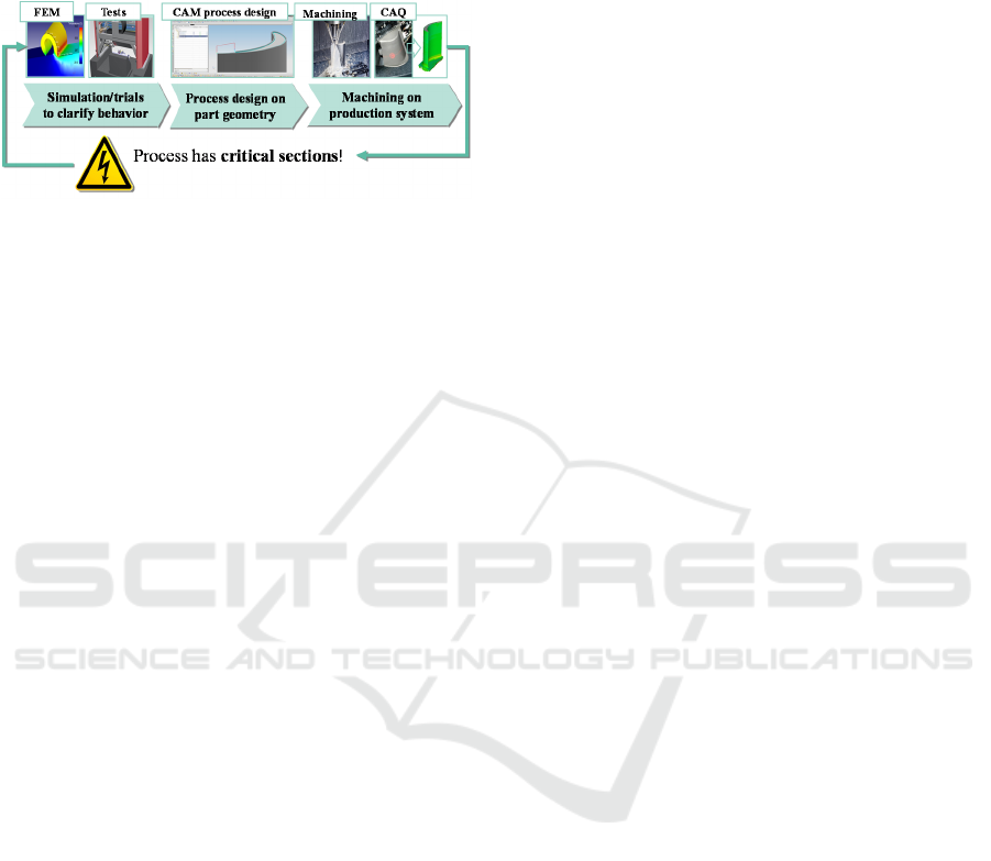
CNC machines. The G code contains all necessary
commands for the production and tells the NC
machine "what" must be done to manufacture the
product, see Figure 1.
Figure 1: Sequential CAx process chain for machining.
To enable automated production of components
on an NC machine, process conditions are analyzed
using Finite Element Methods (FEM), then the G
code is first checked and optimized by the machine
operator line by line on the machine. This phase of
the production is called the process “start-up” which
includes the so called “verification phase”, in which
the toolpaths are checked manually by the operator.
The current method for verifying the CNC process is
as follows: The operator loads the G-code, all
required tools and the workpiece manually into the
CNC machine and initiates the process. The resulting
machined part is then verified in a Computer Aided
Quality assurance step (CAQ). However, the current
procedure for verifying and optimizing the
production of components using CNC machines has
several drawbacks.
The verification phase currently takes about 60%
of the start-up phase (Arntz, 2013). Even under
optimal conditions, the verification phase has a large
impact on the overall process time and production
costs and is one of the highest cost factors for
production due to its susceptibility to errors. During
the start-up phase, no added value is created, while
the machine and the operator are completely
occupied.
The combination of the latest advances in AR,
sensors and networking, together with paradigms like
IoT, enable the development of advanced applications
for industrial systems (Yan, 2017). Among the
enabling technologies, industrial Augmented Reality
has proven to be a suitable tool for the manufacturing
strategies proposed by different countries (Suárez-
Albela, 2016). In this context, the following
assumption can be formulated:
An assistance tool that enables machine
operators to verify CNC processes handsfree during
the start-up increases productivity and is more
intuitive, while allowing the operator being fully
aware of their surroundings considering the
industrial configuration of the production field.
While measuring the productivity as an added
value of using an AR assistance tool needs several
field studies, there is a main research issue, which can
be derived from assumption:
How can machining processes be mapped in AR
glasses worn by the operator on the factory floor?
Answering this question involves the modelling
of machining process for AR glasses and the
realization of a communication to the AR device,
which allows a sufficiently accurate transmission of
process data, in particular simulated toolpath and the
contact conditions between the cutting tool and the
workpiece for multi-axis machining. The core
element for the communicating between the AR
glasses and the CNC machine is a reliable
mathematical representation of machine tools, which
can be used as a basis for industrial Augmented
Reality applications.
3 STATE OF THE ART
It is difficult to understand what is happening inside
the machine, as well as it is very difficult to combine
simulation data with real machining steps during the
process (Schug, 2015). Due to this lack of knowledge,
it is hard to recognize errors or malfunctions of a CNC
machining process. To compensate the gaps in error
recognition, production workers and operators often
decide between working at the machine or relying on
the computer-optimized data, that tells the operator
what is happening inside the machine. The critical
question “What is more reliable?” cannot be
answered clearly, because both sets of data, the real
machine data as well as the computer-generated data
reveal only one part of the machining process
(Minoufekr, 2014). While these two sets of data were
strictly separated in the past, modern technologies
arise, which can help to bridge these gaps by
approaches like “Digital Twin” (Ding, 2019)
In order to use process simulation on the shop
floor, Augmented Reality (AR) techniques are needed
to dynamically display relevant information to the
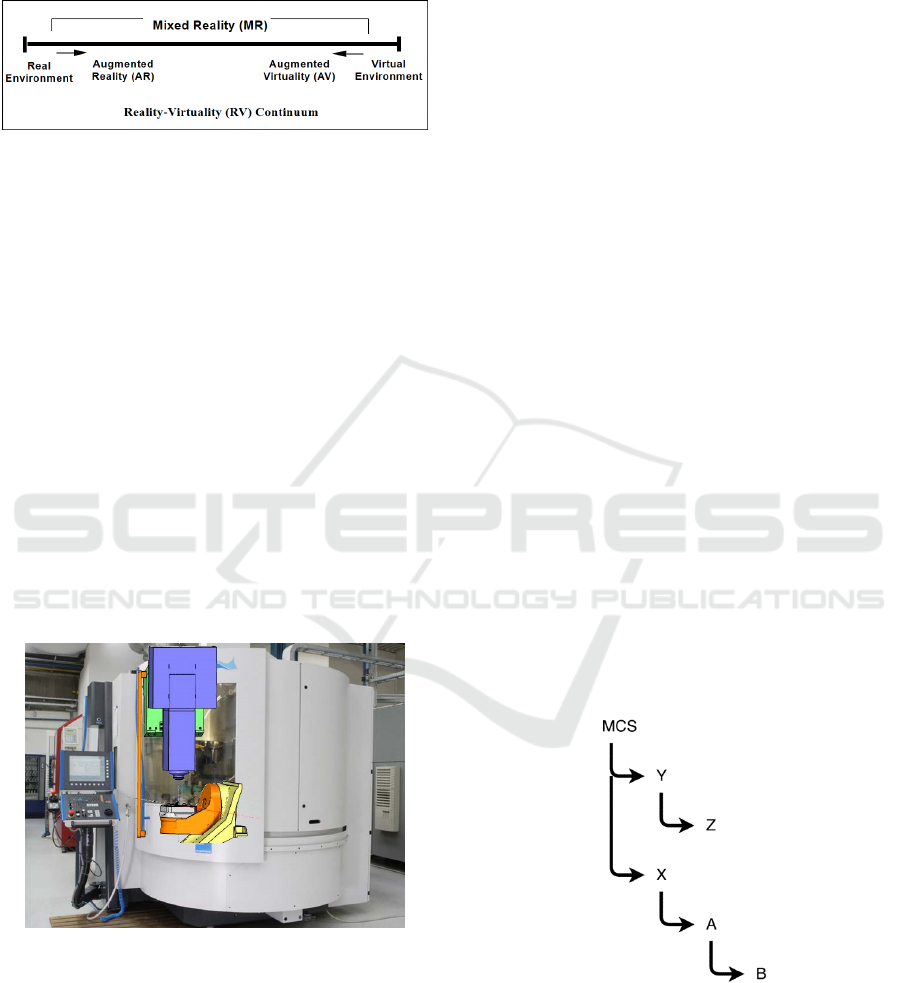
operator. Azuma (Azuma, 1997) describes AR as the
integration of 3D virtual objects into our real 3D
environment, see Figure 2. Virtual data is processed
and can be used or interacted with in real-time. With
this definition in mind, we can compare Virtual
ICINCO 2019 - 16th International Conference on Informatics in Control, Automation and Robotics
628
Reality (VR) and AR easily. While VR completely
relies on a virtual representation of the world, AR is
the step between VR and real life, where digital and
real objects are merged in real time.
Figure 2: Mixed Reality continuum defined by (Milgram
1995).
In the Hololens, the digital copy of the real world
is created by using sensory techniques, which can
scan the real world and transfer it into a mesh
representation. Holograms that are projected into the
real world can use the data of the virtual pendant. This
allows the device to mimic interaction from
holograms with real world objects (Microsoft, 2017).
This work will focus on the Hololens and therefore
act in the range of this specific MR or generally AR.
4 SOLUTION METHOD
The main goal of this paper is to discuss, CNC
machining processes can be modelled for AR devices,
see Figure 3. By using appropriate, knowledge-based
techniques, it is possible to enhance the process
quality to a higher accuracy level (Schug, 2012).
Figure 3: Expanding workers vision with AR.
Exploiting this idea, the solution path consists of
the availability of process design knowledge
providing process parameters, simulation data and
technology information during process setup in real-
time corresponding to the current process using the
Augmented Reality technology. Hence, this paper’s
focus is on how CNC simulations can be carried out
by using AR and more specifically, what is a
kinematic chain and how to mimic the kinematic
chain that every CNC machine inhabits to be
represented visually
.
4.1 Modelling of CNC Machine Tools
CNC machines are machine tools which have the
capability of producing high precision workpieces
using modern control techniques. In a CNC machine,
a toolpath for the workpiece is defined. The machine
rapidly checks the relative movement between
workpiece and working tool, which travels along the
toolpath. The machine continuously controls the
relative movement to correct position errors between
actual values and nominal values. There are different
types of CNC machines with different kinematics or
axis configurations, for example with head rotation or
with a rotating table (Altintas, 2012).
The kinematics of CNC machine tools can be
expressed by the coordinate systems of each machine
element of the machine, see Figure 4. The machine
coordinate system [MCS] is the root of the linked
coordinate systems. Every milling tool of the machine
has its own coordinate system and can have children.
The children are always moving relative to their
position in their parents coordinate system, which is
referred as a kinematic chain. If axis X is moved, the
table, which consists of axis A and B, moves as well.
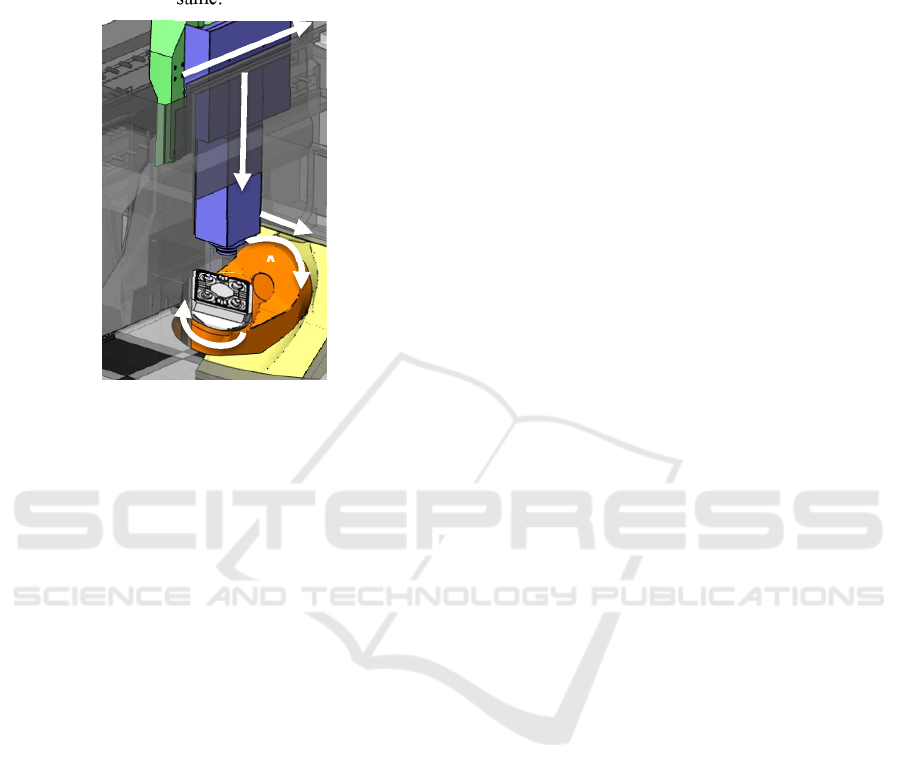
Figure 5 shows the according 5-axis CNC machine.
The different coloured elements, can move along
their axis into the according axis direction, namely X,
Y and Z. The rotating axis are A and B and allow the
machine to rotate according to the table of the
machine.
Figure 4: Coordinate system of a CNC machine.
In general, machine kinematics or a kinematic
chain can be described as a series of rigid bodies that
are connected with joints. Each machine parts
movement is restricted through the parent part’s
movements. Parts can be transformed.
Modelling of CNC Machine Tools for Augmented Reality Assistance Applications using Microsoft Hololens
629
Transformation are in machine kinematics either
translations, a movement, or rotations. When a parent
part is transformed, its children will take an according
transformation, so that the relative position to its
parent part is still the same.
Figure 5: Model of a CNC machine with its axis.
The position of every individual object can be
changed with rigid transformations. Rigid
transformations are transformations, rotations and
shearing, which can be formulated as matrices. Most
of the machines use the Cartesian Coordinate System.
In computer graphics, we use for the same
transformation the more user-friendly extended
coordinates. Extended coordinates have 4 entries and
the resulting matrices are 4x4 matrices. This allows to
define rotations together with translation in one single
matrix. Translating a point pos, where
,
(1)
about the amount of another vector tra, where
,
(2)
can be expressed as
100
010
001
0001
∙
1
1
(3)
The following matrix expresses the rotation of an
object around the z-axis. The angle α
determines the
amount of degree, the object is rotated:
cos sin 0
sin cos 0
001
(4)
To rotate an object around a normalized vector
rot, where
,
(5)
it is possible to calculate a matrix that transforms the
coordinate system, so that rot is the new rotation axis.
This can be done by calculating the orthonormal base
and writing its vectors into a new matrix T. After
applying the transformation, the transformation can
be inverted by multiplying it with its inverse T
-1
. For
rotation matrices, it is set that
, where T
T
is
the transposed matrix of T. This leads to the following
matrix for a rotation around an arbitrary axis x:
∙
∙
.
(6)
After introducing the basic mechanics, the
advantages of extended coordinates are evident. The
inner 3x3 matrix of a homogenous matrix allows to
rotate the object, while applying a simultaneously a
translation within the same matrix. The following
matrix rotates an object around axis R
z
, translates it
about tra and additionally scales it with factor s:
∙cos sin 0
sin ∙cos 0
00
0001
.
(7)
Using transformation matrices containing
homogeneous coordinates, translations become
linearly independent, and thus can be seamlessly
composed with all other types of transformations.
Although a translation is a non-linear transformation
in a 3D Euclidean space and cannot be combined with
other transformations while preserving
commutativity and other properties, it becomes, in a
4D projective space described by homogeneous
coordinates, a simple linear transformation. Thus all
affine transformations can be obtained by
composition of two or more affine transformations.
We can now stack different transformations, which
results in a complete transformation M, where
∙
∙
∙….
(8)
Z
Y
A
B
X
ICINCO 2019 - 16th International Conference on Informatics in Control, Automation and Robotics
630
However, Equation 8 is only true, if every element
in the kinematic chain of the machine tool is
expressed using the same coordinate system. While in
computer graphics applications this requirement may
be true, most machine tool kinematics are not
expressed using the same coordinate system. Usually
every part of the machine has its own coordinate
system, which is based on its origin, because the
movements of the single machine element are always
expressed relatively to their parent. For example, the
rotation table around B in Figure 5 always rotates
around its own y-axis, while its position and
orientation can change, when B is rotating. The
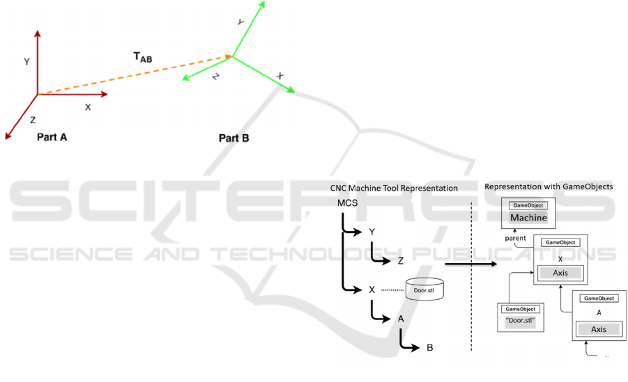
problem is explained in Figure 6.
Figure 6: Two machine elements and their individual
coordinate systems.
For finding the homogeneous matrix describing
different coordinate systems, it is enough to translate
every coordinate system, so that the coordinate
system of each element is based on the global
machine coordinate system. Hence, Equation 8 can
now be formulated as
∙cos sin 0
∙
sin ∙cos 0
∙
00
∙
0001
(9)
With this transformation all parts of the kinematic
chain can be converted to a transformation series of
rigid bodies, which are multiplied to one complete
transformation of the entire machine. The final matrix
M describes the complete transformation of the CNC
machine, for its individual part (Uicker, 2011).
4.2 Implementation of Machine Tool
Kinematics using Game Engines
Due to our focus on implementing an AR solution on
the Microsoft Hololens, it is important to note that
developing a basic kinematic chain on the Hololens
AR device can be realized most efficiently through
the Unity game engine (Huang, 2019). The
comparison between the Unity engine and other
frameworks like Unreal shall be neglected here and
might be a topic for further investigations. Due to the
native support for Hololens applications, the Unity
framework allows to access features like spatial
mapping or gesture control. Hence, the Hololens
paired with the Unity engine seems to be the current
state of the art for AR Hololens development and a
suitable basis to implement CNC machine
kinematics.
The basic structure of the kinematic chain is
established, as illustrated in Figure 7. Every child’s
transform is bound to the parents transform, while the
whole machine has one root object. For the kinematic
chain, the task is to find an implementation using
Unity. The Unity engine already has a structure,
which the kinematic chain can be easily based on. In
Unity, every scene is populated with so-called
“GameObjects”. These are hierarchically structured
and can be compared to a scene graph (Burns, 2004).
In a scene graph every object can have children or
parents. Every object holds its own transformation
matrix. If you manipulate an object, all the child
objects of the object are transformed with the same
matrix as well.
Figure 7: Transfer of the kinematic chain.
Unity also provides functions to translate and
rotate GameObjects. Translations can be performed,
regarding the local coordinate system of each
GameObject or to the global coordinate system.
Rotations can be done in regard to the local or the
world system, while they either rotate around the
centre of the model or a predefined point. We exploit
the scene graph structure to implement the
representation of machine kinematics. Using
GameObjects, it is not necessary to calculate a
specific matrix or translate objects into its parents
coordinate system. To implement the structure of the
machine tool, the realized framework parses the
machine kinematic recursively:
Modelling of CNC Machine Tools for Augmented Reality Assistance Applications using Microsoft Hololens
631
GameObject load_model ()
{
//Create a gameobject for machine
GameObject m = new GameObject(“r”);
//Load all axis
foreach (machine_axis a in m.axis)
{
load_axis (a, machine);
}
//Load all single models to unity
foreach (machine_def g in m.geometry)
{
loadgeo (g, machine);
}
//Return complete kinematic chain
return machine;
}
void load_ax(Axis a, GameObject p)
{
//Create an own gameobject for axis
GameObject ax = new GameObject(a.id);
//Attach it to the parents transform
axis.transform.parent = p.transform;
//Attach axis script to it
[ … ]
// load all children recursively
foreach(var c in a.Items)
{
if (c is Axis) load_ax (c, a);
elseif(c is Geometry) loadGeo(c,ax);
}
}
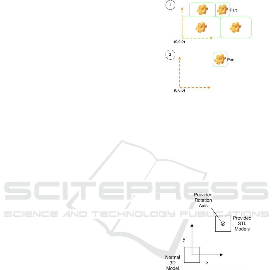
While this works perfectly with translation
commands, an unexpected behaviour regarding
rotation of machine parts can be observed, when the
CAD data of the machine elements are designed in
different coordinate systems. Usually, when creating
a 3D CAD model, it is cantered in the origin
O(0, 0, 0). However, most machine tool
manufacturers provide the CAD data in a different
spatial location. The 3D model of each machine part
is positioned at the unique location it would have,
relative to the entire machine tool setup, refer to
Figure 8. This makes one more information necessary
to be stored in the machine definition: the rotation
axis. Normally in Unity, if you rotate an object, you
either rotate it around the world origin or translate it
into the origin to rotate it around its centre.
Figure 8: Errors in machine representation due to incorrect
CAD modelling coordinate system.
However, in most cases machine parts
do not rotate around the origin, but a
specific rotation axis. This can be seen in Figure
9.
Unity solves this problem by providing
RotateAround(Vec3 po,Vec3 ax, float a)
,
which allows to rotate around a certain point and a
specified axis. Hence, it is enough to use this
function with
po
being the rotation point provided
in the machine definition and
ax
the according
rotation axis.
Figure 9: Illustration of model positioning.
4.3 Connectivity & Inclusion
Several implementation ideas for a connection and
transfer system to the Hololens are discussed. Some
of these played major roles:
Server system that runs directly on the Hololens
(asp.net or Appache)
Messaging middle-ware like DDS
Rest interface
Direct socket communication with own protocol
ICINCO 2019 - 16th International Conference on Informatics in Control, Automation and Robotics
632
During development, it appeared that most ideas
needed to be scrapped. While the Hololens runs
Windows 10, nevertheless, applications that are
developed for the Hololens are restricted to using the
Universal Windows Platform (UWP). UWP is a
sandboxed run-time environment that only runs
applications written in C# (Garofalo, 2013). UWP has
access to most functions of the .net software
framework by Microsoft but is partially restricted.
Due to the sandbox restrictions of the UWP, there are
currently no server systems or messaging systems
available that run on the UWP. Therefore, these ideas
could not be realized.
However, there exist some REST interfaces for
UWP, which allows to post and get data from a
remote device, with an URL based access system.
They only support post data in form of strings and no
direct binary upload. Because of this binary would
need to be transformed into some format which can
be put into a string. This can be done with a
serialization as for example the Base64 encoding.
This would make a lot of conversions necessary and
make the framework slow and hard to be included
into other systems. Therefore, the final decision was
to use a direct socket communication.
As base for the protocol the “Transmission
Control Protocol” (TCP) was chosen. The protocol
should consist of different parts in the header. Instead
of relying on a slow string base message approach,
integers will be used to encode the commands. Due to
the use of TCP sockets, a stream is used to write data
in. From the other side of the stream, data can be read
out. Because two-sided connection could be useful
later, when data from the Hololens should be sent to
the remote computer, two different modes should be
implemented. One mode is for sending files and
messages, the other one for receiving files and
messages on the server side. The other one sends a
starting signal to the Hololens to send its data to the
server. The server part decides whether the Hololens
can send its data or should queue up its message and
send them later.
The first and only mandatory part of the protocol
header is the command part. The sender decodes the
command for the device with help of a shared header
file. Currently, the framework only needs three
commands, one for sending a message, which is
stored in the memory. Another one for sending files
which are stored on the HDD directly. The last one is
for switching the mode from only receiving Hololens
to sending and therefore allows the Hololens to
transfer its queued data. While this implementation
uses only two commands, the header file can be
extended just by writing new commands into it. When
the protocol header is parsed, a call-back with the
according command is called, where you can simply
switch case over your own implemented commands.
To make a fast switch between sending and not-
sending mode of the Hololens possible, the header is
finished if the command is “SND” or “RCV”. There
is no need to write additional information in the
header (Figure 10).
Figure 10: The first part of the header, manages the
commands.
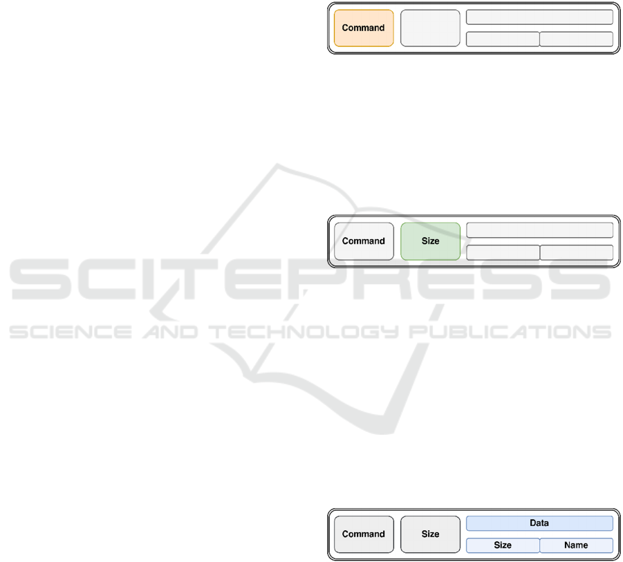
Because every message and every file have
different sizes, the next part of the header defines the
size of the attached data (Figure 11). This part of the
header is only used, if the command is a command
that indicates a data transfer. Otherwise the header
ends here.
Figure 11: The second part of the header, defines the packet
size.
The third part of the header contains data
(Figure 12). If the data consists only of a message, it
can be read straight away and stored into memory. No
further information is necessary. In the other case,
when the command, which stores data on the HDD, is
transmitted, the header needs to be extended. It will
be extended with two new parts, the first one being
the file name size of the file which is transferred and
the second one the file name. Through this the file can
be stored under correct name on the Hololens hard
drive.
Figure 12: The data part of the header can contain additional
information.
While the whole header is very small, it could be
optimized further. Figure 13 shows the complete
header file.
Modelling of CNC Machine Tools for Augmented Reality Assistance Applications using Microsoft Hololens
633
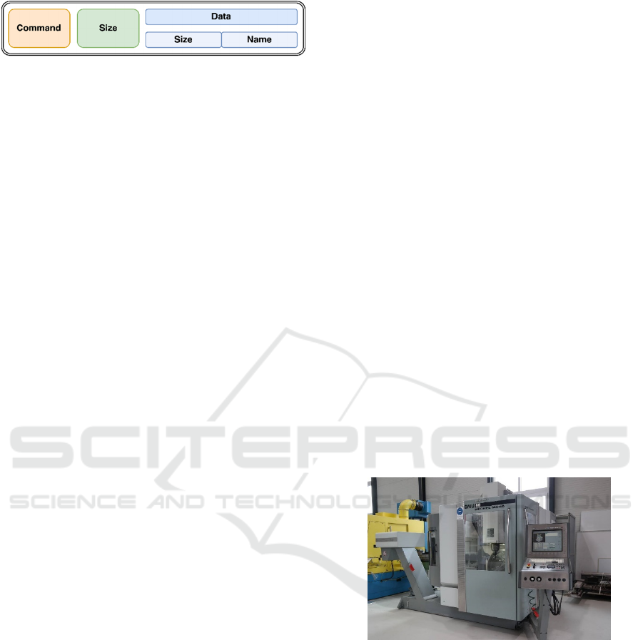
Figure 13: The whole protocol header.
The theoretical approach for the protocol header
above is implemented on the Hololens as well as a
server for testing the functionality. On the server side,
the connection is not very complicated. The server
opens a socket through the .net class TcpClient,
which handles the TCP specific connection setup.
The following code fragments are part of the class
TcpServer.cs, which is part of the Hololens
framework.
public void StartServer(port, size){
HostName h = new HostName (GetIP() );
StreamSocketListener s = new
StreamSocketListener();
IAsyncAction outstandingAction =
server.BindEndpointAsync (h , port );
}
Because any connection from any endpoint to the
Hololens is accepted, a socket listener needed to be
implemented. This listener waits for connection at-
tempts on a predefined port. As already stated earlier,
the Hololens only supports UWP applications. For
UWP applications, there is a provided class
“StreamSocketListener”, which can handle incoming
connections. After the listener registers a connection
attempt, it fires a call-back and gives this call-back to
the socket which can be used to read data from the
regarding stream. Once the call-back is received, a
reader for the created socket can be used to wait for
incoming data. For the implementation refer to the
next two code segments.
public async void ReadFromStream( ) {
awaitreader.LoadAsync (size_16);
int command = reader.ReadUInt16();
awaitreader. LoadAsync (size_32 );
UInt32 size = reader.ReadUInt32 ( );
switch (command){
case POST:
string path=awaitReceiveFile( size);
callback_post ( size, path );
break;
case INFO:
byte[]data2=awaitReceiveData( size);
callback_info ( size, data2) ;
break ;
case RCV:
callback_rcv();
break ;}
ReadFromStream ( ) ;}
The function ReadFromStream waits for available
data and parses the data accordingly to the protocol.
This happens asynchronously which means the call of
the function is not blocking but happens in a separate
thread in the background. Inside this function, three
different call-backs can be called. Any class can
extend TcpServer and overwrite the call-backs, to
manage the received data or to decide how data
should be sent.
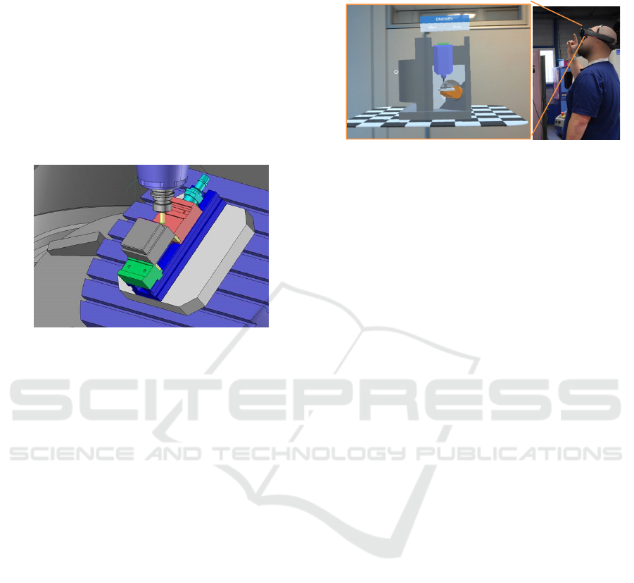
5 RESULTS AND DISCUSSION
Through Unity and a scene graph structure, a
straightforward approach is chosen to model
kinematic chains of CNC machine tools. We use an
DMU 50 eVolution by the manufacturer DMG Mori
is used to carry out the experiments in our current
setup, which is controlled and interfaced through a
Siemens 840D control computer, as shown in
Figure 14. The production engineers typically design
the machining process using a CAD/CAM (computer
aided design and manufacturing) software on a
designated computer. When the required process
design is completed, a CNC program is exported,
which specifies a toolpath for the machine tool and
thus directly controls the operation of the CNC
machine.
Figure 14: The CNC machines used for trials and
experiments.
To demonstrate the concept of linking simulation
data with AR glasses, a test geometry is defined. The
test part consists of simple geometric features. A
cuboid is machined on a rectangular base, Figure 15.
The used tool is a standard 10 mm diameter shaft mill
with four cutting edges.
While the program is running, the control
computer provides real-time access to relevant
measurements from the process, such as tool position
and orientation. Additional sensors for measuring
power, torque, forces and vibrations, can often be
installed in the industrial machines (Minoufekr,
ICINCO 2019 - 16th International Conference on Informatics in Control, Automation and Robotics
634
2013). In our setup, we did not consider
dynamometers or other sensor technologies.
The DMU 50 employs a control system, which
has limited capabilities for external connectivity. It
does however support Dynamic Data Exchange
(DDE), a legacy protocol for inter-application
communication. We use the DDE communication
over the network to access the current position of the
milling tool. An interface program handles the
communication with the machining centre’s control
computer, while streaming coordinate data over TCP
to subscribing PCs on the network.
Figure 15: The process design using the Siemens NX
CAD/CAM software.
One of the main requirements for AR-based
machining assistant is the ability to blend the user’s
view of the real environment with overlaid virtual
imagery of the process. In our use case holographic
optical machine elements of the DMU 50 are overlaid
onto the Hololens headset, while the machine’s safety
glass is covered with coolant fluid, which allows the
machine operator to simultaneously see the real
environment, as well as superimposed 3D graphics,
see Figure 16.
We currently use the Hololens Version 1 model
with a native viewing angle (FoV) of 30°. A higher
FoV of at least 60° is desirable in our trials, since it
allows the operator to view the entire machine setup
in AR. The current FoV of Hololens Version 1 has the
ability to create extremely bright graphics, however
the AR content visible to the operator is too small at
the moment. Furthermore, the visualization of
sections with rather high details can be optimized in
order to increase visual geometry quality.
The ability to provide real-time visual feedback to
the operator is specifically useful when the operator
designs a new program or modifies existing ones.
Experimentations and research with different tools
and materials can also benefit from a better
understanding of the current state of the operation.
The visualization of process data directly in the
workspace reduces mental load for the operator and
provides intuitive access to the information.
Figure 16: The operator views the machine operation
through the Hololens, which is projecting stereoscopic
images, augmenting the operator’s view of the process with
relevant information.
One particularly interesting property of Hololens
is the ability of reducing the impact of occlusion and
enhancing the visibility of real-world objects. In the
case of machining processes, it might be difficult to
see the tool as the cutting tool is covered by the
workpiece. Particles, such as swarf or cutting fluids,
can also reduce the visibility or there is no visibility
at all. The ability to render bright 3D graphics at any
location in the workspace always makes it
straightforward to indicate the tool position.
6 CONCLUSION AND FUTURE
WORK
In our system, we visualized the production
machine’s dynamic behaviour during the
manufacturing process using AR glasses. We also
provide a 2D overlay of the CNC toolpath, projected
on the AR device.
This paper focussed mainly on the
implementation of the kinematic chain for CNC
machines. The representation of kinematic chains
was introduced as computer graphic GameObjects.
Using basic rigid body transformations, like
rotation or translation provide the basic
mathematical tools to describe the dynamic
behaviour of a machine tools and its sub-elements.
These mathematical concepts can directly be
implemented in scene graphs like Unity, which
allows projecting the machine tool behaviour in
AR. After illustrating the actual implementation of
the kinematic chain in Unity, an experiment was
carried out using a CNC machining centre.
The interactive visual feedback using our AR
platform is valuable technology in training and
education. In the current system, we merely highlight
Modelling of CNC Machine Tools for Augmented Reality Assistance Applications using Microsoft Hololens
635

the current CNC operation, but in the future, an CNC
interpreter could analyse the motion sequence of the
tool and allow the system to support the operator and
process designer. The operator would for example be
able to simulate the process with a virtual tool and real
workpiece, real tool and virtual workpiece, or with
both a virtual tool and virtual workpiece. This could
be powerful in online programming, providing a safe
and direct mechanism for iterative program
development with real-time visual feedback. The
simulator would also save time since the operator
could jump to any part of the program, having the
ability to fast forward or reverse the process.
The interpreter would be useful for real-time
operation, making it possible to visually indicate the
past and future trajectory of the real tool using motion
vectors. The operator could thus easily see the tool’s
expected position for a few seconds ahead of time. By
visualizing the complete tool trajectory of the
program, we could increase safety, by visually
making sure that the tool does not exceed any
geometrical bounds.
ACKNOWLEDGEMENTS
The authors would like to thank the INTERREG V A
de la Grande Région for the support of the depicted
research within the PRODPILOT project. The authors
also thank Dropslab Technologies for providing the
HoloConnector platform and the invaluable
discussions, suggestions and technical assistance with
the industrial implementation.
REFERENCES
Altintas, Y., 2012, Manufacturing automation: Metal
cutting mechanics, machine tool vibrations, and CNC
design, 2nd edn., Cambridge University Press,
Cambridge, New York.
Arntz, K., 2013, Technologie des Mehrachsfräsens von
vergütetem Schnellarbeitsstahl, Aachen
Azuma, R., 1997, A survey of augmented reality. Presence:
Teleoperators and virtual environments, 6(4):355–385.
Burns, D., Osfield, R., 2004, Tutorial: open scene graph A:
introduction tutorial: open scene graph B: examples
and applications. In Virtual Reality, 2004. Proceedings.
IEEE, pp. 265–265. IEEE.
Schug, P. et al, 2012, Durchgängige CAx-Prozessketten,
Forschung an der Werkzeugbau Akademie, Apprimus,
Aachen
Ding, K., Chan, F., Zhang, X., Zhou, G. & Zhang, F., 2019
Defining a Digital Twin-based Cyber-Physical
Production System for autonomous manufacturing in
smart shop floors, International Journal of Production
Research
Milgram, P., Takemura, H., Utsumi, A. and Kishino, F.,
1995, Augmented reality: A class of displays on the
reality-virtuality continuum, Photonics for industrial
applications, pp. 282–292. International Society for
Optics and Photonics.
Ohta, Y. and Tamura, H., 2014, Mixed Reality: Merging
Real and Virtual Worlds. Springer Publishing
Company, Incorporated, 1 ed.
Yan, J., Industrial Big Data in an Industry 4.0
Environment: Challenges, Schemes, and Applications
for Predictive Maintenance, IEEE Access, vol. 5, pp.
23 484-23 491, 2017.
Suárez-Albela, M., Fraga-Lamas, P., Fernández-Caramés,
Dapena, T: M. and González-López, M., Home
Automation System Based on Intelligent Transducer
Enablers, Sensors, vol. 16, no. 10, p. 1595, Sep 2016.
Garofalo, Emanuele, A. Liccardi and M. Aponte. 2013.
Windows Runtime Environment, pp. 31, 72. Apress,
Berkeley, CA.
R. Drath and A. Horch, “Industrie 4.0: Hit or Hype?” IEEE
Industrial Electronics Magazine, vol. 8, no. 2, pp. 56–
58, June 2014.
Microsoft, 2017. Microsoft HoloLens. Website. Retrieved
January 23, 2017, from https://www.microsoft.com/
microsoft-hololens/en-us.
Minoufekr, M., Glasmacher,L., Adams, O., ‘Macroscopic
Simulation of Multi-axis Machining Processes’, 10th
International Conference on Informatics in Control,
Automation and Robotics (ICINCO 2013), 505–516.
Minoufekr, M., Schug, P., Joshi, M., Process
Characterization and Evaluation of NC Machining
Processes based on Macroscopic Engagement
Simulation, 11th International Conference on
Informatics in Control, Automation and Robotics
(ICINCO 2014).
Uicker, J., Pennock, R., Shigley, J., 2011. Theory of
machines and mechanisms, vol. 1. Oxford University
Press New York.
Huang, L., Collins, S., Kobayashi, L., and Sgouros, T.,
Shared visualizations and guided procedure simulation
in augmented reality with Microsoft HoloLens, Proc.
SPIE 10951, Medical Imaging 2019: Image-Guided
Procedures, Robotic Interventions, and Modeling,
1095112
ICINCO 2019 - 16th International Conference on Informatics in Control, Automation and Robotics
636
