
Multiple DOF Platform with Multiple Air Jets
Shinya Kotani
1
, Nobukado Abe
1
, Satoshi Iwaki
1
, Tetsushi Ikeda
1
and Takeshi Takaki
2
1
Systems Engineering Robotics Laboratory, Graduate School of Information Science and Technology,
Hiroshima City University, Asaminami, Hiroshima, Hiroshima Prefecture, Japan
2
Hiroshima University, Graduate School of Engineering, Hiroshima, Japan
Keywords: Air Jet Manipulation, 3D Space, Multiple DOF Platform, Control.
Abstract: We have been studying noncontact object manipulation technology in which a single ball-shaped object is
floated and controlled for its 3D position with multiple air jets driven by a pan-tilt actuator. In this paper, we
try to control position and orientation of an arbitrary shaped object. Here an arbitrary object is connected with
a triangle platform which is composed of three spheres linked with thin wires. Each sphere is spatially
controlled by an air jet unit which consists of an air jet on a pan-tilt actuator. Kinematics of the air jet platform
as a parallel link mechanism is calculated and a control method for the air jet platform is proposed.
1 INTRODUCTION
Non-contact object manipulation technology has
excellent features such as frictionlessness,
transparency, cleanliness, etc. because it does not
require a transmission mechanism, and various
studies have been advanced in recent years.
Until now,
non-contact object manipulation technology using air
jet has been reported object manipulation technology
(Matsushita et al., 2014) (Matsushita et al., 2016) (T.
Yamamoto et al., 2009) on a plane as manipulation
technology to control position and posture in two
dimensions.
Further, in the operation technique in a
three-dimensional space, there is a single nozzle
operation method (Becker, A. et al., 2009) using a pan
and tilt actuator. As a transfer technique using a
plurality of nozzles, a relay transfer method
(Yoshinaga et al, 2018), a pitching catch method (Abe
et al, 2018) and the like have been reported. However,
in these methods, the shape of the object that can be
manipulated is limited to a specific shape such as a
cylinder, square pole, or sphere. In essence, it is
impossible to manipulate
three translational DOF +
three rotational DOF
in a three-dimensional space of
an arbitrarily shaped object. Therefore, in this
research, we change the viewpoint and give up the
complete non-contact operation of the object itself.
Instead, we try the non-contact 6-DOF control of the
platform which is the base to attach the arbitrarily
shaped object. Specifically, a structure (called Air jet
platform) in which a plurality of spheres are
connected by a high rigidity wire is configured, and
the three-dimensional position of each sphere is
controlled by a dedicated air jet mounted on a pan and
tilt actuator. We propose a method to control the
position and attitude of the air jet platform with 6-
DOF.
In this paper, we clarify the mechanism,
kinematics and control method when using the
minimum three spheres, and confirm the
effectiveness of these by experiments.
2 RELATED RESEARCH AS FOR
AIR JET MANIPULATION
2.1 On a 2D Plane
On a flat plane, the 3-DOF (two translational DOF +
one rotational DOF) control method for a single
object by changing the flow rate and angle of four air
jet nozzles has been proposed (Matsushita et al.,
2014) (Matsushita et al., 2016). In these technologies,
wind force applied to an object is approximated as a
linear lumped constant system without distance
dependence. And because it is unilateral actuation,
they prepared an air jet nozzle which is one or more
than the object control degree of freedom, and solved
this redundant DOF problem by linear programming.
Eventually the feedback controllers were
independently adopted for each DOF.
Kotani, S., Abe, N., Iwaki, S., Ikeda, T. and Takaki, T.
Multiple DOF Platform with Multiple Air Jets.
DOI: 10.5220/0007931704310436
In Proceedings of the 16th International Conference on Informatics in Control, Automation and Robotics (ICINCO 2019), pages 431-436
ISBN: 978-989-758-380-3
Copyright
c
2019 by SCITEPRESS – Science and Technology Publications, Lda. All rights reserved
431
2.2 In a 3D Space
In three-dimensional space, a 3-DOF operation
technique (Becker, A. et al., 2009) by a single air jet
nozzle mounted on a pan tilt actuator has been
proposed. In order to expand the motion space of the
object, (Becker, A. et al., 2009) has been drastically
modified with multiple air jet units, such as relay
transport method (Yoshinaga et al, 2018) and pitching
catching method (Abe et al, 2018).The decisive
difference from the above two-dimensional plane
problem is to actively utilize the Coanda effect. The
Coanda effect is a hydrodynamic property as
represented a phenomena in which a smooth convex
shaped object in a jet stream will stay in its stream.
The object can be passively floated in the air because
the wind force, gravity force and the restoring force
by this Coanda effect are naturally balancing. Then,
by moving the pan tilt actuator, two argument angles
on a spatial polar coordinate system are actively
controlled. On the other hand, regarding the jet stream
direction, a position feedback control system is
constructed in which the distance between the nozzle
and the object is measured and the air jet flow rate is
manipulated as a control input. In this way, total
translational 3 DOF is actively controlled. However,
with these methods, only position control of an object
in space is possible, and attitude control is impossible.
Moreover, available shape of the object is limited to
smooth convex shape.
Here, 6-DOF can be controlled by a drive
mechanism called Stewart platform (Stewart, D.
1965–1966) that can control the position and attitude
of an arbitrary object placed on the platform. The
platform and the six translational actuators are
mechanically coupled at a universal joint. Also, there
is a drawback that it is difficult to take a large drive
range of the table because it is necessary to avoid
collisions between the actuators. Compared with this,
our air jet platform has a much lower payload, but it
does not require a thick rod, so it can take a wider
range of motion. And it has the advantage that there
is nothing to block the view between the stator and
the rotor.
3 PROPOSAL OF STRUCTURE
AND KINEMATICS
3.1 Coordinate System and Geometric
Analysis
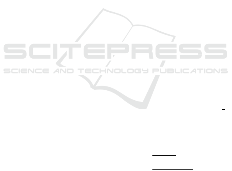
Fig. 1 and Fig. 2 shows a proposed structure of the air
jet platform and its coordinate system respectively.
is a platform coordinate system fixed to the center
of gravity
of the equilateral triangular platform of
side
.
is a base coordinate system fixed to the
center of gravity of an equilateral triangle with
three air jet nozzles of side
.
is fixed to the -th
nozzle. The x-axis of all coordinate systems is parallel
to the base of each triangle. In the following,
assumes the values 1, 2, and 3. A position vector
representing each vertex
of the platform in the
coordinate system
is represented as
. In
addition, position vectors when the center of gravity
of the platform, each vertex
of the platform, and
the vertex
of the base are viewed from the
coordinate system
are denoted as
,
,
and
, respectively. Assuming that the attitude of
the platform coordinate system is
, the
geometrical relationship with
is obtained, when
the homogeneous transformation matrix
from
the coordinate system
to the coordinate system
is given. First, since the origin
of
is the
barycentric position of
,
and
, the following is
obtained.
3
(1)
The attitude matrix
of the platform is
expressed as follows from Fig. 2.
⋮
⋮
∈
Here,
is in the same direction as
of
size
, and
is in the same direction as the
composite vector of
and
.
The magnitude of the composite vector is
√
3
according to the Pythagorean proposition. Also, since
is a right-handed orthogonal coordinate system,
can be represented by the outer product of
and
.
2
√
3
(2)
(3)
(4)
Since the coordinate system
is translated from
coordinate system
by
in parallel, each
vertex
of the platform viewed from the coordinate
ICINCO 2019 - 16th International Conference on Informatics in Control, Automation and Robotics
432
system
is expressed as follows.
(5)
Figure 1: Structure of the base and the platform.
Figure 2: Coordinate system of the base and the platform.
Figure 3: Pan-tilt actuator and coordinates.
3.2 Forward Kinematics Solution
The proposed mechanism can be considered as a kind
of parallel link mechanism. That is, the three air jet
streams are considered to be links with adjustable and
flexible length and pan tilt angle respectively. Here
we consider a forward kinematics problem with the
position and attitude of the platform as output, with
the position of each sphere as input. Each sphere
position
of the platform is at the vertex of an
equilateral triangle of one side
,
the following
constraints are satisfied.
(6)
The position and orientation of the platform can
be expressed as (7) if
is arbitrarily determined
within the range of this constraint. However, each
element of Eq. (7) is given by (1) (2) (3) (4).
01
(7)
In practice, it is difficult to extract an independent
variable from the constraints in (6), so it is difficult to
find a solution of forward kinematics easily.
Fortunately, from the viewpoint of mechanism
control, the following inverse kinematics is more
important than this forward kinematics, and its
solution is simpler.
3.3 Inverse Kinematics Solution
Kinematics is the problem of finding the pan-tilt angle
of each nozzle and the air jet stream distance hereinafter
referred to as the nozzle variable
,
,
when
is given. In order to do that, we first
calculate
,
,
and
. The following is
obtained from the linear simultaneous equations of
(1), (2), and (3).
√
3
(8)
2
2
√
3
(9)
2
2
√
3
(10)
Assuming that the solution of the equations (8), (9)
and (10) is
,
,
for simplification, the
nozzle variable B is as follows from Fig 4.
=
(11)
The above is the solution of inverse kinematics.
Multiple DOF Platform with Multiple Air Jets
433
4 PROPOSAL OF CONTROL
METHOD
Based on the solution of inverse kinematics obtained
above, the feedback control law independent of each
nozzle is determined.
4.1 Air Jet Flow Rates
Each air jet flow rate
is calculated by the following
PID control operation. Where
is the current
distance of the air jet stream and
is the target
distance.
(12)
4.2 Nozzle Angle
,
Set the angle target value of the pan and tilt actuator
as follows.
,
=
,
(13)
5 DEMONSTRATION
EXPERIMENT
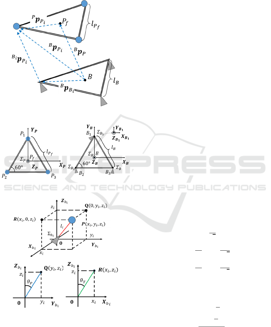
5.1 Outline of Experiment
In order to verify the validity of the proposed method,
we constructed an experimental system (Figs. 4). In
Figure 4: Overviews of the experiment system.
this experiment, we confirmed the operation of
translation and rotation of the air jet platform. At this
time, the movement locus was confirmed from the
distance sensor and the pan and tilt actuator. The
outline of the experimental setup is as follows.
5.2 Experimental Result and
Consideration
Fig. 5 show the position of the center of gravity of the
platform and the trajectories of each sphere when
translated 100 mm in the x-axis direction. At this time,
the motion on the actuator side performs feedback
control so that the air jet rotates at a constant z
coordinate while rotating the pan tilt so that the nozzle
tilts in the positive direction of the x-axis. The graphs
in Figs. 6 and 7 show the trajectories in the x-axis and
z-axis directions, and it is clear that they converge to
the target position (red line).
Figure 5: The platform translated +100 [mm] parallel in the
X-axis direction.
Figure 6: Time responses of the platform COG with respect
to X and Z axis.
ICINCO 2019 - 16th International Conference on Informatics in Control, Automation and Robotics
434
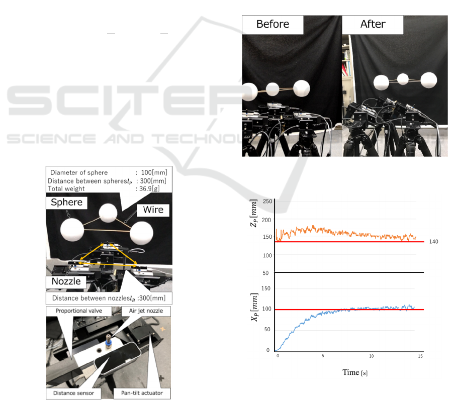
Figure 7: Time responses of each sphere with respect to X
and Z axis (sphere 1, 2 and 3 from above).
Fig. 8 show the trajectory of each sphere and the
rotation angle when rotating 30 degrees around the z-
axis. At this time, on the actuator side, the air jet
performs feedback control so that the z coordinate
becomes constant while rotating the pan and tilt so
that the nozzle tilts in the z-axis positive direction.
The graphs in Fig. 9 and 10 shows the z-axis rotation
and the trajectory in the z-axis direction, and it can be
seen that the target angle and target position (red line)
converge to some extent.
As a result, both parallel movement and rotational
movement were confirmed to be successful.
Figure 8: The platform rotated +30 [degrees] around the
-axis.
Figure 9: Trajectories of each sphere in XY plane.
Table 1: Outline of experimental equipment.
Product name and remarks
Control computer
Microsoft Windows10 Home 64bit
CPU:Intel® Core™ i7-7700 @
3.60GHz
Proportional solenoid
valve
MPYE-5-1/8-HF-010-B(FESTO)
Distance sensor Leap Motion
Pan-tilt actuator PTU-D46-70
Air nozzle
KN-Q06-20( SMC)
N
ozzle diameter:2.0mm
Air compressor
PO-0.75PGS6
(Hitachi Industrial Equipment
Systems Co,Ltd.)
Out put:0.75kW
Max pressure:0.93MPa
Air jet platform
Total weight : 36.9g
Sphere diameter : 7.5mm
Sphere weight: 10.2g
Multiple DOF Platform with Multiple Air Jets
435
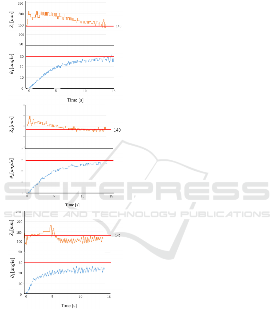
Figure 10: Time responses of each sphere with respect to
translation and rotation of Z axis (sphere 1, 2 and 3 from
above).
6 CONCLUSION
A platform was constructed by connecting multiple
spheres with high rigidity wire, and a method to
manipulate 6-DOF of the platform was proposed by
controlling the three-dimensional position of each
sphere with a dedicated air jet mounted on a pan-tilt
actuator. For the case of three spheres as an example,
we clarified forward kinematics, inverse kinematics,
and control methods, and confirmed the validity of
the proposed method by experiments.
In the future, we will improve the control
performance of this system and challenge the drive
system that enables endless rotation in various
directions by increasing the number of spheres. This
allows a 360-degree rotatable 3D digitizer. And, we
will consider applications such as video content
creation device that floats an arbitrary shaped object
in the air.
REFERENCES
Stewart, D. 1965–1966. “A Platform with Six Degrees of
Freedom”. Proc. Institution of Mechanical Engineers
(UK) 180 (Pt 1, No 15).
Becker, A., et al., 2009. Automated Manipulation of
Spherical Objects in Three Dimensions Using a
Gimbaled Air Jet, Proc. of IROS, pp.781-786.
T. Yamamoto, T, Takaki, et al., 2009., Non-contact
manipulation on flat plate using air-jet streams,
Transactions of the RSJ, Vol.27.
T. Matsushita, T. Sugiyama, et al., 2014. “Contactless
object manipulation using multiple air jets on planar
surface (Experimental case studies for small control
range with continuous air jets),” Transactions of the
JSME, Vol.80, No.817.
T. Matsushita, N. Tsuchihashi, S. Iwaki, T. Takaki., 2016.
“Contactless object manipulation using multiple air jets
on planar surface (Experimental case studies of control
method for the multiple objects using four air jets
nozzles)”DOI:10.1299/transjsme.15-00459.
Abe , Yoshinaga , Iwaki et al., 2018. “Pitching and
Catching of an Object between a Pair of Air Jet”,
ICINCO 2018,Vol 2,pp313-317
Yoshinaga ,Iwaki,Abe et al., 2018. “A Spatial Motion
Control to Transfer an Object between a Pair of Air Jet”,
ICINCO 2018,Vol 2,pp131-135
ICINCO 2019 - 16th International Conference on Informatics in Control, Automation and Robotics
436
