
I-AM: Interface for Additive Manufacturing
Marco Rodrigues
1,2
, Jo
˜
ao Paulo Pereira
1 a
and Pedro Miguel Moreira
2 b
1
INEGI – Instituto de Ci
ˆ
encia e Inovac¸
˜
ao em Engenharia Mec
ˆ
anica e Engenharia Industrial, Univ. do Porto, Portugal
2
ARC4DigiT, Applied Research Center for Digital Transformation, Instituto Polit
´
ecnico de Viana do Castelo, Portugal
Keywords:
Human-Machine Interface, Smart Industry, Industry 4.0, User-centered Design, Web based Interfaces,
Additive Manufacturing.
Abstract:
The shift of the computational paradigm to a model where there is a multiplicity of computational devices ca-
pable of feeling and acting on the environment allied to the digital transformation of manufacturing processes,
with an increasing real-virtual fusion, are two of the pillars of the ongoing industrial revolution industry coined
as Industry 4.0.
In the context of new manufacturing environments, the development interfaces that are usable, intelligible,
interactive and easy-to-implement and deploy across multiple device is a major aspiration to be achieved.
This paper describes the design process of an interface, supported by web standards, adapted for additive man-
ufacturing appliances. This interface aims to allow the monitoring of the production parameters, providing
the operator with all the information related to the manufacturing process and the equipment and materials
involved. Beyond providing an effective tool to monitor and control of the real manufacturing process, it also
allows to virtually simulate the process, thus enabling optimization and anticipation of possible issues.
The adopted user-centered design methodology is described, as well as the proposed architecture. Details are
presented on the developed prototypes, the users studies, and about the information collected from users for
the requirements elicitation process and from the tests. The interface was developed through several iterations
and was evaluated very positively by the users (operators) using established usability assessment instruments
and methods.
In the near future it is intended to generalize the approach and architecture to move towards a framework
dedicated to the design and implementation of universal interfaces for industrial environments.
1 INTRODUCTION
In recent years there have been lively technological
developments, and thus the integration of new tech-
nological trends has become natural in any area or
sector that benefits from them. Emerging paradigms
and technologies such as pervasive computing, au-
tonomous agents, augmented reality, virtual reality,
among others, tend to be exploited and integrated in
all sectors of the industry.
There is a sustained motivation to increasingly
venture on new technology solutions since the ex-
pected earnings are huge and the changes are fast.
Human-Machine Interfaces (HMIs) for manufactur-
ing process control are no different from other areas
and can greatly benefit from the integration of various
technologies.
a
https://orcid.org/0000-0003-2681-147X
b
https://orcid.org/0000-0001-8371-0347
HMIs are used on a daily basis for a variety of
purposes, such as in: cars - to provide driver infor-
mation about the trip, motor parameters, and extras
such as air conditioning or radio; medical equipment
- to provide information about the patient and to allow
some action by the patient’s condition; in the industry
- to provide information about a manufacturing pro-
cess and to allow control thereon.
In the industrial context different manufacturing
processes have different needs from the control and
automation point of view. One of the main objectives
of HMIs in industrial contexts is to provide correct
information to the operator and to enable it to assist in
the normal operation of the processes or in situations
of failure (Hollifield et al., 2008).
A well-designed HMI can lead to large benefits,
for example in the case reported in (Errington et al.,
2005), where the redesign of an HMI resulted in an in-
crease of more than 5 times the number of anticipated
fault situations and an increase of 37% in success rate
Rodrigues, M., Pereira, J. and Moreira, P.
I-AM: Interface for Additive Manufacturing.
DOI: 10.5220/0007933406450652
In Proceedings of the 16th International Conference on Informatics in Control, Automation and Robotics (ICINCO 2019), pages 645-652
ISBN: 978-989-758-380-3
Copyright
c
2019 by SCITEPRESS – Science and Technology Publications, Lda. All rights reserved
645

in the treatment of malfunctions.
The work reported here arises from an innovative
project that aims to investigate the process of addi-
tive manufacturing in an industrial environment using
thermoplastic materials for high temperature and re-
sistance applications, a process that has very specific
needs regarding the control of the equipment and pro-
cess monitoring.
Additive Manufacturing (AM), also known as
Addition of Material, is a manufacturing process
whereby a product can be directly manufactured from
a 3D model, allowing the production of a very wide
range of forms. The techniques of manufacture by
addition of material, in counterpoint with more tra-
ditional processes of subtraction, have several advan-
tages. It is the process used in most 3D printing de-
vices.
This work aimed to develop an HMI, based on
web technologies, customized for an additive manu-
facturing equipment. The HMI shall allow preview-
ing, monitoring and manipulation of its parameters
by providing the operator with a tool capable of pro-
viding in real time all the information concerning the
manufacturing process as well as the equipment itself
and shall allow the control through functions specifi-
cally designed for that purpose.
2 RELATED WORK
A main goal of this work is to devise an easy to de-
velop and easy to deploy interface. The system should
be able to integrate easily, being able to convey infor-
mation from/to the myriad of computational devices
on an industrial plant. With this goal in mind, stan-
dard web technologies became a rational choice due
the cross platform / media support for the interfaces,
the large support of tools and languages and the easy
integration via services or APIs on top of reliable and
available internet protocols.
The following text on this section describes some
of the most relevant examples found in the literature
regarding the use of web technologies for the imple-
mentation of HMIs in industrial processes.
A case study, described by Kacur et al. (Ka
ˇ
cur
et al., 2013), a PLC (Programmable Logic Controller)
was used as a web server and allowed to remotely
monitor a physical process. By taking advantage of
the capabilities of web technologies, monitoring can
be done remotely, anywhere on the planet, provided
they have access to the internet. In this case, two
physical processes were used for remote control: steel
coil winding and coal gasification, in which both tem-
perature values were monitored.
Another noticeable implementation of a web-
based system for control and automation was pre-
sented by Bermudez-Ortega et al. (Bermudez-Ortega
et al., 2016). In this case, a system was devel-
oped based on web technologies for remote control
of PLCs from a control laboratory through a browser.
The system consists of a Beckhoff manufacturer’s
PLC with Twincat software, which allowed running
control experiments in a laboratory. As a webserver
they used Node.JS which has an implementation that
allows connectivity to Twincat and on the frontend
of web application with a dedicated library : Easy
Javascript Simulations (EjsS).
Another work that is relevant to the subject and
that relates to the previous case is described by Li
and Zhang (Li and Zhang, 2011) where a system is
described to carry out remote control experiments in
a PLC. The developed system included a pneumatic
manipulator as control object, connected to the PLC
(Siemens model S7-224 PLC). It contained a net-
work card and was ethernet-connected to a server with
Windows 2000 operating system and STEP7-Micro /
WIN32 software installed. This software is also from
the Siemens manufacturer and serves for the purpose
of developing automation projects. The server in turn
was connected to a network hub that allowed remote
access by clients on the internal network and on the
internet.
A Final example is the Eiger software (Mark-
forged, 2018) providing remarkable features as:
• Access through any device with a browser;
• Import of 3D models / drawings to be printed;
• Print layers preview;
• Able to edit some properties such as dimensions,
positioning, material, etc.
• Real-time print parameter monitoring;
• Store and preview previously printed parts;
• 3D and 2D part display;
3 PROPOSED ARCHITECTURE
3.1 Architecture
The proposed general architecture follows a multi-tier
architectural model. In the particular case we identify
5 fundamental layers.
Sensing/Actuation Layer
Composed by all the apparatus that compose the
additive manufacturing appliance, including sen-
sors and actuators;
ICINCO 2019 - 16th International Conference on Informatics in Control, Automation and Robotics
646
Connectivity Layer
Implementing the communications protocols and
network infrastructure (HTTP, MQTT, sockets,
etc.);
Data Integration Layer
This layer responsibility is concerned with data
integration from several sources, persistence and
data processing (e.g. time series)
Application Layer
The application layer implements the main logic
and data access and processing. Exposes data ac-
cess and functionality via RESTful services. Also
enables subscription to real time services using
web sockets that enable two way communication
between the application and presentation layer;
Presentation Layer
This layer comprises the front-end modules and
applications, intended to be executed by a web
browser. Web standard client side technologies
such as HTML5, CSS and JavaScript are the sup-
porting technologies, although front end frame-
works and libraries can be integrated. Presen-
tation is intended to be cross platform and re-
sponsive to several devices specific characteristics
(size, colors, etc.).
In our specific instance of the proposed architec-
ture, the interface is fetched by a web browser that
loads all the resources needed to start the HMI. In
addition to HTML (structure and content) the loaded
web page incorporates by reference CSS (presenta-
tion) and Javascript / Ember.js (communication, in-
teraction, and behavior) documents. Ember.js was the
front-end framework selected for creating web inter-
faces using Javascript.
Real time services are subscribed using Socket.IO
library which enables real-time, bidirectional and
event-based communication between the browser and
the server.
The web server was implemented in Node.js and
making use of the express.js frameworks and the
ADS.js module. The latter enables communication
with automation software via TCP/IP.
At the integration layer we opted to incorporate
the Twincat automation solution from Beckhoff man-
ufacturer, which enables you to develop automation
solutions as well as communicate with hardware de-
vices that are connected to the system, such as motor
drives, PLCs (Programmable Logic Controller or Pro-
grammable Logic Controller) , input/output channels,
etc. This software has a modular architecture that al-
lows to deal with each module (consisting of software
and possibly hardware device) as a stand-alone de-
vice. The messages between the modules are made
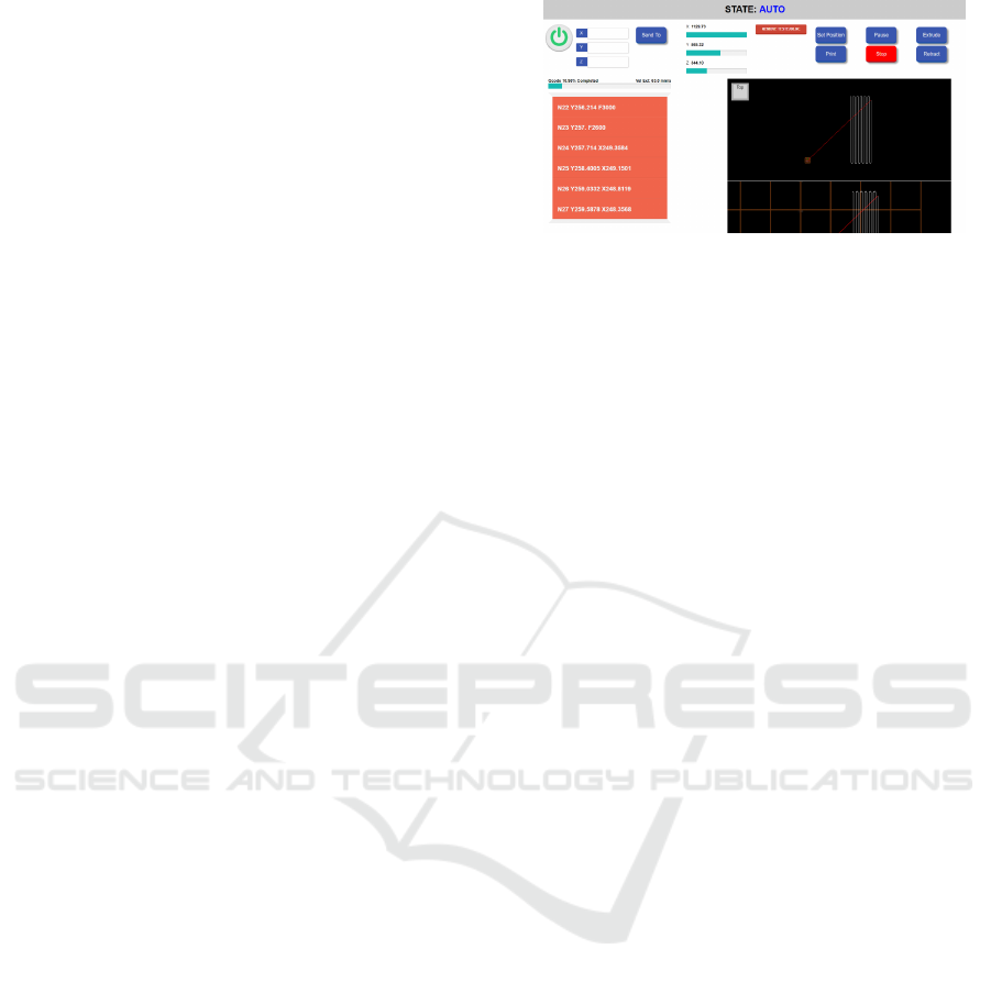
Figure 1: First Interface Prototype.
possible through an ADS (Automation Device Spec-
ification) interface that each module has and through
the ”ADS Router” in the software that manages and
can identify the recipients of the messages. This in
practice means that when a remote message arrives,
the ”ADS Router” can identify which module / device
this message is addressed to.
Finally, at the sensing/actuator layer there are sev-
eral different types of devices that can control and
monitor the physical process, such as servos, temper-
ature and pressure sensing devices, etc.
3.2 First Prototype
In order to validate the proposed architecture and
technologies, a first functional prototype was imple-
mented, although not in the final equipment, but in a
similar equipment in terms of functionality and char-
acteristics.
The developed prototype allowed to assess possi-
ble issues from the implementation and to validate the
architecture and the considered for the final system
in a real equipment, thus giving us unidealized infor-
mation of its behavior, forms of communication, and
integration issues. It also allowed us to show a first
approximation to the reality that would be put into
practice in the development of the final system. With-
out hard concerns about usability or requirements re-
sponding to user needs, the main focus of the proto-
type was to develop a system using a set of selected
technologies, as well as to analyze its behavior.
This prototype has a set of functions that allow to
control and monitor the process equipment and pa-
rameters (see Figure 1), such as monitoring the state
of the machine (it can vary between on / off, pause,
auto or manual), set the axes to a certain position,
send a GCode program to the machine to interpret and
execute, pause the equipment, abort the execution of a
GCode program, view the GCode lines that are being
executed in real time, track position and view the 2D
and 3D models drawings (Figure 2).
As conclusion, we confirmed that the set of se-
lected technologies was suitable for the development
I-AM: Interface for Additive Manufacturing
647

Figure 2: 2D and 3D views of the part being manufactured.
and was used as a reference in the development of the
final system.
4 DESIGN OF THE FINAL HMI
4.1 Requirements Elicitation
Requirements elicitation is a crucial phase in the life
cycle of each project because an erroneous, incom-
plete or non-existent requirement usually means seri-
ous design problems.
The main objectives of the requirements analysis
can be summarized in understanding the problem and
identifying the needs of the project and, as a result of
the analysis, the definition of a set of requirements
as specifications to be implemented, describing the
behaviors, properties and the expected attributes that
reflect the needs of stakeholders in the project (Fer-
reira, 2010, p.25). A survey of requirements was car-
ried out with a group of HMI users (see Table 1) that
were categorized into three large groups, ”Informa-
tive”, ”Functional”, and ” Complementary”.
4.2 Interface Prototype
The next step was to develop a first version of the
HMI. The strategy was to develop a mockup that man-
ifest the list of requirements collected from users.
The development of mockups facilitates the un-
derstanding of the requirements between all the par-
ties involved, presenting concepts and functionali-
ties of the software. There are several approaches
to develop mockups, that is, they may be low fi-
delity, with no screen interaction, but they allow for
quick adjustments or changes depending on feedback
collected, as well as complex and interactive mock-
ups that more closely represent the software to be
Table 1: Requirements from the operators.
Function Details Category
View Axis
Axis X
Axis Y
Axis Z
Axis B
Axis C
Informative
View Speeds
Operation
Polymer Extrusion
Fiber Extrusion
Informative
View Temperatures
(current / target)
Chamber
Chiller
Table / Platform
Extruder
Motors
Informative
Control Heating System
(set / on / off)
Chamber
Table / Platform
Extruder
Functional
Control Ventilation
(set / on / off)
Chamber
Table / Platform
Extruder
Functional
Set Operation Mode
Automatic
Manual
MDI mode
Functional
GCode Program Execution
Import
Start
Pause
Stop
General Homing
Axis Homing
Functional
GCode Manual Commands
Execute Command
Pause
Stop
Functional
Set Configuration Parameters
Operation Speed
Polymer Extrusion
Fiber Extrusion
Functional
History View Log Informative
Manual Control
(On / Off)
Global
Heating
Ventilation
Motors
Functional
Illumination
(On / Off)
Chamber Complementary
developed , but whose counterpart is the fact that
the necessary changes or adjustments are more time-
consuming to make.
The approach followed was to, in the first phase,
create mockups that visually had a representation as
close as possible to the final HMI, but which were
static. A web tool specializing in the creation of static
mockups was used (https://moqups.com/).
The design of the first mockups was intended to
conduct an observation and analysis on how the in-
formation would be organized and made available to
the users in the interface, as well as all to check the
fullness of the functionality available to the user. To
this end, it was a crucial to discuss with the potential
users of the interface operators of the AM equipment
in order to understand the priorities in the organiza-
tion of information and functionalities.
From that discussion, it resulted the first drawing
of the mockup illustrated in Figure 3, where it can be
observed that in the upper area of the screen there are
three groups of information that is being updated in
real time, relative to the position of the axes, the op-
erating speeds and temperatures measured at several
places.
ICINCO 2019 - 16th International Conference on Informatics in Control, Automation and Robotics
648

Figure 3: First static HMI prototype.
This was indicated as the most critical informa-
tion set and consequently should be placed to enable
a quick understanding for the user. Below there are
user interaction zones, namely the Automatic, Man-
ual and MDI modes.
In the Automatic mode it is allowed to execute and
control the execution of a G code file, in Manual mode
it is allowed to control and operate each axis manually
and individually and in the MDI mode it is allowed to
execute a G code command.
Finally, in the lower part of the screen it can be
seen a set of tabs that allow to control some parame-
ters related to the additive manufacturing process and
also to the equipment itself. The first tab: Heating, al-
lows you to control parameters related to the heating
system of the equipment, such as heating the cham-
ber, the platform (tray) or the extruder, as well as sim-
ply making variations in the temperatures of the same.
The Ventilation tab allows you to control the air sup-
ply of the camera. The Parameters tab allows you to
adjust the feed speeds, polymer extrusion and fiber
extrusion. The Other tab allows you to run a table ad-
justment function and control camera lighting. The
last tab allows you to turn off equipment components
such as motors, the heating system, the chamber heat-
ing and all equipment.
After the creation of the first static version of the
models, a second version was created. This version
allowed interactivity, that is, it was possible to navi-
gate between screens and tabs of the HMI, in order to
simulate the execution of all the tasks. Also note that
these respected the size of the touch screen that will be
used in the actual additive manufacturing equipment
and were created using a web tool (https://proto.io/)
that allowed exporting a prototype in HTML, making
it possible the execution of the same in the browser
Figure 4: HMI - Fully Interactive Mockup.
and the consequent navigation between screens. An
example of this model can be seen in Figure 4.
4.3 Interface Assessment
Since the interface is the most visible part of the
whole system and enables the interaction between op-
erators and the additive manufacturing equipment, it
has become fundamental to carry out an evaluation of
the interface as well as its usability.
Usability tests are processes that aim to evaluate
the ease of use of a product (system, interface, etc.),
preferably with the participation of groups of poten-
tial users, allowing to improve and bring constructive
criticism about its usability. In an ideal scenario, the
test participants will be real users and will perform
real tasks, creating a scenario very similar to the re-
ality that the product will be subject to when it is
launched. The test results will be obtained from the
observation and measurement of the interaction be-
tween the participants and the interface (Afonso et al.,
2013).
In order to perform the usability tests, two strate-
gies were used to evaluate the system, together with
a group of four users and the functional model exe-
cuted on the device’s touch screen. Considering that
the solution to be developed would be for a specific
equipment, that is, oriented to Additive Manufactur-
ing, it became more difficult to select users with suffi-
cient knowledge to perform usability tests. However,
according to several studies ((Virzi, 1992), (Sauro,
2010), (Nielsen, 2000) and (Molich, 2010)) a group
of four to five users may be sufficient to obtain value
results and cover approximately 80-90% of existing
usability problems.
The first evaluation strategy was based on the Sys-
tem Usability Scale (SUS) (Brooke, 1996) survey,
which allows us to measure the usability of a sys-
tem through a set of ten questions, and where re-
sponses are recorded on a Likert scale and should
ranging from 1 (Strongly Disagree) to 5 (Strongly
Agree) (Brooke, 1995). This tool allows to evalu-
ate a wide range of products or services and has the
I-AM: Interface for Additive Manufacturing
649

Table 2: SUS Survey Results.
Item User 1 User 2 User 3 User 4
I think that I would like to use this system frequently 4 4 4 5
I found the system unnecessarily complex 1 1 1 1
I thought the system was easy to use 5 4 5 4
I think that I would need the support of a technical person to be
able to use this system
3 2 2 2
I found the various functions in this system were well integrated 5 3 4 4
I thought there was too much inconsistency in this system 1 1 1 1
I would imagine that most people would learn to use this system
very quickly
5 4 5 4
I found the system very cumbersome to use 1 1 1 1
I felt very confident using the system 5 5 4 5
I needed to learn a lot of things before I could get going with this
system
2 1 1 1
SUS Score = 88,125
Figure 5: Home Screen of the Final HMI Design.
main advantages of being able to easily differentiate
between usable and non-usable systems, to be quite
easy to apply and to compare since it is widely used
(Brooke, 2013).
In the table 2 the results of the SUS are made
available, per question and per operator, and a calcu-
lation method specific to the tool is used to calculate
the ”SUS Score” per user. used the arithmetic mean
of all calculated ”SUS Score”. The final result was
88,125 in a maximum of 100, which indicates a high
degree of user satisfaction about the usability of the
system.
Notice that, complimentary to the SUS survey, we
have used observation instruments and open question-
naires that allowed us to gather additional information
about specific issues that operators pointed out that
could be improved or corrected in subsequent itera-
tions of the HMI design.
4.4 Final Design
The developed system is made available to the user
through a web interface, which is executable through
a browser. In addition to this layer of graphical inter-
face, the system also has a backend layer developed
using NodeJS technology and a document database,
RethinkDB, which in turn are connected to the Twin-
cat automation solution . Thus, the initial screen made
available to the user is that of Figure 5.
As it can be seen, the interface can be divided
into three main groups of use. The upper group con-
tains process control information, that is, it allows the
user to monitor in real time the position of the axes,
Figure 6: Working version of the I-AM HMI.
speeds and temperatures. The position of the axes is
made available in millimeters and is accompanied by
a graphic object representing the axis. In the case of
X, Y and Z axes, the graphic object is a progress bar
for each. The B axis, which in the actual equipment
corresponds to the inclination of the tray where the
printing takes place, is represented by a fixed gray
horizontal bar and a blue (dynamic) bar that demon-
strates the inclination of the table (as if the tray were
seen in profile ), corresponding to a certain angle in
degrees celsius. Finally, axis C, which in real equip-
ment corresponds to the rotation of the tray on itself,
is represented by a circumference and a red dot with
a blue line (dynamic) from the center of the circum-
ference for viewing the rotation angle (as if the board
was viewed from above). The system is also log a set
of parameters and displays them in the form of time
series. The working version of the developed HMI
alongside the 3D printer used in this work is depicted
in Figure 6
5 RESULTS
The developed system basically consists of a web in-
terface supported by a backend layer that, in turn, es-
tablishes and manages the communication with the
automation layer, and as such, it has become essen-
tial to close the cycle of this work to carry out tests
to the developed HMI which is connected to the final
additive manufacturing equipment.
These tests were possible to run with the group
of four users who participated in the interface val-
idation inquiries, however, since part printing has a
cost to the material that is used, only one part can be
printed. In the remaining tests the same procedure
was performed with the only difference that although
the axes of the equipment made the same movements,
the pieces were not printed and the remaining data
were simulated. This difference was explicit through
an attribute in the content of the G code and there-
fore, in the perspective of the HMI the functionality
ICINCO 2019 - 16th International Conference on Informatics in Control, Automation and Robotics
650

Figure 7: Sample part manufactured during the user tests.
would be exactly the same because it only guaranteed
the upload of the file selected by the user and gave the
order to the controller to begin its execution.
Since the equipment is not yet finished from an
automation point of view, some of its functionality is
not yet implemented.
After the tests were carried out, a new SUS survey
was made to the users in order to obtain new feed-
back about the usability of the HMI. The final result
was 89,375 in a maximum of 100, which indicates a
high degree of satisfaction in the usability of the sys-
tem. This value, compared to the value of the eval-
uations made to the models, was increased, since the
result had been 88,125. These results indicate that, in
general, users are satisfied with the developed HMI
and that it met their expectations. More relevant than
the quantitative assessment, the issues pointed out by
the operators were improved or corrected in the final
version of the HMI.
During the tests with the equipment que HMI was
used to control the manufacturing of sample pieces as
the illustrated in Figure 7
6 CONCLUSIONS
The work carried out allowed to verify that, although
there are already some approaches similar to the pro-
posal presented here, there is still a great margin of
evolution in order to take advantage of all the exist-
ing potential in the technological areas and direct it
to areas of applicability in the industry, especially if
consider the area of Additive Manufacturing.
The methodology used involved users throughout
the process. In a first phase, requirements were cre-
ated that allowed the creation of visual mockups and
obtaining first user feedback through surveys, includ-
ing usability studies, which in turn validated the pro-
posed solution and ensured in advance that necessary
adjustments were recorded. Based on the results, the
final solution was developed, and tests were carried
out on the actual equipment that resulted in the print-
ing of a part using the Additive Manufacturing as the
manufacturing process.
The development methodology of the interface,
centered on the operator needs, with validation and
evaluation by means of prototypes and user tests, re-
garding its usability, proved to be fundamental to
reach the aimed set of objectives. The final solution
proved to fit the users needs. The outcome of users
tests were a usability assessment close to the ”excel-
lent” according to the evaluation tool used (Bangor
et al., 2009). These results allowed us to validate the
usefulness and usability of the developed solution.
As future work, and in addition to the implemen-
tation of the features that are listed as requirements
but which have not yet been developed due to lack
of instrumentation or development in the project au-
tomation layer, the integration of an Augmented Re-
ality module with in order to visualize the part to be
printed in three dimensions and also to obtain infor-
mation on the process of printing it in real time, in
order to prove the feasibility and above all the con-
siderable value that this technology can contribute to
industrial processes.
An avenue to future developments is to general-
ize the proposed architecture towards a framework en-
abling the development of web based, cross-platform,
interactive and responsive interfaces for industrial
processes / appliances.
ACKNOWLEDGEMENTS
Parts of the presented work were supported by
project POCI-01-0145-FEDER-016414, co-funded
by Programa Operacional Competitividade e
Internacionalizac¸
˜
ao and Programa Operacional
Regional de Lisboa, by means of Fundo Europeu de
Desenvolvimento Regional (FEDER) and national
funds from FCT – Fundac¸
˜
ao para a Ci
ˆ
encia e Tec-
nologia. Parts of the presented work were conducted
under the scope of project Maintenance 4.0 - FEDER
02/SAICT/2016 23725.
REFERENCES
Afonso, A. P., Lima, J. R., and Cota, M. P. (2013). Usability
assessment of web interfaces: User testing. In 2013
8th Iberian Conference on Information Systems and
Technologies (CISTI), pages 1–7.
Bangor, A., Kortum, P., and Miller, J. (2009). Determining
what individual sus scores mean: Adding an adjective
rating scale. J. Usability Studies, 4(3):114–123.
Bermudez-Ortega, J., Besada-Portas, E., Orozco, J. A. L.,
Chacon, J., and de la Cruz, J. M. (2016). Develop-
I-AM: Interface for Additive Manufacturing
651

ing web & twincat plc-based remote control labora-
tories for modern web-browsers or mobile devices.
In 2016 IEEE Conference on Control Applications,
CCA 2016, Buenos Aires, Argentina, September 19-
22, 2016, pages 810–815.
Brooke, J. (1996). Usability evaluation in industry, chapter
”SUS-A quick and dirty usability scale.”. Taylor and
Francis. ISBN: 9780748404605.
Brooke, J. (2013). Sus: A retrospective. J. Usability Stud-
ies, 8(2):29–40.
Errington, J., DeMaere, T., and Wade, E. (2005). Support-
ing key console operator interactions through the con-
trol system interface. In 17th Annual Ethylene Pro-
ducers’ Conference, Atlanta GA.
Hollifield, B., Oliver, D., Nimmo, I., and Habibi, E. (2008).
The high performance HMI handbook: a compre-
hensive guide to designing, implementing and main-
taining effective HMIs for industrial plant operations.
Plant Automation Services, Houston, TX.
Ka
ˇ
cur, J., Durd
´
an, M., and Laciak, M. (2013). Utilization
of the plc as a web server for remote monitoring of the
technological process. In Proceedings of the 14th In-
ternational Carpathian Control Conference (ICCC),
pages 144–149.
Li, H. and Zhang, J. (2011). Study on remote plc experiment
system based on web. In 2011 Second International
Conference on Mechanic Automation and Control En-
gineering, pages 1683–1686.
Markforged (2018). Eiger. https://markforged.com/eiger/.
Molich, R. (2010). A critique of ”how to specify the partic-
ipant group size for usability studies: A practitioner’s
guide” by macefield. J. Usability Studies, 5(3):124–
128.
Nielsen, J. (2000). Why you only need to test with
5 users. https://www.nngroup.com/articles/why-you-
only-need-to-test-with-5-users/.
Sauro, J. (2010). A brief history of the magic number
5 in usability testing. https://measuringu.com/five-
history/.
Virzi, R. (1992). Refining the test phase of usability evalua-
tion: How many subjects is enough? Human Factors,
4(4):457–468.
ICINCO 2019 - 16th International Conference on Informatics in Control, Automation and Robotics
652
