
Robust Calibration Procedure of a Manipulator and a 2D Laser Scanner
using a 1D Calibration Target
Jan Alberts, Sebastian P. Kleinschmidt and Bernardo Wagner
Real-Time Systems Group, Institute for Systems Engineering,
Leibniz Universit
¨
at Hannover, Appelstraße 9A, D-30167, Hannover, Germany
Keywords:
Mobile Robotics, Extrinsic Calibration, Mobile Manipulation, 2D Laser Scanner, LiDAR, Parameter Opti-
mization.
Abstract:
An accurate extrinsic calibration between a robots’ exteroceptive sensors and its manipulator is essential for
tasks such as mobile manipulation and tactile exploration. Especially for extrinsic calibration of a manipula-
tors’ end effector and 2D laser scanner, state-of-the-art approaches often require complex calibration targets or
sensors which need to be mounted to the end effector. Therefore, such approaches are only suitable to a limited
extent for use in mobile robotics. In this paper, we present a simple but effective approach to determine the
six degrees of freedom transformation between the end effector of a serial manipulator and the center of a 2D
laser scanner. In contrast to other approaches, our approach requires only a 1D target for calibration. Whereas
complex calibration geometries often require a tool change for calibration, our approach is also applicable
using practical objects like a drill mounted to the end effector. As a consequence, a tool change is not required
for recalibration for many applications anymore. To evaluate the performance of our approach, we perform
the calibration based on simulated as well as real data. We compare our results against the ground truth of a
physically closed transformation chain using the lidars’ CAD data.
1 INTRODUCTION
The scientific attention on autonomous mobile manip-
ulators has been growing over the past years as the
technology promises immense potential in the fields
of industrial robotics, logistics or search and rescue
scenarios. Especially the combination of perception
and manipulation is promising for a multitude of ap-
plications. The environment of a mobile robot can
be captured by a variety of different exteroceptive
sensors such as RGB, thermal (Zeise. and Wagner.,
2016)(Mehltretter et al., 2019) or hyperspectral cam-
eras (Kleinschmidt and Wagner, 2018), laser scanners
(Wulf and Wagner, 2003) as well as radar sensors
(Fritsche and Wagner, 2017). Laser scanners are of
particular relevance for mapping and localization be-
cause of their robustness and accuracy. In addition
to sensors for environmental perception, mobile plat-
forms are often equipped with various types of ma-
nipulators to interact with their environment. In order
to perceive the environment as well as to interact with
it autonomously, the perception of the environment
must be combined with the movement of the manipu-
lator. To put sensors and manipulators into a geomet-
ric context, they have to be intrinsically and extrin-
sically calibrated. Depending on the desired task as
well as the sensor technology used, the specified ac-
curacy and tolerances must be adhered to. Additional
requirements may relate to the simplicity and robust-
ness of the calibration procedure since the laboratory
or industrial settings vary depending on the environ-
mental conditions or the professionalism and training
of the operator.
This paper focuses on the calibration of a 2D laser
scanner and a manipulator. Especially for extrin-
sic calibration of a manipulators’ end effector and
2D laser scanner, state-of-the-art approaches often re-
quire complex calibration targets (Antone and Fried-
man, 2007) or additional sensors (McIvor, 1999)
which need to be mounted to the end effector. There-
fore, such approaches are only suitable to a limited
extent for use in mobile robotics. Whereas complex
calibration geometries often require a tool change
for calibration, our approach is also applicable using
more practical objects like a drill mounted to the end
effector (Gray et al., 2013). As a consequence, a tool
change is not required for recalibration for many ap-
plications anymore. A calibration is thus also possible
112
Alberts, J., Kleinschmidt, S. and Wagner, B.
Robust Calibration Procedure of a Manipulator and a 2D Laser Scanner using a 1D Calibration Target.
DOI: 10.5220/0007946701120119
In Proceedings of the 16th International Conference on Informatics in Control, Automation and Robotics (ICINCO 2019), pages 112-119
ISBN: 978-989-758-380-3
Copyright
c
2019 by SCITEPRESS – Science and Technology Publications, Lda. All rights reserved

while a robot is in use, which is a particular advantage
in the context of mobile robotics. We show that our
approach is robust and accurate as well as simple to
use. For this reason, we evaluate our approach based
on simulated and real experiments.
2 RELATED WORKS
Robot calibration procedures have been studied ex-
tensively over the past decades. Regarding mobile
manipulators there exist calibration procedures con-
cerning the intrinsic calibration of the manipulator as
in (Bennett et al., 1991) or (Wieghardt and Wagner,
2017) but also procedures for extrinsic calibration of
manipulator and exteroceptive sensors.
The transformation between a manipulator and a
laser scanner can be determined by ascertaining the
relation between the known movement of the manipu-
lator and the corresponding measurements of the laser
scanner. In principle two approaches are investigated
in the research community:
1st) An additional exteroceptive sensor is attached
to the manipulator. This additional sensor is cali-
brated to the laser scanner. The still missing transfor-
mation between the attached sensor and the manipu-
lator needs to be determined as well.
The calibration between a laser scanner and a
camera is examined in several works as (McIvor,
1999), (Mei and Rives, 2006), (Zhang and Pless,
2004). An advantage of these approaches is that cal-
ibration techniques of laser scanner and cameras are
well established in the research community. The ma-
jor drawback regarding mobile manipulators is, that
an additional sensor is needed and a further calibra-
tion between manipulator and camera is neccessary.
This problem is known as hand-eye-calibration prob-
lem and is investigated in several works as (Tsai and
Lenz, 1989) or (Horaud and Dornaika, 1995).
2nd) A calibration target that is well known in its
geometry is attached to the manipulator and moved
within the laser plane. The calibration between the
laser scanner and the manipulator can be determined
by taking into account the known geometry of the cal-
ibration target, the movement of the manipulator and
the measurements of the laser scanner.
An advantage is that no additional sensor is
needed for calibration. The drawback of this calibra-
tion principle is that the laser scanner measurements
needs to be matched with the calibration target’s ge-
ometry unambiguously which requires a calibration
target of appropriate geometry and size.
(Pradeep et al., 2010) examine an approach, us-
ing the intensity of the moving end effector in a 3D
laser scan. This approach requires a 3D laser scanner
which is capable of measuring intensities. In (Antone
and Friedman, 2007) a 3D calibration target is used
to determine the needed transformation with a single
measurement of a 2D laser scanner. This method uses
complex calibration targets of different sizes depend-
ing on the desired accuracy of the calibration. (Ander-
sen et al., 2014) present a method that uses a 2D cali-
bration target. The calibration target is moved within
the spanned area of the 2D laser scanner and the trans-
formation is determined. This method has been eval-
uated in simulation.
In this paper, we propose a calibration procedure
that determines the transformation between a manipu-
lators base and a two 2D laser scanner. Therefore, we
move a 1D geometry within the spanned plane of the
2D laser scanner. In contrast to state-of-the-art cali-
bration procedures this paper examines a method that
does not require additional sensors, using a calibra-
tion target which has a much simpler geometry com-
pared to existing approaches. Furthermore, because
of the 1D nature of the object, alternative objects as
drills can also be used for calibration which makes
our approach independent of specialized calibration
bodies which are needed for other approaches.
The suggested approach simplifies the idea intro-
duced in (Andersen et al., 2014) by using a less com-
plex 1D calibration target. Whereas the approach pre-
sented in (Andersen et al., 2014) fits multiple features
of the calibration targets’ geometry simultaneously,
our proposed approach only fits one intersection of
the 1D calibration target with the laser plane at a time.
The lower number of features for an individual mea-
surement is compensated by repeated measurements
of the targets’ intersection for several configurations
of the manipulator. Besides, in contrast to (Ander-
sen et al., 2014), measurements of real experiments
are used for evaluation to show the capabilities of our
approach.
The calibration procedure does not require labora-
tory environment conditions and can be carried out by
operators without professional skills. The error of the
proposed calibration is lower than the tolerance of the
deployed laser scanner emphasizing its practical rele-
vance. As only a 1D calibration target is required the
procedure is applicable using drilling tools already at-
tached to the end effector.
In summarise the main contributions of this work
are:
• Calibration procedure using a 1D calibration tar-
get and no additional sensor
• Applicable without calibration target when used
with attached drilling tools
Robust Calibration Procedure of a Manipulator and a 2D Laser Scanner using a 1D Calibration Target
113
• Practical relevance due to the low error of calibra-
tion
• Simple and robust procedure in terms of applica-
bility and environmental conditions
The rest of this paper is organized as follows: In
Chapter 3 the problem formulation is provided con-
taining the mathematical fundamentals, the system
modeling such as the methodology of the proposed
approach. In Chapter 4 the experimental evaluation
is presented. The Methodology of the experimental
setup and evaluation is described and the results of
simulated and real experiments are introduced. The
conclusion is summarised in Chapter 5.
3 PROBLEM FORMULATION
In this Chapter the calibration of a manipulator with a
static 2D laser scanner is presented. We start by intro-
ducing the mathematical background and formulating
the system model of the manipulator kinematics and
the laser measurements. The missing transformation
and the calibration target will be introduced into the
model heading to our proposed method. Finally we
formulate an optimization problem leading to an op-
timal solution of the transformation between the laser
scanner and the manipulator.
3.1 Background
In 3D space a rigid body transformation from frame
F
a
to F
b
can be expressed by the homogenous trans-
formation H
b
a
∈ R
4x4
which is a non minimal rep-
resentation of the transformation
T
b:a
τ
∈ R
3
→ R
3
,
where τ =
ϕ,ϑ,ψ,t
x
,t
y
,t
z
is the 6D vector describ-
ing the transformation. The components ϕ, ϑ,ψ ∈
[0,2π[ represent the sequential ZYX-Euler angle rota-
tions while t
x
,t
y
,t
z
∈ R represent the translation along
the indicated axes.
The homogenous transformation matrix H (τ)
representing the transformation τ is given by:
H (τ) =
c
ϕ
c
ϑ
c
ψ
− s
ϕ
s
ψ
−c
ϕ
c
ϑ
c
ψ
− s
ϕ
s
ψ
c
ϕ
s
ϑ
t
x
s
ϕ
c
ϑ
c
ψ
+ c
ϕ
s
ψ
−s
ϕ
c
ϑ
s
ψ
+ c
ϕ
c
ψ
s
ϕ
s
ϑ
t
y
−s
ϑ
c
ψ
s
ϑ
s
ψ
c
ϑ
t
z
0 0 0 1
By convention c
i
and s
i
substitute cos(i) and sin(i).
Kinematics of serial chains may be mod-
eled as sequential homogenous transformations be-
tween the coordinate frames of the according links
H
c
a
= H
b
a
· H
c
b
. A 3D point in coordinate Frame F
a
is denoted as the 4D vector
p
a
=
p
a
x
p
a
y
p
a
z
1
T
,
thus homogenous coordinate transformations are ap-
plicable. The manipulators configuration is defined as
c ∈ C, where C describes the set of all configurations
during a calibration procedure.
3.2 System Modelling
The calibration procedure aims to determine the static
transformation T
B:L
Ψ
from the 2D laser scanner frame
F
L
to the frame of the manipulators base F
B
, where
Ψ =
ϕ,ϑ, ψ,t
x
,t
y
,t
z
is the estimated 6D vector de-
scribing the transformation using the ’ZYZ’ Euler
convention. This transformation is expressed as the
homogenous transformation matrix H
B
L
(Ψ).
A single measurement of the 2D laser range finder
represented as a 4D vector, making it applicable with
the homogenous transformation, is given by
t
X
L
(i) =
t
x
L
(i)
t
y
L
(i) 0 1
T
, where i ∈ N|i ≤ N is index-
ing the measurements, t is indexing the time and N is
the amount of measurements contained in a full 360
degree laser scan. The measurement of a full 360 de-
gree laser scan at time t is defined as the merged set
L(t) :=
N
[
i=1
t
X
L
(i,t)
The kinematic of the serial manipulator is combined
as a transformation from the manipulators base frame
F
B
to the endeffectors frame F
E
described by the ho-
mogenous transformation H
E
B
. By convention the
end effectors Z-axes points towards grasping direc-
tion. The setting is illustrated in Figure 1.
x
y
z
F
L
x
y
z
F
B
x
y
z
F
E
Figure 1: Setting and frame diagram of manipulator, laser
scanner and end effector.
ICINCO 2019 - 16th International Conference on Informatics in Control, Automation and Robotics
114

The geometry of the proposed calibration target is
a cylinder with height h and diameter d. Using the
assumption that the number of laser measurements
N → ∞ and the cylinders diameter d → 0 the calibra-
tion target can be modeled as an 1D line in R
3
point-
ing in Z-direction. The calibration target can now be
described by the homogenous transformation
H
G
e
G
0
(λ) =
1 0 0 0
0 1 0 0
0 0 1 λ
0 0 0 1
,
where λ ∈ [0,h]. The calibration target is attached to
the end effector described by the homogenous trans-
formation H
G
E
.
As the calibration target intersects the 2D laser
plane a closed chain of transformations accures, il-
lustrated in Figure 2.
F
L
F
B
F
E
X
L
H
B
L
H
E
B
H
G
i
E
F
G
i
Figure 2: Illustration of setting, frame diagram and trans-
formation chain between laser scanner, end effector, cali-
bration target and laser-measurement.
Each configuration c of the manipulator leads to a
unique intersection point in laser plane and calibration
target, independent of time and measurement index.
Thus the closed transformation chain is formulated as
X
L
(c) = H
B
L
(Ψ) · H
E
B
· H
G
0
E
· H
G
i
G
0
(c,γ) ·
0
0
0
1
| {z }
X
B
(c,γ)
, (1)
where X
L
(c) is the subset of L describing the sin-
gle measurement of the intersection point between
laser plane and calibration tool for configuration c.
H
G
i
G
0
(γ(c)) with γ(c) ∈ R|0 ≤ γ(c) ≤ h defines the cor-
responding intersection point of the calibration target
along its Z-axes. Thus X
B
(c,λ) describes the inter-
section point of the calibration target and the laser
plane referred to the manipulator base frame F
B
. In
following Equation (1) is summarized as
X
L
(c) = H
B
L
(Ψ) · X
B
(c,γ) (2)
3.3 Formulation of Optimization
The main principle of the proposed calibration proce-
dure is to measure the intersection point of the cali-
bration target within the laser plane for various con-
figurations of the manipulator. The closed transfor-
mation chain as expressed in Equation 2 is used to
define an error depending on the missing transfor-
mation H
B
L
(Ψ). By formulation of an optimization
problem the missing transformation can now be de-
termined optimal in terms of mean error.
As (2) describes the closed transformation chain
and relates the missing transformation to the manipu-
lator configuration and the laser measurement, an er-
ror is defined by
E =
e
x
e
y
e
z
0
T
leading to
E(c,Ψ,γ) = H
B
L
(Ψ) · X
B
(c,γ) −X
L
(c) (3)
Note that γ(c), describing the intersection between
calibation target and laser plane, is an unknown vari-
able, which may vary for each configuration. A scalar
error describing the mean translational abbreviation
between laser measurement and corresponding cali-
bration target intersection point using transformation
Ψ is given by:
E(c,Ψ,γ) =
r
∑
c∈C
E
T
· E. (4)
Finally the free optimization problem is formulated as
minimize
Ψ,γ(c)
E(c,Ψ,γ)
. (5)
Note that the solution of this optimization problem
provides the parameters Ψ of the missing transforma-
tion between laser scanner and manipulater base such
as γ(c) describing the intersection points of the cali-
bration target within the spanned laser plane for each
configuration.
4 EXPERIMENTAL VALIDATION
To validate our proposed calibration procedure sim-
ulational and real experiments are performed. The
simulation is used to demonstrate the feasibility of the
approach under ideal conditions. The real experiment
is used to evaluate the accuracy of the approach using
real hardware and measurements.
4.1 Methodology
The proposed calibration procedure requires a cali-
bration trajectory providing sufficient data for the op-
timization problem defined in Equation (5). As each
configuration provides two independent equations
Robust Calibration Procedure of a Manipulator and a 2D Laser Scanner using a 1D Calibration Target
115
and an additional unknown variable γ(c), six config-
urations are needed to determine the six parameters
of the transformation. Moreover the six end effector
configurations should provide distinctive parameters
concerning its translation in x-, y-, z-direction and ori-
entation about x- and y-angle in ZYX-Euler conven-
tion.
The optimization problem as stated in Equation
(5) is applied to the data of the simulation results and
the real measurements. The Matlab implementation
(fmincon) of a numerical interior point algorithm is
used as a solver. Lower and upper bounds are defined
such that
r
x,y,z
∈ −2 ≤ r
x,y,z
≤ 2
ϕ,ϑ, ψ ∈ −2π ≤ ϕ,ϑ,ψ ≤ 2π
The optimizer is initialised with the following param-
eters:
Ψ =
0,0, 0,0, 0,0
Several metrics will be used to determine the ac-
curacy of the calibration procedure. The translational
part of the transformation is evaluated using the trans-
lational abbreviation between ground truth
e
Ψ and es-
timated transformation
ˆ
Ψ. The rotational part is eval-
uated using abbreviations of ZYX-Euler angles. Both
evaluations are done for the single axes such as for the
associated 2-Norms:
e
x,y,z
=
e
x
e
y
e
z
=
e
t
x
−
ˆ
t
x
e
t
y
−
ˆ
t
y
e
t
z
−
ˆ
t
z
, e
|xyz|
= |e
x,y,z
|
2
e
ϕ,ϑ,ψ
=
e
ϕ
e
ϑ
e
ψ
=
e
t
ϕ
−
ˆ
t
ϕ
e
t
ϑ
−
ˆ
t
ϑ
e
t
ψ
−
ˆ
t
ψ
, e
|ϕϑψ|
= |e
ϕ,ϑ,ψ
|
2
The simulations are evaluated statistically, such
the standard deviation σ and expected value µ of the
metrics are provided.
µ
i
= E(|e
i
|)
σ
i
= σ(|e
i
|)
4.2 Simulations
The calibration procedure as described in Chapter 3
is first validated in simulation. The aim of this eval-
uation is to validate the feasibility of the procedure
and to determine statistically the accuracy of the pro-
vided transformation. For this purpose a transforma-
tion from laser frame to manipulator-base frame is de-
fined and an end effector trajectory is generated for
calibration. This calibration trajectory is a circular arc
in x and y plane while the height and orientation was
varied. In order to ensure sufficient end effector poses
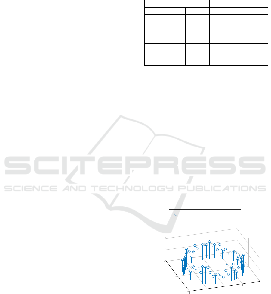
Table 1: Results of simulated experiment. Circular trajecto-
ries in manipulator xy-plane. Statistical evaluation of trans-
lational and rotational error.
Translational error Rotational error
µ(e
x
)/mm 3.338 µ(e
rot
x
)/
◦
0.494
µ(e
y
)/mm 3.110 µ(e
rot
y
)/
◦
0.470
µ(e
z
)/mm 7.169 µ(e
rot
z
)/
◦
0.192
µ(|e
x,y,z
|)/mm 9.581 µ(|e
rot
zyx
|)/
◦
0.800
σ(e
x
)/µm 6.736 σ(e
rot
x
)/
◦
0.147
σ(e
y
)/µm 4.973 σ(e
rot
y
)/
◦
0.108
σ(e
z
)/µm 28.193 σ(e
rot
z
)/
◦
0.018
σ(|e
x,y,z
|)/µm 20.434 σ(|e
rot
zyx
|)/
◦
0.132
the related Euler angles are constrained, such that the
z-axes intersects the laser-plane in positive direction.
The intersections between the z-axes of the end
effector and the laser-plane are calculated and pro-
vide the measurements of the laser scanner. The
noise of the laser scanner measurements is mod-
elled as normal distributed using standard deviation
of σ
L
= 10 mm. The noise of the manipulator is also
modelled as normal distributed in x-,y-,z-direction
using σ
M
= 1 mm. The ground truth of simulation
is defined as
e
r
x
e
r
y
e
r
z
=
30 50 20
cm and
e
ϕ
e
ϑ
e
ψ
=
5 7 3
◦
.
The measurements have been performed with 75
measuring points along the trajectory. The radius of
the circular calibration trajectory is defined as 80 cm.
The maximal variation of the end effectors height is
20 cm and the center of the circle is in the center of the
manipulators coordinate frame. Figure 3 illustrates an
exemlary calibration trajectory. The results are given
−1
0
1
−1
−0.5
0
0.5
1
0
0.2
0.4
x
y
z
Manipulator Trajectory
Figure 3: Calibration trajectory of end effector used in sim-
ulational experiment.
in Table 1.
Table 1 shows that the mean of the absolute trans-
lational error is about 9.5 mm. Furthermore a closer
inspection reveals that the error along z-axis is twice
the error in x- or y- direction. The rotational error
ICINCO 2019 - 16th International Conference on Informatics in Control, Automation and Robotics
116
about x- and y- axis is about half a degree and twice
the error about z-axis. The evaluated norm of the rota-
tional error reveals an error of 0.8
◦
. The standard de-
viation of translational and rotational error show that
the evaluated abbreviation between ground truth and
estimated error is distributed dense about the mean
values. The norm of the mean translational error
9.5 mm is below the laser measurements standard de-
viation of 10 mm.
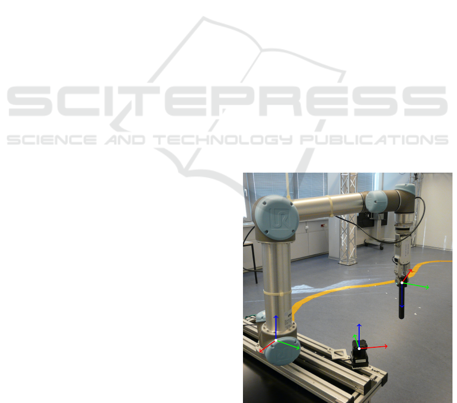
4.3 Real Experiments
The proposed method has also been evaluated in a
physical environment using real measurements of a
laser scanner and manipulator.
The deployed laser scanner is the Hokuyo model
UTM-30LX-EW and the manipulator that was used
for experimental evaluation is the Universal Robot
UR5. The technical details related to the accuracy
of the measurements are as follows: The repeatabil-
ity of the UR5 manipulator is ±0.1 mm. The accu-
racy of the Hokuyo UTM-30LX-EW laser scanner is
±30 mm
The ground truth of the real experiments has been
determined by generating a closed transformation
chain between manipulator and laser scanner frame
considering the provided CAD data of the laser scan-
ner.
The transformation from manipulator base to end-
effector is known. The laser scanner is assembled on
a self developed calibration mount. An Attachment
for the manipulator, that fits exactly into the mount,
is used, to constrain a known transformation between
end effector and laser scanner frame. The known
transformations from this serial chain deliver the un-
known transformation between manipulator base and
laser scanner.
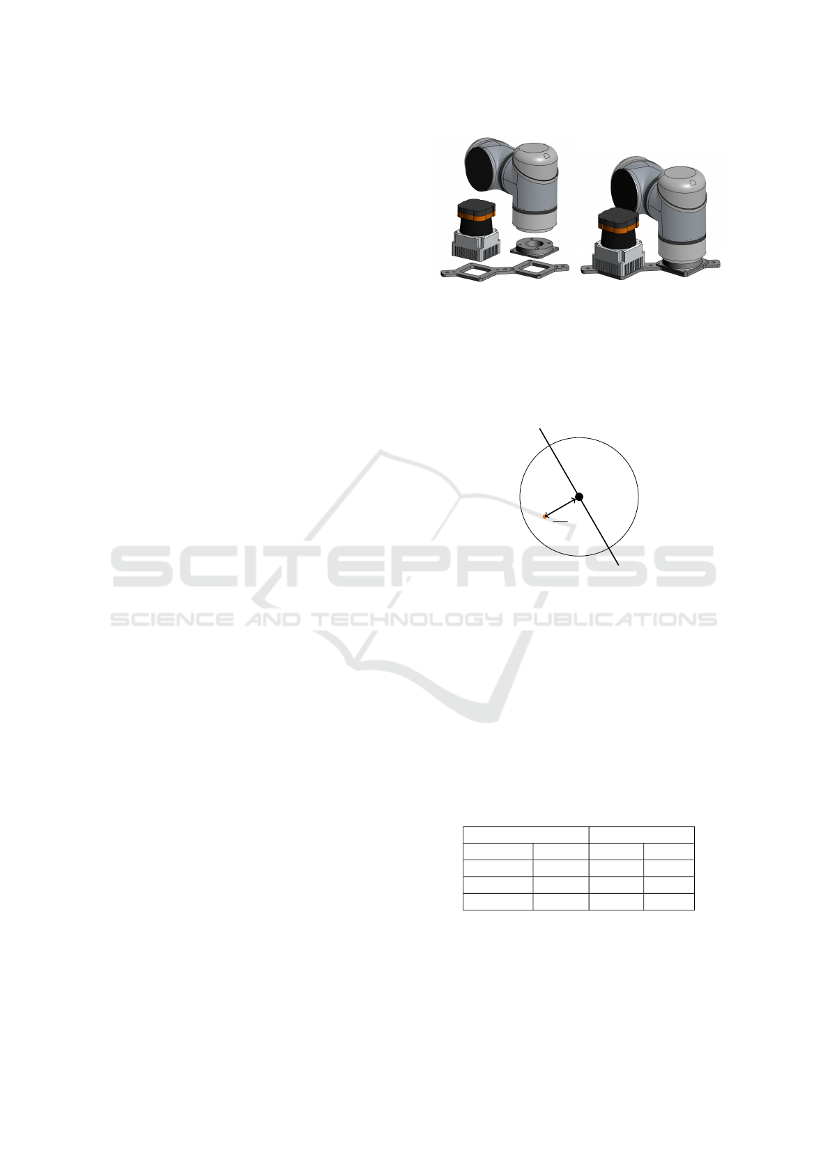
Figure 4 shows the developed calibration system.
The known technical dimensions of the laser scanner
and the developed sensor mount provide a transfor-
mation accuracy of ground truth in the range of man-
ufacturing tolerance which is ±0.2 mm for the used
3D-printer.
As the physical calibration target is a 3D body and
provides multiple scan points describing its intersec-
tion with the laser plane, the laser scan needs to be
processed before optimization in real experiments. As
the formulated model assumes a single intersection
point of a 1D line, the center of the intersecting cali-
bration tool is required.
The intersection of the cylinder shaped calibration
tool and the laser plane is assumed to be an ideal
circular arc. As the laser scanner only perceives a
semicircle, the center is determined by calculating the
(a) Disassembled calibration
system
(b) Assembled calibration
system
Figure 4: Calibration system providing ground truth. Laser-
scanner mount and manipulator attachment
arithmetic mean of the measurements and correcting
it about R · π/4. Figure 5 illustrates the correction of
the laser measurements.
R·π
4
Figure 5: Correction of laser measurements to determine
the center of the circular intersection. The orange dot marks
the arithmetic mean value of the semicircle. The black dot
marks the center of the circle.
The calibration trajectory is illustrated in Figure 6.
The manipulator moves the end effector in two semi-
circles with different radii and heights. The position
is held for 3 seconds in 20 degree intervals along
the semi-circles. The orientation of the end effector
was varied for each interval. Evaluations are given
in Table 2. The experimental setting is illustrated in
Figure 1.
Table 2: Results of real experiment. Circular trajectorie in
manipulator xy-plane. Evaluation of translational and rota-
tional error.
Translational error Rotational error
e
x
/mm 11.809 e
rot
x
/
◦
2.011
e
y
/mm 4.267 e
rot
y
/
◦
0.454
e
z
/mm 2.346 e
rot
z
/
◦
0.219
e
|xyz|
/mm 12.559 e
|rot|
/
◦
2.073
The absolute translational and rotational error is
about 12.6 mm and 2.1
◦
. A qualitative inspection re-
veals that the translational error in x-direction is al-
most three times the absolute error in y- and more than
five times the translational error in z-direction. The
Robust Calibration Procedure of a Manipulator and a 2D Laser Scanner using a 1D Calibration Target
117

−1
−0.5
0
0.5
1
−1
0
1
0
0.5
x
y
z
Manipulator Trajectory
Figure 6: Calibration trajectory of end effector used in real
experiment.
same relations occur for the rotational error. The rota-
tional error about the normal axis of the laser plane is
minimal while the rotational error around the X-axis
is maximal.
As the calibration trajectory for the real measure-
ments cannot cover the whole area of the laser scanner
because of the limited measuring range of 270
◦
, this
explains the relatively large error about the X-axis.
The data of the measurement cannot cover the whole
space and overweights the data in x-direction in opti-
mization.
However, the evaluated abbreviation between ground
truth and estimated translation has to be relativized,
as the used laser scanner provides an accuracy of
±30 mm. The provided calibration procedure ob-
tained a translational error which is less than a half
of this accuracy. Moreover the rotational error of
about 2.1
◦
is mostly influenced by the rotational er-
ror around the X-axis. As the laser measurements
only occur in x- and y-plane, this rotational error has
almost no effect on the measurements in x- and y-
direction. A rotational error around the X-axis of
2.1
◦
leads to a minimal translational error along the
X-axis as cos(2.1
◦
) = 0.9994. Under the assump-
tion that the laser measurements shall be used for ma-
nipulation the range of the manipulator shall not be
larger than 800 cm leading to a translational error of
0.48 mm.
5 CONCLUSIONS
In this paper we present a new calibration procedure
to determine the transformation between a manipula-
tors’ base and a 2D laser scanner. The proposed cali-
bration procedure does not require additional sensors
or complex calibration targets. Instead merely a sim-
ple 1D calibration target is required. The transforma-
tion is determined by solving an optimization prob-
lem that fits the missing transformation into the closed
transformation chain between manipulator pose and
laser measurement.
The approach has been evaluated by simulation
and physical experiments using a Universal Robot
UR5 manipulator and real laser measurements of a
Hokuyo UTM-30LX-EW laser scanner.
The results show that the accuracy of the calibra-
tion procedure is within the range of the laser scanners
accuracy. The simulational results as well as the re-
sults of the real experiments show variations between
the evaluated translational and rotational errors along
and around the several axis. While the pose of the end
effector provides 6D data, the measurements of the
laser scanner only reveal 2D data. Any kind of cali-
bration procedure has to resolve the problem of fitting
a 2D plane by projection from 6 dimesional space into
2D space. This fundamental type of problem may be
the reason why the rotational and translational error
about and around the several axis vary after optimiza-
tion.
Future research may focus on varying the calibra-
tion target. The radius of the physical calibration tar-
get may influence the calibration as the center of the
intersection may be determined more precisely. A
longer calibration target could also improve the cali-
bratin error as it enables a higher variation of feasible
trajectories. The influence of different trajectories is
also a point of interest for future research.
REFERENCES
Andersen, T. T., Andersen, N. A., and Ravn, O. (2014). Cal-
ibration between a laser range scanner and an indus-
trial robot manipulator. In 2014 IEEE Symposium on
Computational Intelligence in Control and Automa-
tion (CICA), pages 1–8.
Antone, M. E. and Friedman, Y. (2007). Fully automated
laser range calibration. In British Machine Vision
Conference (BMVC).
Bennett, D. J., Geiger, D., and Hollerbach, J. M. (1991).
Autonomous robot calibration for hand-eye coordina-
tion. The International Journal of Robotics Research,
10(5):550–559.
Fritsche, P. and Wagner, B. (2017). Modeling structure
and aerosol concentration with fused radar and li-
dar data in environments with changing visibility.
2017 IEEE/RSJ International Conference on Intelli-
gent Robots and Systems (IROS), pages 2685–2690.
Gray, T., Orf, D., and Adams, G. (2013). Mobile automated
robotic drilling , inspection , and fastening.
Horaud, R. and Dornaika, F. (1995). Hand-eye calibra-
ICINCO 2019 - 16th International Conference on Informatics in Control, Automation and Robotics
118

tion. The International Journal of Robotics Research,
14(3):195–210.
Kleinschmidt, S. P. and Wagner, B. (2018). Visual mul-
timodal odometry: Robust visual odometry in harsh
environments. In 2018 IEEE International Sympo-
sium on Safety, Security, and Rescue Robotics (SSRR),
pages 1–8.
McIvor, A. M. (1999). Calibration of a laser stripe pro-
filer. In Second International Conference on 3-D Dig-
ital Imaging and Modeling (Cat. No.PR00062), pages
92–98.
Mehltretter, M., Kleinschmidt, S. P., Wagner, B., and
Heipke, C. (2019). Multimodal dense stereo match-
ing. In Brox, T., Bruhn, A., and Fritz, M., editors,
Pattern Recognition, pages 407–421, Cham. Springer
International Publishing.
Mei, C. and Rives, P. (2006). Calibration between a central
catadioptric camera and a laser range finder for robotic
applications. In Proceedings 2006 IEEE International
Conference on Robotics and Automation, 2006. ICRA
2006., pages 532–537.
Pradeep, V., Konolige, K., and Berger, E. (2010). Calibrat-
ing a multi-arm multi-sensor robot: A bundle adjust-
ment approach. In International Symposium on Ex-
perimental Robotics (ISER), New Delhi, India.
Tsai, R. Y. and Lenz, R. K. (1989). A new technique for
fully autonomous and efficient 3d robotics hand/eye
calibration. IEEE Transactions on Robotics and Au-
tomation, 5(3):345–358.
Wieghardt, C. S. and Wagner, B. (2017). Self-calibration of
a mobile manipulator using structured light. In 2017
18th International Conference on Advanced Robotics
(ICAR), pages 197–203.
Wulf, O. and Wagner, B. (2003). Fast 3d scanning methods
for laser measurement systems. International Confer-
ence on Control Systems and Computer Science.
Zeise., B. and Wagner., B. (2016). Temperature correc-
tion and reflection removal in thermal images using
3d temperature mapping. In Proceedings of the 13th
International Conference on Informatics in Control,
Automation and Robotics - Volume 2: ICINCO,, pages
158–165. INSTICC, SciTePress.
Zhang, Q. and Pless, R. (2004). Extrinsic calibration of a
camera and laser range finder (improves camera cali-
bration). In 2004 IEEE/RSJ International Conference
on Intelligent Robots and Systems (IROS) (IEEE Cat.
No.04CH37566), volume 3, pages 2301–2306 vol.3.
Robust Calibration Procedure of a Manipulator and a 2D Laser Scanner using a 1D Calibration Target
119
