
Force Display Control System using 2 DOF Admittance Control in
Surgical Training Simulator with Chiseling Operation
Kentaro Masuyama
1
, Yoshiyuki Noda
2 a
, Yasumi Ito
2
, Yoshiyuki Kagiyama
2
and Koichiro Ueki
3
1
Integrated Graduate School of Medicine, Engineering and Agricultural Sciences, University of Yamanashi, Kofu,
Yamanashi, Japan
2
Faculty of Engineering Department, University of Yamanashi, Kofu, Yamanashi, Japan
3
Faculty of Medicine, University of Yamanashi, Chuo, Yamanashi, Japan
Keywords:
Surgical Training Simulator, Virtual Reality, Force Display Device, Chiseling, 2 DOF Admittance Control.
Abstract:
This study contributes to developing the virtual surgical training simulator for chiseling operation. In surgical
operations using the bone chisel, impact forces are applied to the bone by pounding the chisel with the mallet.
To virtually represent this situation in the training simulator, the force display system with high stiffness and
instant reaction to the impact force is needed. In order to realize this force display system, we constructed
the force display device with the ball-screw mechanism for obtaining the high stiffness, and proposed the
two degree-of-freedom (2 DOF) admittance control for reacting instantaneously in the previous study. In this
study, the force display control system using 2 DOF admittance control is analyzed, and the feedforward and
feedback controllers in 2 DOF admittance control are developed for improving the reaction of the force display
device. The efficacy of the proposed control system is verified by creating a virtual experience to the chiseling
manipulation of a hard object using the bone mallet. From the experimental results, it is confirmed that the
movement, contact, chiseling and splitting sensations are displayed more accurately than the conventional
approach.
1 INTRODUCTION
Surgical training simulators with force display have
been recently developed to allow surgeons to get into
their surgical skills. The simulated environment al-
lows vision, hearing and force sensory immersion so
that trainees can practice surgical procedures repeat-
edly and safely with high realistic sensation (Maier
et al., 2019), (Lam et al., 2013). In recent stud-
ies, devices with force display have used either the
parallel mechanism, which the end effector is con-
nected directly with three independent links (Hung
et al., 2018), or the serial link mechanism, which the
links are joined serially from the base to the end effec-
tor (Bugdadi et al., 2018). These devices with force
display make possible to exhibit the high degree-of-
freedom (DOF) of motion and high response, which
allows creating high realistic sensation for surgical
training with soft tissues.
However, in oral and orthopedic surgeries, large
forces are applied to the bone and tooth as hard tis-
sues by using the drill, saw and chisel. Previously
proposed force display devices can be broken by ap-
a
https://orcid.org/0000-0001-8500-5529
plying the necessary large impact forces used in the
surgeries to the hard tissues, and be limited to input
of small force (Yanping et al., 2014), (Wijewickrema
et al., 2018). Especially, virtualizing the situation that
the surgeon chisels the hard tissue by pounding with
the mallet requires the force display device with high
stiffness for withstanding the impact force and high
response for reacting instantaneously to the impact
force.
In the previous study by the present authors (Ma-
suyama et al., 2018), the force display device with
the ball-screw mechanism was constructed for hav-
ing high stiffness, and the 2 DOF admittance control
was proposed for reacting instantaneously to the im-
pact force. However, the feedforward and feedback
controllers in the 2 DOF admittance control for cre-
ating high realistic sensation have not been designed
reasonably in the previous study.
In this study, we propose the design of force dis-
play control system using the 2 DOF admittance con-
trol for creating high realistic sensation to the chisel
operation. The 2 DOF admittance control for force
display is analyzed theoretically. Then, the feedfor-
ward and the feedback controllers in the 2 DOF ad-
mittance control are designed in accordance with the
Masuyama, K., Noda, Y., Ito, Y., Kagiyama, Y. and Ueki, K.
Force Display Control System using 2 DOF Admittance Control in Surgical Training Simulator with Chiseling Operation.
DOI: 10.5220/0007950307670774
In Proceedings of the 16th International Conference on Informatics in Control, Automation and Robotics (ICINCO 2019), pages 767-774
ISBN: 978-989-758-380-3
Copyright
c
2019 by SCITEPRESS – Science and Technology Publications, Lda. All rights reserved
767

!"#$%&'(")$&
*"+,&-.//012%$*
34(#)"#5&
67$%.+"4#
8$%94:4+4%;
<$)(2+"4#&'$.%;
<4+.%=&>#24)$%
'%"7&4?&-4#$&&
@,"1$/
A0.B"1
C4%2$&8$#14%
<4+.+"4#./
D$2,.#"1:
!
"
x
y
z
!
#
Figure 1: Force Display Device for Surgical Training Sim-
ulator Using Bone Chisel.
analysis. The efficacy of the proposed force display
control system is verified by the experiments of vir-
tual chiseling operation using the force display with
high stiffness.
2 FORCE DISPLAY DEVICE
An illustration of the proposed force display device
for the virtual surgical simulator with chiseling the
hard tissue is shown in Fig. 1. This device has 5
DOF motion, which the chisel can move to x-, y-
and z-directions and rotate to ϕ
y
- and ϕ
z
-directions.
The translational motion of the force display device
is realized using a ball-screw mechanism to have the
high stiffness so that it withstands the impact force by
pounding the mallet. The mass of the moving object
on y-axis is 17[kg]. The maximum display force on
the translational motion is 100[N] and the maximum
display torque on the rotational motion is 7.5[Nm],
respectively. The maximum velocity on the transla-
tional motion is 0.76[m/s] and the maximum angu-
lar velocity on the rotational motion is 1181[deg/s],
respectively. The maximum transfer distance of the
chisel in each direction is 0.29[m]. Both maximum
rotational angles of the chisel in ϕ
y
- and ϕ
z
-directions
are same as 65[deg]. These specifications of the force
display device satisfy to create the realistic surgical
simulation using the chisel.
The 6-axis force sensor is installed at the base of
the chisel’s rotational mechanism. The impact or ma-
nipulation force added to the chisel can be measured
by the force sensor.
3 ANALYSIS OF FORCE DISPLAY
CONTROL SYSTEM
In the analysis of the force display control system, the
2 DOF admittance control is compared with a general
admittance control. The force display control system
is required that the motion of the drive system pre-
cisely reproduces the output from the virtual model.
Therefore, the transfer characteristics of both the gen-
eral and the 2 DOF admittance controls are discussed
as follows.
3.1 Admittance Control
The general admittance control installed to a single
axis is shown in Fig. 2, where F is the operational
force measured by the force sensor, F
v
is the modi-
fied operational force through the low-pass filter, u is
the input command, x
d
is the position of the tip of the
chisel, d is the disturbance, P
D
is the dynamics of the
drive system, P
V
is the virtual model that represents
the chiseling operation of the hard tissue by pound-
ing the chisel with the mallet, and L
F
is the low-pass
filter used for suppressing the sensor noise. Gener-
ally, this admittance control scheme has been used for
constructing the force display device.
It is necessary to analyze the responsiveness of the
admittance control as shown in Fig. 2. The system-
wide transfer function is represented as
X
d
(s) = P
D
(s)P
V
(s)L
F
(s)F(s) + P
D
(s)D(s), (1)
where s is a Laplace operator. Thus, the responsive-
ness of the force display device can be degraded by
the response lags of the drive system, P
D
, and the low-
pass filter, L
F
. Moreover, it is difficult to reproduce
precisely the response of the virtual model, when the
disturbances occur in the drive system.
!"#$%&'()*+,'
-*."$"*/
0#"1,(23.$,4
56,#&$"*/&'
7*#8,
9
:
;
<
=/6%$
!,'*8"$3
>
?
>
@
A*BC-&..(7"'$,#
D
E
F
9
G
0".$%#H&/8,
:
G
:I
G
Figure 2: Block Diagram of Admittance Control.
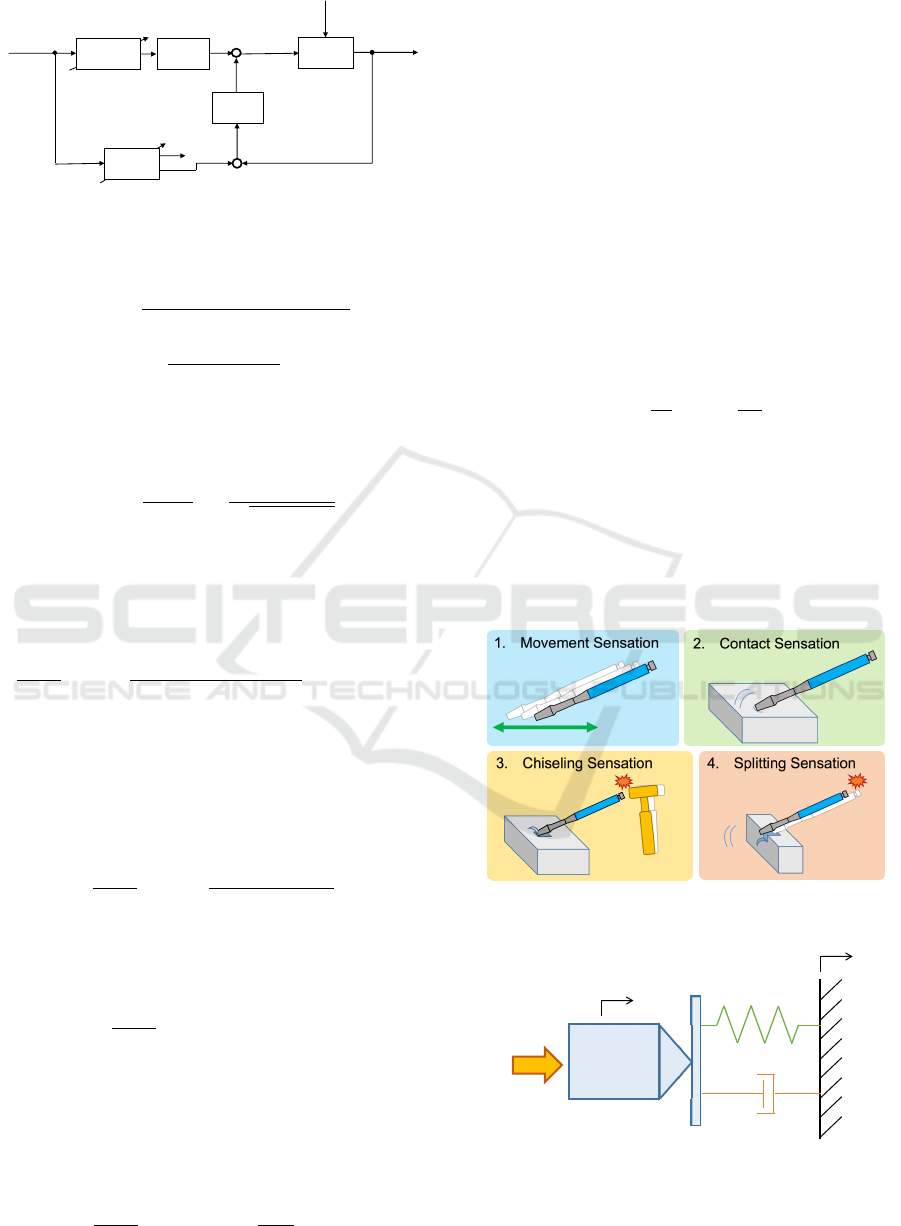
3.2 2 DOF Admittance Control
The block diagram of the 2 DOF admittance control
proposed by the present authors(Masuyama et al.,
2018) is shown in Fig. 3. The system-wide transfer
ICINCO 2019 - 16th International Conference on Informatics in Control, Automation and Robotics
768
!"
#
$%&'()*+,-./*
! "
0&%1/+234'/5
!
!
67/&)'%-8)*
9-&:/
;
!
<
=
=
>>
=
>?
!
<
@87('
$/*-:%'3
A
B
C
A
D
@81/&4/
0&%1/+234'/5
9E F-8'&-**/&
99+F-8'&-**/&
G
H
A
B
A
D
IJ
K
=
L
M-4%'%-8
0%4'(&N)8:/
O
!
#
Figure 3: Block Diagram of 2 DOF Admittance Control.
function can be represented as
X
d
(s) =
P
V
(s)(L
F
(s) + P
D
(s)C(s))
1 + P
D
(s)C(s)
F(s)
+
P
D
(s)
1 + P
D
(s)C(s)
D(s), (2)
where C is the feedback controller. The gain charac-
teristics of the low-pass filter in the frequency domain
is represented as
|L
F
(ω)| =
X
d
(ω)
F(ω)
=
1
q
ω
2
/ω
2
f
+ 1
, (3)
where ω is the angular frequency, and ω
f
is the cut-off
angular frequency. Therefore, the gain of the low-pass
filter in the low-frequency range converges as L
F
→1,
and the transfer function X
d
/F can be represented as
X
d
(s)
F(s)
ω→0
=
P
V
(s)(1 + P
D
(s)C(s))
1 + P
D
(s)C(s)
= P
V
(s). (4)
The dynamics of the drive system and the low-pass
filter can be ignored in the low-frequency range.
However, the gain of the low-pass filter in the
high-frequency range converges as L
F
→ 0. The gain
of the transfer function X
d
/F in the high-frequency
range can be represented as
X
d
(s)
F(s)
ω→∞
=
P
V
(s)P
D
(s)C(s)
1 + P
D
(s)C(s)
. (5)
Then, increasing the gain of the feedback controller as
P
D
(s)C(s)≫1 allows the responsiveness of the force
display device to be improved as
X
d
(s)
F(s)
P
D
(s)C(s)≫1
ω→∞
= P
V
(s). (6)
The ideal responsiveness in the high-frequency range
can be realized by the feedback controller with high
gain. Moreover, the disturbance can also be sup-
pressed by increasing the gain of the feedback con-
troller C(s) as
X
d
(s)
D(s)
P
D
(s)C(s)≫1
=
1
C(s)
≈ 0. (7)
Therefore, the responsiveness and disturbance sup-
pression of the control system in the force display de-
vice can be improved by the 2 DOF admittance con-
trol with high gain feedback controller as mentioned
above.
The mathematical representations of each block
are described in the following sections.
4 DRIVE SYSTEM MODEL: P
D
The servomotors are applied to the drive system on
each axis as shown in Fig. 1, and the velocity feed-
back control is implemented in each servomotor sys-
tem. Therefore, the drive system can be represented
as
¨x
d
(t) = −
1
T
m
˙x
d
(t) +
K
m
T
m
u(t), (8)
where T
m
is the time constant in seconds, and K
m
is the gain. The time constants and the gains
are identified as T
mx
=4.93[ms] and K
mx
=1.00 in x-
direction, T
my
=4.91[ms] and K
my
=1.00 in y-direction,
and T
mz
=5.76[ms] and K
mz
=1.00 in z-direction, re-
spectively.
!" #$%&'&()*+&(,-).$(
/" 0$()-1)*+&(,-).$(
2" 03.,&4.(5*+&(,-).$( 6" +74.)).(5*+&(,-).$(
Figure 4: Situations between Chisel and Hard Tissue.
Chisel
!
"
#$%&
'
"
#()*&
+
"
#$%),&
-#(&
.
"
#*&
/#*&
Figure 5: Dynamics of Virtual Model.
Force Display Control System using 2 DOF Admittance Control in Surgical Training Simulator with Chiseling Operation
769

!
"
"
!
"#
$
"
$
%
&
'()*+*(,-./(0*+1
2(3./4
'5657.+.6)4859
2(3./4
'5657.+.6)48:9
;
$
2(3*<*.3
=>.65+*(,5/4?(60.
@A*+0B*,C
D(,3*+*(,
!#
!
!
"
"
E
$
F
$
%
G
$
H,>I+4+(
J6*K.4@1)+.7
L
;
=>.65+*(,5/
?(60.
"
M
@I>>(6+.34=:N.0+
'()*+*(,
!
O0+I5/4'()*+*(,
%
&
@I>>(6+.3
=:N.0+
J1,57*0)
Figure 6: Block Diagram of Virtual Model.
5 VIRTUAL MODEL OF
CHISELING OPERATION: P
V
The virtual model is the source of the force repre-
sentation for creating the operating sensation of the
chisel, which is illustrated in Fig. 4. These situations
can be represented in the virtual model shown in Fig.
5. The dynamics of the virtual model is represented
as
m
v
¨x
v
(t) + c
v
( ˙x
v
(t) − ˙z(t)) + k
v
(x
v
(t) −z(t)) = F(t),
(9)
where x
v
is the position of the tip of chisel in the
virtual model and z is the position of the supported
object. The model parameters m
v
, k
v
, and c
v
are the
mass, spring constant and viscosity coefficient in the
virtual model represented as a spring-mass-damper
system, respectively. The hard contact sensation can
be created by the virtual model with high viscoelastic
characteristics. The chiseling sensation by pounding
with the mallet is created by the movement of the sup-
ported object.
5.1 Derivation of Parameters in Virtual
Model
The block diagram of the virtual model is shown in
Fig. 6. The model parameters m
v
, k
v
, and c
v
can be
varied in accordance with the situations. In the situa-
tion that the chisel is contacting to the hard tissue, the
model parameters can be derived by transforming the
virtual model of Eq. (9) to the generalized form as
¨x
v
+ 2ζω
n
˙x
v
+ ω
2
n
x
v
= 2ζω
n
˙z + ω
2
n
z + Kω
2
n
F, (10)
where
ω
n
=
s
k
v
m
v
, ζ =
c
v
2
√
m
v
k
v
, K =
1
k
v
. (11)
Table 1: Parameters of Virtual Model on Situations.
Situation
Model Parameters
m
v
[kg] c
v
[kg/s] k
v
[N/m]
(a)
Contacting
100
1.2×10
4
3.6×10
5
Hard Tissue
(b) Chisel in Air 2 20 0
Generalized Parameters
ω
n
[rad/s] ζ ω
c
[rad/s] K
(a) 60 1 -
2.8×10
−6
(b) - - 10
5.0 ×10
−2
ω
n
is the natural angular frequency, ζ is the damping
ratio and K is the gain of the virtual model. In the sit-
uation that the chisel is manipulated in the air, since
the spring element and the supported object are re-
moved from the virtual model, the virtual model can
be transformed to the first order-lag system with the
integrator as
¨x
v
+ ω
c
˙x
v
= Kω
c
F, (12)
where
ω
c
=
c
v
m
v
, K =
1
c
v
. (13)
ω
c
is the cut-off angular frequency. We adjust the
model parameters based on the generalized forms rep-
resented in Eqs. (10), (12).
The model parameters for each situation are
shown in Table 1. The damping ratio ζ in the situation
(a) is given as ζ=1 for suppressing the vibration. The
other parameters in the situation (a) can be obtained
experimentally such that they are increased until the
chisel stays against the operational force. On the other
hand, the parameters in the situation (b) can be ob-
tained such that they are decreased until the chisel can
be moved freely.
The contact sensation on the hard tissue is created
by switching the model parameters from (b) to (a).
The split sensation is created by switching the model
parameters from (a) to (b). The switching condition
of the model parameters is shown as
[ m
v
,c
v
,k
v
] =
Model Parameters (a),
( F
v
>0 ∧ z≤x
d
≤δ ∧ 0≤z≤δ ),
Model Parameters (b), ( else ),
(14)
where δ is the width of the hard tissue, F
v
is the
modified operational force through the low-pass fil-
ter, L
F
. In this study, the width of the hard object
is δ=10[mm], the supported object position is firstly
z=0[m].
ICINCO 2019 - 16th International Conference on Informatics in Control, Automation and Robotics
770

5.2 Movement of Supported Object
The movement of the supported object should be de-
signed based on the actual chiseling operation. The
relation between the pounding force with the mallet
and the travel distance of tip of the chisel can be mea-
sured in the actual chiseling operation. In this study,
the acrylic plate is used as the chiseled object for fa-
cilitating to obtain the hard tissue and be able to mea-
sure easily the travel distance of tip of the chisel. The
acrylic plate used in this experiment is shown in Fig.
7, and the chisel and the mallet are shown in Fig. 8.
The experimental environment of the actual chiseling
operation with the acrylic plate is illustrated as Fig.
9. To measure the pounding force with the mallet, the
acrylic plate and the force detector are clamped with
the vices. The chisel angle is fixed to 30[deg] by the
fixture placed under the chisel. The tip travel distance
of the chisel is exactly measured with the slide caliper.
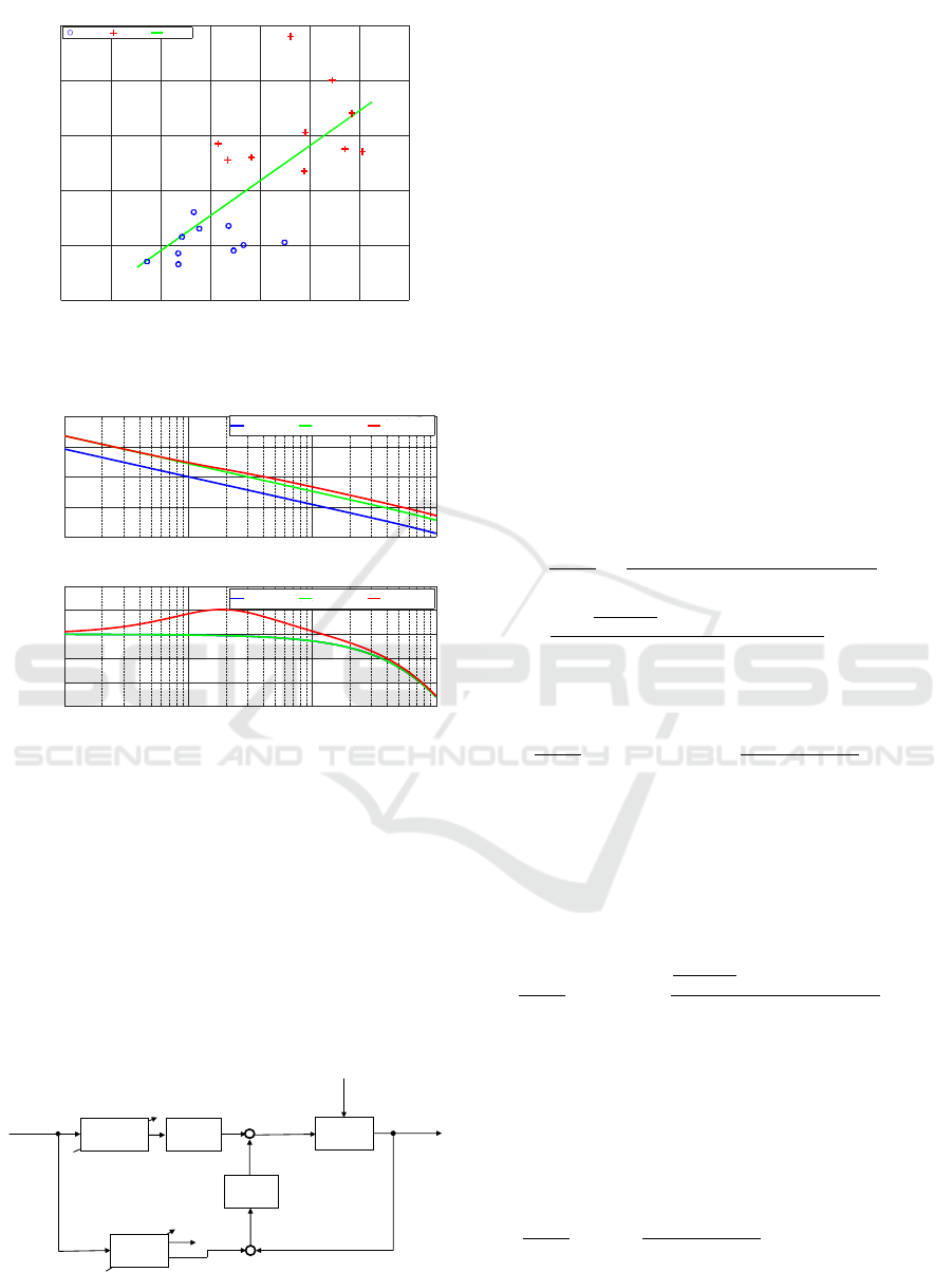
The experimental results of the relation between
the pounding forces and the tip travel distance of
the chisel are shown as Fig. 10. The circle and
the plus markers are shown as the tip travel dis-
tances caused by weak and strong pounding forces,
respectively. These relations are modeled by the least
squares method and represented as
∆z(F) = 6.38 ∗10
−5
F(t) −3.81 ∗10
−4
. (15)
The supported object position is shown as
z =
∑
∆z(F), (z≤x
d
∧ 0≤ z≤δ ∧ F ≥F
d
), (16)
where F
d
is the dead band of the pounding force with
mallet. In this study, the force dead band is F
d
=30[N].
6 LOW-PASS FILTER: L
F
The low-pass filter is applied in front of the virtual
model to reduce sensor noise and represented as
˙
F
v
= −ω
f
F
v
+ ω
f
F. (17)
The cut-off angular frequency used for the purposes
of this study is ω
f
=10[rad/s]. ω
f
can be determined
by the preliminary experiments. In the experiment,
ω
f
is increased until the vibrating motion is caused.
And, the largest frequency is selected in the condition
with suppressing the vibration.
!""
#
"
!""
Figure 7: Acrylic Plate.
!
"#$
%%$
&&#
Figure 8: Chisel and Mallet.
!"#$%&'
()*+%,-./01*23%
4562$/2&-75)3%
75)3%-8%205)-4,*1%
7/916)%
:/3%
;3)<,/3-4,*1%
=>/0%,
?*,,%1
75)3%-.%1%315)
Figure 9: Illustration of Actual Chiseling Operation with
Acrylic Plate.
7 DESIGN OF FEEDBACK
CONTROLLER: C
A phase lead compensator is applied to the feed-
back controller for increasing the gain in the high-
frequency range. The phase lead compensator can be
represented as
C(s) = k
1 + αT s
1 + T s
, (k, T > 0, α > 1), (18)
Force Display Control System using 2 DOF Admittance Control in Surgical Training Simulator with Chiseling Operation
771
Travel Distance[mm]
Force[N]
5
4
3
2
1
0
706050403020100
Weak Strong LSM
Figure 10: Experimental Results of Chiseling Operation
with Acrylic Plate.
Frequency[rad/s]
100
50
0
-50
-100
2
10
1
10
0
10
-1
10
Gain[dB]
(s)
D
(s) C(s)P
D
(s)
D
P kP
Frequency[rad/s]
-70
-80
-90
-100
-110
-120
2
10
1
10
0
10
-1
10
Phase[deg]
(s)
D
(s) C(s)P
D
(s)
D
P kP
Figure 11: Bode Diagram of Open Loop Systems
with/without Compensator.
where k is the gain, α and T are the control parameters
in this compensator. These parameters are designed
such that the controller gain in the high-frequency
range is risen, while the vibration is suppressed. In
this study, the gain is k=3, the parameters in the con-
troller are α=1.46 and T =0.42. The frequency char-
acteristics of this phase lead compensator is shown as
Fig. 11. The frequency band of the high-frequency
range can be improved by this phase lead compen-
sator.
!"
#
$%&'()*+,-./*
! "
0&%1/+234'/5
!
!
67/&)'%-8)*
9-&:/
;
!
<
=
=
>>
=
>?
!
<
@87('
$/*-:%'3
A
B
C
A
D
@81/&4/
0&%1/+234'/5
9E F-8'&-**/&
99+F-8'&-**/&
G
H
A
I
B
A
D
JK
L
=
M
N-4%'%-8
0%4'(&O)8:/
P
!
#
Figure 12: Block Diagram of 2 DOF Admittance Control.
8 DESIGN OF FEEDFORWARD
CONTROLLER: L
F
P
V
The feedforward controller consists of the low-pass
filter and the virtual model. The contact sensation
can be degraded by the difference of the responses
between the feedforward controller, L
F
P
V
, and the
proper virtual model, P
V
. Thus, the virtual model in
the feedforward controller is modified as L
F
˜
P
V
. The
modified virtual model
˜
P
V
can be derived as
m
v
¨x
v
(t) + c
v
( ˙x
v
(t) − ˙z(t)) = F
v
(t), (19)
By the modification of the virtual model in the feed-
forward controller,
˜
P
V
, the contact sensation in accor-
dance with the proper virtual model may not be rep-
resented precisely. Therefore, we analyze the 2 DOF
admittance control system with the modified virtual
model in the feedforward controller as below.
The system-wide transfer function of the 2 DOF
admittance control which is modified the virtual
model to Eq.(19) can be represented as
X
d
(s)
F(s)
=
˜
P
V
(s)L
F
(s) + P
V
(s)P
D
(s)C(s)
1 + P
D
(s)C(s)
=
(1 +
k
v
m
v
s
2
+c
v
s
)L
F
(s) + P
D
(s)C(s)
1 + P
D
(s)C(s)
P
V
(s). (20)
The gain of the low-pass filter in the high-frequency
range decreases as L
F
→0 and can be shown as
X
d
(s)
F(s)
P
D
(s)C(s)≫1
ω→∞
=
P
D
(s)C(s)
1 + P
D
(s)C(s)
P
V
(s) (21)
= P
V
(s).
Thus, the proper virtual model P
V
can be represented
in the high-frequency range.
However, the gain of the low-pass filter in the
low-frequency range converges as L
F
→1 and can be
shown as
X
d
(s)
F(s)
ω→0
=
k
v
m
v
s
2
+c
v
s
+ 1 + P
D
(s)C(s)
1 + P
D
(s)C(s)
P
V
(s).
(22)
Here, the operation in the low-frequency range is in
the movement sensation as shown in Fig. 4. The
virtual spring constant in the movement sensation is
k
v
=0[N/m] as shown in Table 1. Therefore, the gain
of the transfer function X
d
/F in low-frequency range
can be shown as
X
d
(s)
F(s)
ω→0
=
1
+
P
D
(
s
)
C
(
s
)
1 + P
D
(s)C(s)
P
V
(s) = P
V
(s). (23)
Thus, even if the virtual model is modified as Eq.(19),
the virtual model can be reproduced properly by the
proposed 2 DOF admittance control.
ICINCO 2019 - 16th International Conference on Informatics in Control, Automation and Robotics
772
(a)
(c)
(b)
(d)
(e)
(f)
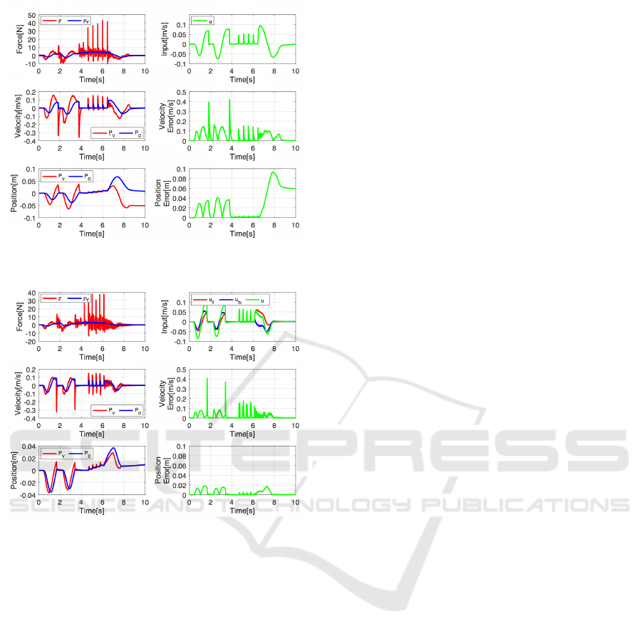
Figure 13: Experimental Results by Using Conventional
Admittance Control.
(a)
(c)
(b)
(d)
(e)
(f)
Figure 14: Experimental Results by Using 2 DOF Admit-
tance Control.
9 EXPERIMENTAL RESULTS
The efficacy of the proposed 2 DOF admittance con-
trol is verified by comparing with the conventional
admittance control. In order to confirm that the rep-
resentation of the proper virtual model can be created
precisely by the proposed approach, we evaluate the
error between the outputs of the proper virtual model
and the drive system.
The experimental results using the conventional
admittance control are shown in Fig. 13, where (a)
shows the operational force measured by the force
sensor, (b) is the input command to the drive system,
(c) and (e) are the velocity and the position of the tip
of chisel and, (d) and (f) are the absolute error of the
velocity and the position, respectively. We show only
the motion on the y-axis due to space limitations. We
also obtain similar results on the other axes. The edge
of the hard tissue is located at x
d
=0[mm]. The transla-
tional motion of the chisel is stopped at x
d
=0[mm], as
seen around 2[s] and 4[s]. As seen from these results,
the sensation caused by contacting the hard tissue can
be created. There are some impact forces arisen by
pounding the chisel with the mallet after 4[s]. The
tip of chisel is moved instantaneously with moving
the supported object. After the impulse of the im-
pact forces reached to the width of the hard object,
10[mm], the split sensation has created.
On the other hand, the experimental results us-
ing the 2 DOF admittance control are shown in Fig.
14. The graphs in Fig. 14 are same arrangement to
Fig. 13. The errors of the velocity and the position
in the movement, chiseling and splitting operation are
smaller using the proposed 2 DOF admittance control
than the conventional one. Therefore, the sensation to
operate the chisel is created precisely by implement-
ing the proposed 2 DOF admittance control.
10 CONCLUSION
A force display device with high stiffness and 2 DOF
admittance control system that can instantaneously
react to impact forces were proposed for the simula-
tions of surgical procedures using a bone chisel. The
experimental results showed that the absolute errors
of the velocity and the position can be decreased by
the proposed 2 DOF admittance control.
In the future, it is required to develop the virtual
model which represents adequately the chiseling sen-
sation to the hard tissue for realizing the surgical sim-
ulator with high realistic sensation.
REFERENCES
Bugdadi, A., Sawaya, R., Bajunaid, K., Olwi, D., Winkler-
Schwartz, A., Ledwos, N., Marwa, I., Alsideiri, G.,
Sabbagh, A. J., Alotaibi, F. E., Al-Zhrani, G., and
Maestro, R. D. (2018). Is virtual reality surgical per-
formance influenced by force feedback device uti-
lized? In Journal of Surgical Education. Vol.76,
pp.262-273.
Hung, V., Mihai, V., Dragana, C., Ion, I., and Paraschiv, N.
(2018). Dynamic computation of haptic-robot devices
for control of a surgical training system. In Interna-
tional Journal of Computing. Vol.17, No.2, pp.81-93.
Lam, C., Sundaraj, K., and Sulaiman, M. N. (2013). Vir-
tual reality simulator for phacoemulsification cataract
surgery education and training. In Procedia Computer
Science. Vol.18, pp.742-748.
Maier, J., Weiherer, M., Huber, M., and Palm, C. (2019).
Imitating human soft tissue on basis of a dual-material
3d print using a support-filled metamaterial to provide
bimanual haptic for a hand surgery training system. In
Force Display Control System using 2 DOF Admittance Control in Surgical Training Simulator with Chiseling Operation
773

Quantitative Imaging in Medicine and Surgery. Vol.9,
No.1, pp.30-42.
Masuyama, K., Noda, Y., Ito, Y.and Kagiyama, Y., and
Ueki, K. (2018). Force display device and con-
trol system for surgical training simulator using bone
chisel. In IEEE International Conference on Biomed-
ical Robotics and Biomechatronics. pp.1248-1253.
Wijewickrema, S., Copson, B., Ma, X., Briggs, R., Bailey,
J., Kennedy, G., and O’Leary, S. (2018). Development
and validation of a virtual reality tutor to teach clini-
cally oriented surgical anatomy of the ear. In IEEE
International Symposium on Computer-Based Medi-
cal Systems. pp.12-17.
Yanping, L., Xudong, W., Fule, W., Xiaojun, C., Cheng-
tao, W., and Guofang, S. (2014). Development and
validation of a surgical training simulator with haptic
feedback for learning bone-sawing skill. In Journal of
Biomedical Informatics. Vol.48, pp.122-129.
ICINCO 2019 - 16th International Conference on Informatics in Control, Automation and Robotics
774
